2008 NISSAN TIIDA Lighting System
[x] Cancel search: Lighting SystemPage 1022 of 2771

DI-1
ELECTRICAL
C
D
E
F
G
H
I
J
L
M
SECTION DI
A
B
DI
N
O
P
CONTENTS
DRIVER INFORMATION SYSTEM
SERVICE INFORMATION ............................2
PRECAUTION .....................................................2
Precaution for Supplemental Restraint System
(SRS) "AIR BAG" and "SEAT BELT PRE-TEN-
SIONER" ...................................................................
2
PREPARATION ...................................................3
Commercial Service Tool ..........................................3
COMBINATION METERS ...................................4
Component Parts and Harness Connector Loca-
tion ............................................................................
4
System Description ...................................................4
Arrangement of Combination Meter ..........................6
Internal Circuit ...........................................................7
Wiring Diagram - METER - .......................................8
Combination Meter Harness Connector Terminal
Layout .....................................................................
10
Terminal and Reference Value for Combination
Meter .......................................................................
10
Self-Diagnosis Mode of Combination Meter ............11
CONSULT-III Function (METER/M&A) ...................13
Trouble Diagnosis ...................................................14
Symptom Chart .......................................................15
Power Supply and Ground Circuit Inspection .........15
Vehicle Speed Signal Inspection .............................16
Engine Speed Signal Inspection .............................17
Fuel Level Sensor Signal Inspection .......................17
Fuel Gauge Fluctuates, Indicates Wrong Value, or
Varies ......................................................................
19
Fuel Gauge Does Not Move to Full-position ...........19
DTC [U1000] CAN Communication Circuit .............19
Electrical Component Inspection .............................19
Removal and Installation .........................................20
WARNING LAMPS .............................................21
Schematic ................................................................21
Wiring Diagram - WARN - .......................................22
Oil Pressure Warning Lamp Stays Off (Ignition
Switch ON) ..............................................................
30
Oil Pressure Warning Lamp Does Not Turn Off
(Oil Pressure Is Normal) ..........................................
32
Component Inspection .............................................32
A/T INDICATOR ................................................34
System Description ..................................................34
Wiring Diagram - AT/IND - .......................................35
A/T Indicator Does Not Illuminate ............................36
CVT INDICATOR ...............................................38
System Description ..................................................38
Wiring Diagram - CVTIND - .....................................38
CVT Indicator Does Not Illuminate ..........................39
WARNING CHIME .............................................41
Component Parts and Harness Connector Loca-
tion ...........................................................................
41
System Description ..................................................41
Wiring Diagram - CHIME - .......................................44
Terminal and Reference Value for BCM ..................45
CONSULT-III Function (BCM) .................................45
Trouble Diagnosis ....................................................46
Combination Meter Buzzer Circuit Inspection .........47
Front Door Switch LH Signal Inspection ..................48
Key Switch Signal Inspection (Without Intelligent
Key) .........................................................................
49
Key Switch and Ignition Knob Switch Signal In-
spection (With Intelligent Key, When Mechanical
Key Is Used) ............................................................
50
Lighting Switch Signal Inspection ............................52
Parking Brake Switch Signal Inspection ..................52
Electrical Component Inspection .............................53
Page 1062 of 2771
WARNING CHIME
DI-41
< SERVICE INFORMATION >
C
D
E
F
G
H
I
J
L
MA
B
DI
N
O
P
WARNING CHIME
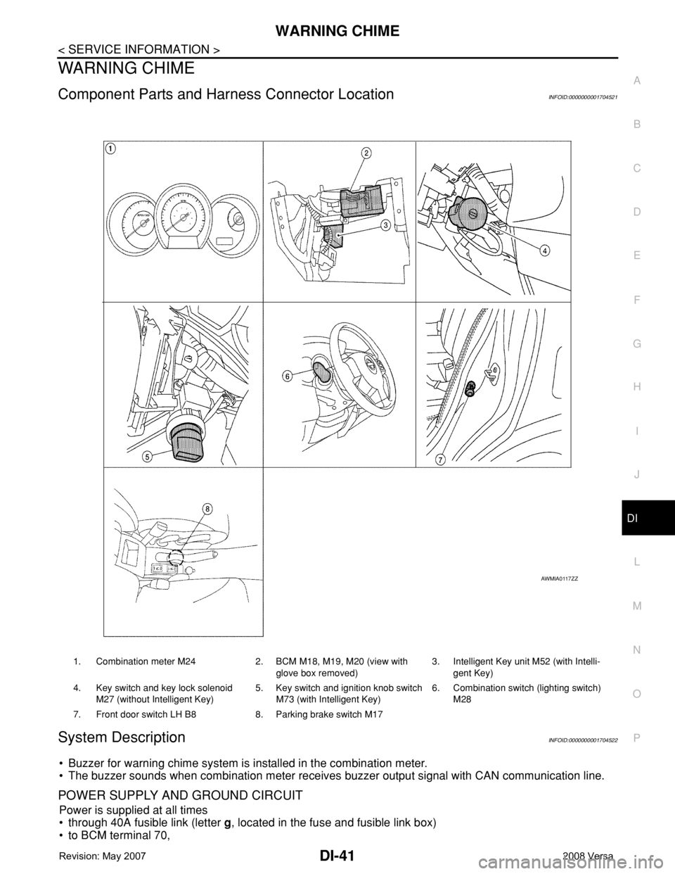
Component Parts and Harness Connector LocationINFOID:0000000001704521
System DescriptionINFOID:0000000001704522
• Buzzer for warning chime system is installed in the combination meter.
• The buzzer sounds when combination meter receives buzzer output signal with CAN communication line.
POWER SUPPLY AND GROUND CIRCUIT
Power is supplied at all times
• through 40A fusible link (letter g, located in the fuse and fusible link box)
• to BCM terminal 70,
1. Combination meter M24 2. BCM M18, M19, M20 (view with
glove box removed)3. Intelligent Key unit M52 (with Intelli-
gent Key)
4. Key switch and key lock solenoid
M27 (without Intelligent Key)5. Key switch and ignition knob switch
M73 (with Intelligent Key)6. Combination switch (lighting switch)
M28
7. Front door switch LH B8 8. Parking brake switch M17
AWMIA0117ZZ
Page 1063 of 2771
![NISSAN TIIDA 2008 Service Repair Manual DI-42
< SERVICE INFORMATION >
WARNING CHIME
• through 10A fuse [No. 8, located in the fuse block (J/B)]
• to BCM terminal 57,
• through 10A fuse [No. 13, located in the fuse block (J/B)]
• to NISSAN TIIDA 2008 Service Repair Manual DI-42
< SERVICE INFORMATION >
WARNING CHIME
• through 10A fuse [No. 8, located in the fuse block (J/B)]
• to BCM terminal 57,
• through 10A fuse [No. 13, located in the fuse block (J/B)]
• to](/manual-img/5/57399/w960_57399-1062.png)
DI-42
< SERVICE INFORMATION >
WARNING CHIME
• through 10A fuse [No. 8, located in the fuse block (J/B)]
• to BCM terminal 57,
• through 10A fuse [No. 13, located in the fuse block (J/B)]
• to combination meter terminal 27.
With ignition switch in the ON or START position, power is supplied
• through 10A fuse [No. 6, located in the fuse block (J/B)]
• to BCM terminal 38,
• through 10A fuse [No. 3, located in the fuse block (J/B)]
• to combination meter terminal 28.
Ground is supplied
• to BCM terminal 67 and
• to combination meter terminals 21, 22 and 23
• through grounds M57 and M61.
IGNITION KEY WARNING CHIME (WITHOUT INTELLIGENT KEY)
With the key inserted into the key switch, and the ignition switch in the OFF or ACC position, when driver's
door is opened, the warning chime will sound.
• BCM detects key inserted into the ignition switch, and sends key warning signal to combination meter with
CAN communication line.
• When combination meter receives key warning signal, it sounds warning chime.
IGNITION KEY WARNING CHIME (WITH INTELLIGENT KEY)
When Mechanical Key Is Used
With the key inserted into the key switch, and the ignition switch in the LOCK or ACC position, when driver's
door is opened, the warning chime will sound.
• BCM detects key inserted into the ignition switch, and sends key warning signal to combination meter with
CAN communication line.
• When combination meter receives key warning signal, it sounds warning chime.
When Intelligent Key Is Carried With The Driver
Refer to BL-76, "System Description".
LIGHT WARNING CHIME
The warning chime sounds, when driver's door is opened (door switch ON) with lighting switch ON and the
ignition switch is in any position other than ON or START.
NOTE:
BCM detected lighting switch in the 1st or 2nd position, refer to LT-62, "
Combination Switch Reading Func-
tion".
• BCM detects headlamps are illuminated, and sends light warning signal to combination meter with CAN
communication lines.
WKIA5463E
WKIA5464E
Page 1067 of 2771
![NISSAN TIIDA 2008 Service Repair Manual DI-46
< SERVICE INFORMATION >
WARNING CHIME
DATA MONITOR
Display Item List
ACTIVE TEST
Display Item List
SELF-DIAG RESULTS
Display Item List
NOTE:
If “CAN communication [U1000]” is indicated, afte NISSAN TIIDA 2008 Service Repair Manual DI-46
< SERVICE INFORMATION >
WARNING CHIME
DATA MONITOR
Display Item List
ACTIVE TEST
Display Item List
SELF-DIAG RESULTS
Display Item List
NOTE:
If “CAN communication [U1000]” is indicated, afte](/manual-img/5/57399/w960_57399-1066.png)
DI-46
< SERVICE INFORMATION >
WARNING CHIME
DATA MONITOR
Display Item List
ACTIVE TEST
Display Item List
SELF-DIAG RESULTS
Display Item List
NOTE:
If “CAN communication [U1000]” is indicated, after printing the monitor item, go to “LAN system”. Refer to
LAN-15, "
Trouble Diagnosis Flow Chart".
Trouble DiagnosisINFOID:0000000001704526
HOW TO PERFORM TROUBLE DIAGNOSIS
1. Confirm the symptom and customer complaint.
2. Understand the outline of system. Refer to DI-41, "
System Description".
3. Perform the preliminary inspection. Refer to "PRELIMINARY INSPECTION".
4. According to symptom chart, repair or replace the cause of the malfunction. Refer to "SYMPTOM
CHART".
5. Does warning chime system operate normally? If it operates normally, GO TO 6. If not, GO TO 4.
6. Inspection End.
PRELIMINARY INSPECTION
BCM diagnostic
test itemDiagnostic mode Description
Inspection by partWORK SUPPORTSupports inspections and adjustments. Commands are transmitted to the BCM for
setting the status suitable for required operation, input/output signals are received
from the BCM and received data is displayed.
DATA MONITOR Displays BCM input/output data in real time.
ACTIVE TEST Operation of electrical loads can be checked by sending drive signal to them.
SELF-DIAG RESULTS Displays BCM self-diagnosis results.
CAN DIAG SUPPORT MNTR The result of transmit/receive diagnosis of CAN communication can be read.
ECU PART NUMBER BCM part number can be read.
CONFIGURATION Performs BCM configuration read/write functions.
Monitored item ALL SIGNALSSELECTION
FROM MENUContents
IGN ON SW X X Indicates [ON/OFF] condition of ignition switch.
KEY ON SW X X Indicates [ON/OFF] condition of key switch.
DOOR SW-DR X X Indicates [ON/OFF] condition of front door switch LH.
LIGHT SW 1ST X X Indicates [ON/OFF] condition of lighting switch.
BUCKLE SW X X Indicates [ON/OFF] condition of seat belt buckle switch LH.
Test item Malfunction is detected when···
IGN KEY WARN ALM This test is able to check key warning chime operation.
LIGHT WARN ALM This test is able to check light warning chime operation.
SEAT BELT WARN TEST This test is able to check seat belt warning chime operation.
Display item [Code] Malfunction is detected when...
CAN communication [U1000] Malfunction is detected in CAN communication.
Page 1068 of 2771
WARNING CHIME
DI-47
< SERVICE INFORMATION >
C
D
E
F
G
H
I
J
L
MA
B
DI
N
O
P
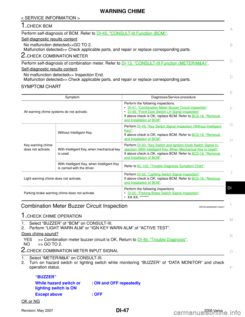
1.CHECK BCM
Perform self-diagnosis of BCM. Refer to DI-45, "
CONSULT-III Function (BCM)".
Self
-diagnostic results content
No malfunction detected>>GO TO 2.
Malfunction detected>> Check applicable parts, and repair or replace corresponding parts.
2.CHECK COMBINATION METER
Perform self-diagnosis of combination meter. Refer to DI-13, "
CONSULT-III Function (METER/M&A)".
Self
-diagnostic results content
No malfunction detected>> Inspection End.
Malfunction detected>> Check applicable parts, and repair or replace corresponding parts.
SYMPTOM CHART
Combination Meter Buzzer Circuit InspectionINFOID:0000000001704527
1.CHECK CHIME OPERATION
1. Select “BUZZER” of “BCM” on CONSULT-III.
2. Perform “LIGHT WARN ALM” or “IGN KEY WARN ALM” of “ACTIVE TEST”.
Does chime sound?
YES >> Combination meter buzzer circuit is OK. Return to DI-46, "Trouble Diagnosis".
NO >> GO TO 2.
2.CHECK COMBINATION METER INPUT SIGNAL
1. Select “METER/M&A” on CONSULT-III.
2. Turn on hazard switch or lighting switch while monitoring “BUZZER” of “DATA MONITOR” and check
operation status.
OK or NG
Symptom Diagnoses/Service procedure
All warning chime systems do not activate.Perform the following inspections.
•DI-47, "
Combination Meter Buzzer Circuit Inspection"
•DI-48, "Front Door Switch LH Signal Inspection"
If above check is OK, replace BCM. Refer to BCS-18, "Removal
and Installation of BCM".
Key warning chime
does not activate.Without Intelligent Key.Perform DI-49, "
Key Switch Signal Inspection (Without Intelligent
Key)".
If above check is OK, replace BCM. Refer to BCS-18, "
Removal
and Installation of BCM".
With Intelligent Key, when mechanical key
is used.Perform DI-50, "
Key Switch and Ignition Knob Switch Signal In-
spection (With Intelligent Key, When Mechanical Key Is Used)".
If above check is OK, replace BCM. Refer to BCS-18, "
Removal
and Installation of BCM".
With Intelligent Key, when Intelligent Key
is carried with the driver.Refer to BL-103, "
Trouble Diagnosis Symptom Chart".
Light warning chime does not activate.Perform DI-52, "
Lighting Switch Signal Inspection".
If above check is OK, replace BCM. Refer to BCS-18, "
Removal
and Installation of BCM".
Parking brake warning chime does not activatePerform the following inspections
•DI-52, "
Parking Brake Switch Signal Inspection"
• XX-XX, "*****"
“BUZZER”
While hazard switch or
lighting switch is ON : ON and OFF repeatedly
Except above : OFF
Page 1120 of 2771
EC-46
< SERVICE INFORMATION >
ON BOARD DIAGNOSTIC (OBD) SYSTEM
ON BOARD DIAGNOSTIC (OBD) SYSTEM
IntroductionINFOID:0000000001702573
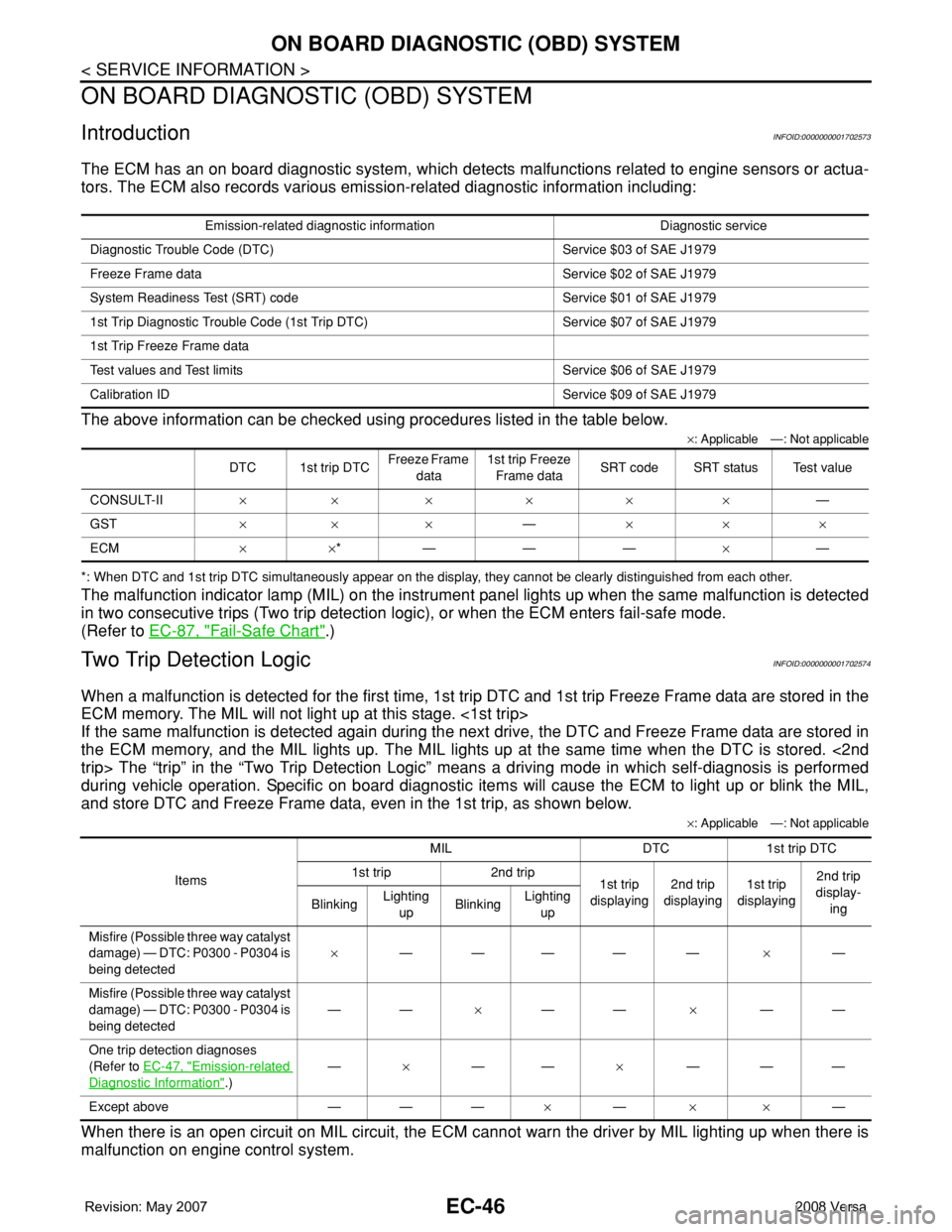
The ECM has an on board diagnostic system, which detects malfunctions related to engine sensors or actua-
tors. The ECM also records various emission-related diagnostic information including:
The above information can be checked using procedures listed in the table below.
×: Applicable —: Not applicable
*: When DTC and 1st trip DTC simultaneously appear on the display, they cannot be clearly distinguished from each other.
The malfunction indicator lamp (MIL) on the instrument panel lights up when the same malfunction is detected
in two consecutive trips (Two trip detection logic), or when the ECM enters fail-safe mode.
(Refer to EC-87, "
Fail-Safe Chart".)
Two Trip Detection LogicINFOID:0000000001702574
When a malfunction is detected for the first time, 1st trip DTC and 1st trip Freeze Frame data are stored in the
ECM memory. The MIL will not light up at this stage. <1st trip>
If the same malfunction is detected again during the next drive, the DTC and Freeze Frame data are stored in
the ECM memory, and the MIL lights up. The MIL lights up at the same time when the DTC is stored. <2nd
trip> The “trip” in the “Two Trip Detection Logic” means a driving mode in which self-diagnosis is performed
during vehicle operation. Specific on board diagnostic items will cause the ECM to light up or blink the MIL,
and store DTC and Freeze Frame data, even in the 1st trip, as shown below.
×: Applicable —: Not applicable
When there is an open circuit on MIL circuit, the ECM cannot warn the driver by MIL lighting up when there is
malfunction on engine control system.
Emission-related diagnostic information Diagnostic service
Diagnostic Trouble Code (DTC) Service $03 of SAE J1979
Freeze Frame data Service $02 of SAE J1979
System Readiness Test (SRT) code Service $01 of SAE J1979
1st Trip Diagnostic Trouble Code (1st Trip DTC) Service $07 of SAE J1979
1st Trip Freeze Frame data
Test values and Test limits Service $06 of SAE J1979
Calibration ID Service $09 of SAE J1979
DTC 1st trip DTCFreeze Frame
data1st trip Freeze
Frame dataSRT code SRT status Test value
CONSULT-II××××××—
GST×× ×—×××
ECM××*———×—
ItemsMIL DTC 1st trip DTC
1st trip 2nd trip
1st trip
displaying2nd trip
displaying1st trip
displaying2nd trip
display-
ing BlinkingLighting
upBlinkingLighting
up
Misfire (Possible three way catalyst
damage) — DTC: P0300 - P0304 is
being detected×———— —×—
Misfire (Possible three way catalyst
damage) — DTC: P0300 - P0304 is
being detected——×——×——
One trip detection diagnoses
(Refer to EC-47, "
Emission-related
Diagnostic Information".)—×——×———
Except above — — —×—××—
Page 1121 of 2771
ON BOARD DIAGNOSTIC (OBD) SYSTEM
EC-47
< SERVICE INFORMATION >
C
D
E
F
G
H
I
J
K
L
MA
EC
N
P O
Therefore, when electrical controlled throttle and part of ECM related diagnoses are continuously detected as
NG for 5 trips, ECM warns the driver that engine control system malfunctions and MIL circuit is open by means
of operating fail-safe function.
The fail-safe function also operates when above diagnoses except MIL circuit are detected, and demands the
driver to repair the malfunction.
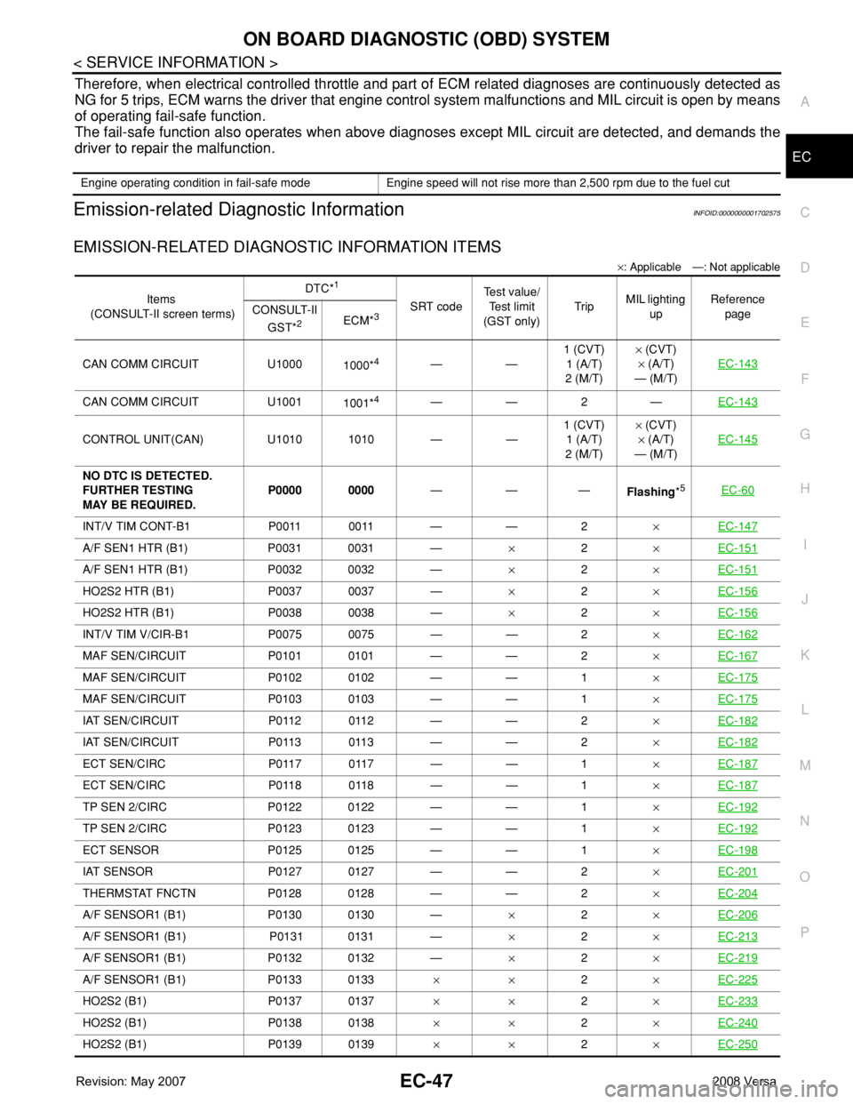
Emission-related Diagnostic InformationINFOID:0000000001702575
EMISSION-RELATED DIAGNOSTIC INFORMATION ITEMS
×: Applicable —: Not applicable
Engine operating condition in fail-safe mode Engine speed will not rise more than 2,500 rpm due to the fuel cut
Items
(CONSULT-II screen terms)DTC*
1
SRT codeTest value/
Test limit
(GST only)TripMIL lighting
upReference
page CONSULT-II
GST*
2ECM*3
CAN COMM CIRCUIT U1000
1000*4——1 (CVT)
1 (A/T)
2 (M/T)× (CVT)
× (A/T)
— (M/T)EC-143
CAN COMM CIRCUIT U1001
1001*4——2—EC-143
CONTROL UNIT(CAN) U1010 1010 — —1 (CVT)
1 (A/T)
2 (M/T)× (CVT)
× (A/T)
— (M/T)EC-145
NO DTC IS DETECTED.
FURTHER TESTING
MAY BE REQUIRED.P0000 0000———
Flashing*5EC-60
INT/V TIM CONT-B1 P0011 0011 — — 2×EC-147
A/F SEN1 HTR (B1) P0031 0031 —×2×EC-151
A/F SEN1 HTR (B1) P0032 0032 —×2×EC-151
HO2S2 HTR (B1) P0037 0037 —×2×EC-156
HO2S2 HTR (B1) P0038 0038 —×2×EC-156
INT/V TIM V/CIR-B1 P0075 0075 — — 2×EC-162
MAF SEN/CIRCUIT P0101 0101 — — 2×EC-167
MAF SEN/CIRCUIT P0102 0102 — — 1×EC-175
MAF SEN/CIRCUIT P0103 0103 — — 1×EC-175
IAT SEN/CIRCUIT P0112 0112 — — 2×EC-182
IAT SEN/CIRCUIT P0113 0113 — — 2×EC-182
ECT SEN/CIRC P0117 0117 — — 1×EC-187
ECT SEN/CIRC P0118 0118 — — 1×EC-187
TP SEN 2/CIRC P0122 0122 — — 1×EC-192
TP SEN 2/CIRC P0123 0123 — — 1×EC-192
ECT SENSOR P0125 0125 — — 1×EC-198
IAT SENSOR P0127 0127 — — 2×EC-201
THERMSTAT FNCTN P0128 0128 — — 2×EC-204
A/F SENSOR1 (B1) P0130 0130 —×2×EC-206
A/F SENSOR1 (B1) P0131 0131 —×2×EC-213
A/F SENSOR1 (B1) P0132 0132 —×2×EC-219
A/F SENSOR1 (B1) P0133 0133××2×EC-225
HO2S2 (B1) P0137 0137××2×EC-233
HO2S2 (B1) P0138 0138××2×EC-240
HO2S2 (B1) P0139 0139××2×EC-250
Page 1122 of 2771
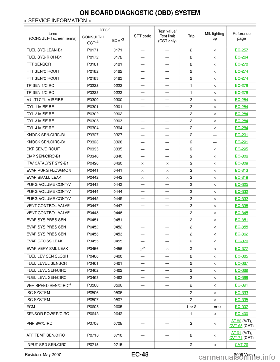
EC-48
< SERVICE INFORMATION >
ON BOARD DIAGNOSTIC (OBD) SYSTEM
FUEL SYS-LEAN-B1 P0171 0171 — — 2×EC-257
FUEL SYS-RICH-B1 P0172 0172 — — 2×EC-264
FTT SENSOR P0181 0181 — — 2×EC-270
FTT SEN/CIRCUIT P0182 0182 — — 2×EC-274
FTT SEN/CIRCUIT P0183 0183 — — 2×EC-274
TP SEN 1/CIRC P0222 0222 — — 1×EC-278
TP SEN 1/CIRC P0223 0223 — — 1×EC-278
MULTI CYL MISFIRE P0300 0300 — — 2×EC-284
CYL 1 MISFIRE P0301 0301 — — 2×EC-284
CYL 2 MISFIRE P0302 0302 — — 2×EC-284
CYL 3 MISFIRE P0303 0303 — — 2×EC-284
CYL 4 MISFIRE P0304 0304 — — 2×EC-284
KNOCK SEN/CIRC-B1 P0327 0327 — — 2 —EC-291
KNOCK SEN/CIRC-B1 P0328 0328 — — 2 —EC-291
CKP SEN/CIRCUIT P0335 0335 — — 2×EC-295
CMP SEN/CIRC-B1 P0340 0340 — — 2×EC-302
TW CATALYST SYS-B1 P0420 0420× ×2×EC-308
EVAP PURG FLOW/MON P0441 0441××2×EC-313
EVAP SMALL LEAK P0442 0442××2×EC-318
PURG VOLUME CONT/V P0443 0443 — — 2×EC-325
PURG VOLUME CONT/V P0444 0444 — — 2×EC-332
PURG VOLUME CONT/V P0445 0445 — — 2×EC-332
VENT CONTROL VALVE P0447 0447 — — 2×EC-338
VENT CONTROL VALVE P0448 0448 — — 2×EC-345
EVAP SYS PRES SEN P0451 0451 — — 2×EC-351
EVAP SYS PRES SEN P0452 0452 — — 2×EC-355
EVAP SYS PRES SEN P0453 0453 — — 2×EC-362
EVAP GROSS LEAK P0455 0455 — — 2×EC-370
EVAP VERY SML LEAK P0456 0456
×*6×2×EC-377
FUEL LEV SEN SLOSH P0460 0460 — — 2×EC-385
FUEL LEVEL SENSOR P0461 0461 — — 2×EC-387
FUEL LEVL SEN/CIRC P0462 0462 — — 2×EC-389
FUEL LEVL SEN/CIRC P0463 0463 — — 2×EC-389
VEH SPEED SEN/CIRC*7P0500 0500 — — 2×EC-391
ISC SYSTEM P0506 0506 — — 2×EC-393
ISC SYSTEM P0507 0507 — — 2×EC-395
ECM P0605 0605 — — 1 or 2 — or ×EC-397
SENSOR POWER/CIRC P0643 0643 — — 1×EC-400
PNP SW/CIRC P0705 0705 — — 2×AT- 8 6 (A/T),
CVT-65
(CVT)
ATF TEMP SEN/CIRC P0710 0710 — — 2×AT- 9 1
(A/T),
CVT-71
(CVT)
INPUT SPD SEN/CIRC P0715 0715 — — 2×CVT-76
Items
(CONSULT-II screen terms)DTC*
1
SRT codeTest value/
Test limit
(GST only)TripMIL lighting
upReference
page CONSULT-II
GST*
2ECM*3