2008 NISSAN TIIDA Lighting System
[x] Cancel search: Lighting SystemPage 2173 of 2771
LT-36
< SERVICE INFORMATION >
HEADLAMP (FOR CANADA) - DAYTIME LIGHT SYSTEM -
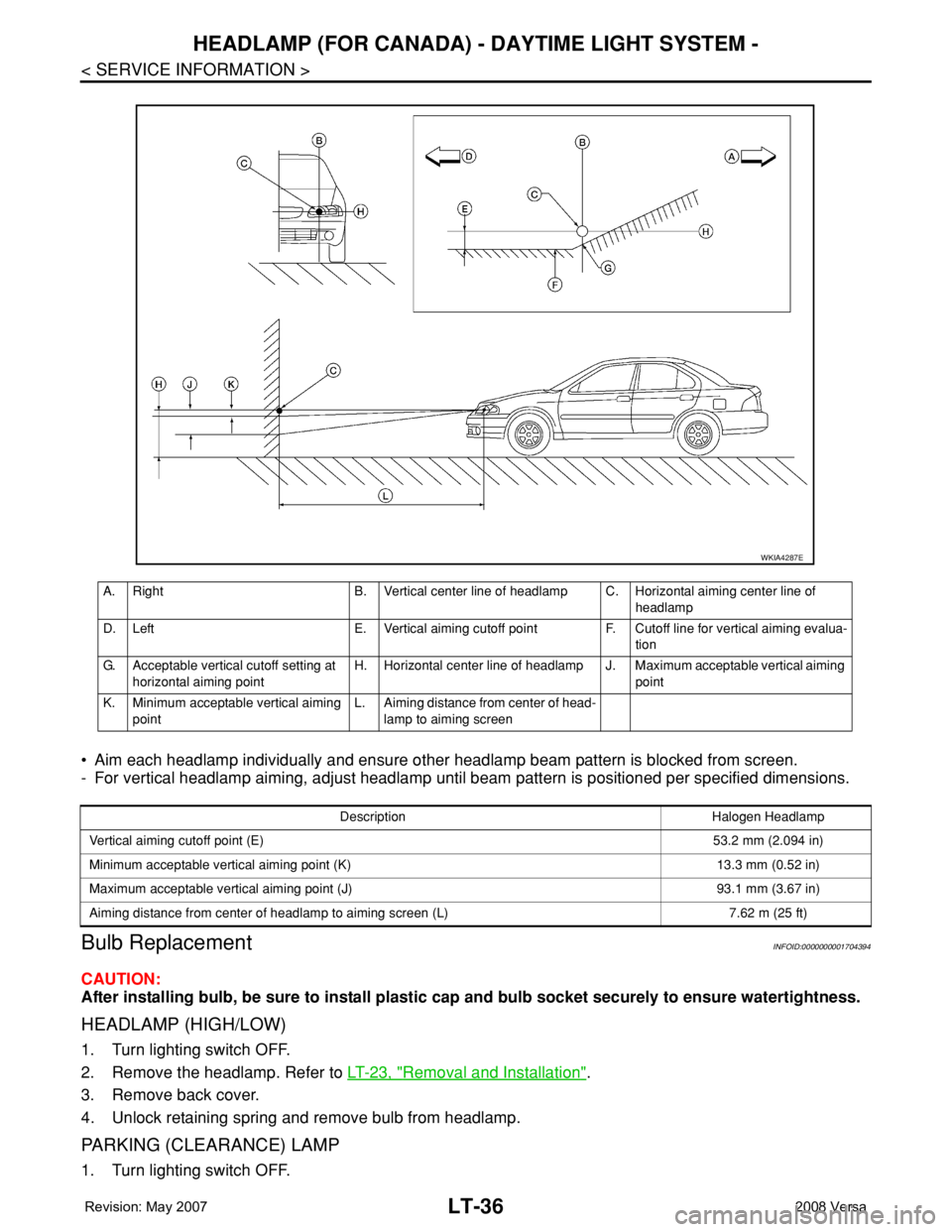
• Aim each headlamp individually and ensure other headlamp beam pattern is blocked from screen.
- For vertical headlamp aiming, adjust headlamp until beam pattern is positioned per specified dimensions.
Bulb ReplacementINFOID:0000000001704394
CAUTION:
After installing bulb, be sure to install plastic cap and bulb socket securely to ensure watertightness.
HEADLAMP (HIGH/LOW)
1. Turn lighting switch OFF.
2. Remove the headlamp. Refer to LT-23, "
Removal and Installation".
3. Remove back cover.
4. Unlock retaining spring and remove bulb from headlamp.
PARKING (CLEARANCE) LAMP
1. Turn lighting switch OFF.
A. Right B. Vertical center line of headlamp C. Horizontal aiming center line of
headlamp
D. Left E. Vertical aiming cutoff point F. Cutoff line for vertical aiming evalua-
tion
G. Acceptable vertical cutoff setting at
horizontal aiming pointH. Horizontal center line of headlamp J. Maximum acceptable vertical aiming
point
K. Minimum acceptable vertical aiming
pointL. Aiming distance from center of head-
lamp to aiming screen
WKIA4287E
Description Halogen Headlamp
Vertical aiming cutoff point (E)53.2 mm (2.094 in)
Minimum acceptable vertical aiming point (K) 13.3 mm (0.52 in)
Maximum acceptable vertical aiming point (J) 93.1 mm (3.67 in)
Aiming distance from center of headlamp to aiming screen (L) 7.62 m (25 ft)
Page 2174 of 2771
HEADLAMP (FOR CANADA) - DAYTIME LIGHT SYSTEM -
LT-37
< SERVICE INFORMATION >
C
D
E
F
G
H
I
J
L
MA
B
LT
N
O
P
2. Remove the headlamp. Refer to LT-23, "Removal and Installation".
3. Turn bulb socket counterclockwise and unlock it.
4. Remove bulb from its socket.
FRONT TURN SIGNAL LAMP
1. Turn lighting switch OFF.
2. Remove the headlamp. Refer to LT-23, "
Removal and Installation".
3. Turn bulb socket counterclockwise and unlock it.
4. Remove bulb from its socket.
Removal and InstallationINFOID:0000000001704395
REMOVAL
1. Disconnect the negative battery terminal.
2. Remove front bumper fascia. Refer to EI-14
.
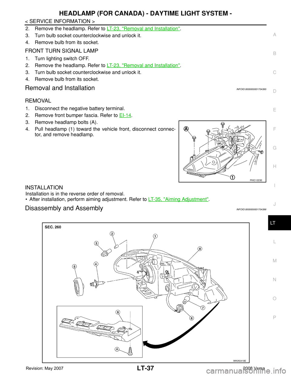
3. Remove headlamp bolts (A).
4. Pull headlamp (1) toward the vehicle front, disconnect connec-
tor, and remove headlamp.
INSTALLATION
Installation is in the reverse order of removal.
• After installation, perform aiming adjustment. Refer to LT-35, "
Aiming Adjustment".
Disassembly and AssemblyINFOID:0000000001704396
PKIC1223E
WKIA5418E
Page 2176 of 2771
FRONT FOG LAMP
LT-39
< SERVICE INFORMATION >
C
D
E
F
G
H
I
J
L
MA
B
LT
N
O
P
FRONT FOG LAMP
Component Parts and Harness Connector LocationINFOID:0000000001704397
System DescriptionINFOID:0000000001704398
The front fog lamps are controlled by lighting switch inputs to the BCM (body control module). The lighting
switch must be in the 1ST or 2ND position with the high beams OFF before the BCM will request the IPDM E/
R (intelligent power distribution module engine room) to turn the front fog lamps on. The BCM requests the
front fog lamps over the CAN communication lines to the IPDM E/R. The CPU (central processing unit) of the
IPDM E/R controls the front fog lamp relay coil ground. When energized, the relay directs power to the front
fog lamps.
OUTLINE
Power is supplied at all times:
• to front fog lamp relay (located in IPDM E/R),
• to ignition relay (located in IPDM E/R),
• through 15A fuse (No. 52, located in IPDM E/R) and
• through 20A fuse (No. 53, located in IPDM E/R)
• to CPU located in IPDM E/R,
• through 40A fusible link (letter g , located in the fuse and fusible link box)
• to BCM terminal 70,
• through 10A fuse [No. 8, located in fuse block (J/B)]
• to BCM terminal 57,
• through 10A fuse [No. 13, located in fuse block (J/B)]
• to combination meter terminal 27.
With the ignition switch in the ON or START position, power is supplied:
• to ignition relay (located in IPDM E/R),
• through 10A fuse [No. 6, located in fuse block (J/B)]
• to BCM terminal 38.
With the ignition switch in the ACC or ON position, power is supplied
• through 10A fuse [No. 20, located in fuse block (J/B)]
• to BCM terminal 11.
Ground is supplied
• to BCM terminal 67
• through grounds M57 and M61,
• to IPDM E/R terminals 39 and 59
• through grounds E15 and E24.
FOG LAMP OPERATION
The front fog lamp switch is built into the lighting switch. The lighting switch must be in 1ST position or 2ND
position and front fog lamp switch must be ON position for front fog lamp operation. The fog lamp will not oper-
ate with the high beam headlamps ON.
When the front fog lamp switch is in the ON position, the BCM sends a request, via the CAN communication
lines, to the CPU of the IPDM E/R to ground the coil side of the front fog lamp relay. The front fog lamp relay
then directs power
• through 15A fuse (No. 56, located in IPDM E/R)
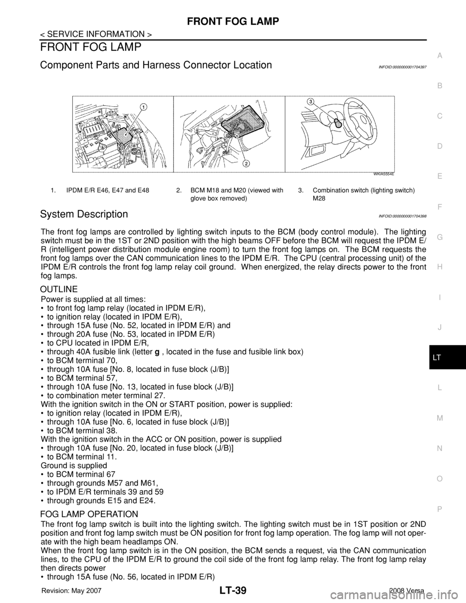
1. IPDM E/R E46, E47 and E48 2. BCM M18 and M20 (viewed with
glove box removed)3. Combination switch (lighting switch)
M28
WKIA5554E
Page 2180 of 2771
FRONT FOG LAMP
LT-43
< SERVICE INFORMATION >
C
D
E
F
G
H
I
J
L
MA
B
LT
N
O
P
How to Proceed with Trouble DiagnosisINFOID:0000000001704403
1. Confirm the symptom or customer complaint.
2. Understand operation description and function description. Refer to LT-39, "
System Description" .
3. Perform the Preliminary Check. Refer to LT-43, "
Preliminary Check" .
4. Check symptom and repair or replace the cause of the malfunction.
5. Do the front fog lamps operate normally? If YES, GO TO 6. If NO, GO TO 4.
6. INSPECTION END.
Preliminary CheckINFOID:0000000001704404
CHECK POWER SUPPLY AND GROUND CIRCUIT FOR BCM
Refer to BCS-15, "BCM Power Supply and Ground Circuit Inspection" .
CHECK POWER SUPPLY AND GROUND CIRCUIT FOR IPDM E/R
Refer to PG-25, "IPDM E/R Power/Ground Circuit Inspection" .
CONSULT-III Function (BCM)INFOID:0000000001704405
Refer to BCS-16, "CONSULT-III Function (BCM)" .
CONSULT-III Function (IPDM E/R)INFOID:0000000001704406
Refer to PG-17, "CONSULT-III Function (IPDM E/R)" .
Front Fog lamps Do Not Illuminate (Both Sides)INFOID:0000000001704407
1.INSPECT FOG LAMP FUSE
Inspect fog lamp 15A fuse No. 56 in IPDM E/R.
OK or NG
OK >> GO TO 2.
NG >> Repair harness.
2.CHECK COMBINATION SWITCH INPUT SIGNAL
1. Select “BCM” on CONSULT-III. Select “HEAD LAMP” on “SELECT TEST ITEM” screen.
2. Select “DATA MONITOR” on “SELECT DIAG MODE” screen. Make sure that “FR FOG SW” turns ON-
OFF linked with operation of fog lamp switch.
With CONSULT-III
Select “BCM” on CONSULT-III. With “HEAD LAMP” data monitor, make sure “FR FOG SW” turns ON-OFF
linked with operation of front fog lamp switch.
Without CONSULT-III
Refer to LT-63, "
Combination Switch Inspection" .
OK or NG
OK >> GO TO 3.
NG >> Check combination switch (lighting switch). Refer to LT-63, "
Combination Switch Inspection" .
3.FOG LAMP ACTIVE TEST
With CONSULT-III
1. Select “IPDM E/R” on CONSULT-III. Select “ACTIVE TEST” on “SELECT DIAG MODE” screen.
2. Select “EXTERNAL LAMPS” on “SELECT TEST ITEM” screen.
3. Touch “FOG” screen.
4. Make sure front fog lamp operates.
Without CONSULT-IIIWhen fog lamp switch is ON : FR FOG SW ON
Front fog lamp should operate.
Page 2185 of 2771
LT-48
< SERVICE INFORMATION >
TURN SIGNAL AND HAZARD WARNING LAMPS
TURN SIGNAL AND HAZARD WARNING LAMPS
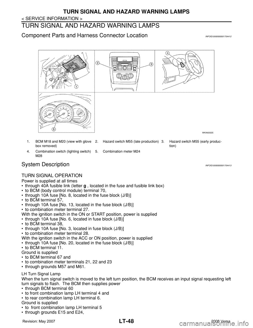
Component Parts and Harness Connector LocationINFOID:0000000001704412
System DescriptionINFOID:0000000001704413
TURN SIGNAL OPERATION
Power is supplied at all times
• through 40A fusible link (letter g , located in the fuse and fusible link box)
• to BCM (body control module) terminal 70,
• through 10A fuse [No. 8, located in the fuse block (J/B)]
• to BCM terminal 57,
• through 10A fuse [No. 13, located in the fuse block (J/B)]
• to combination meter terminal 27.
With the ignition switch in the ON or START position, power is supplied
• through 10A fuse [No. 6, located in fuse block (J/B)]
• to BCM terminal 38,
• through 10A fuse [No. 3, located in fuse block (J/B)]
• to combination meter terminal 28.
With the ignition switch in the ACC or ON position, power is supplied
• through 10A fuse [No. 20, located in the fuse block (J/B)]
• to BCM terminal 11.
Ground is supplied
• to BCM terminal 67 and
• to combination meter terminals 21, 22 and 23
• through grounds M57 and M61.
LH Turn Signal Lamp
When the turn signal switch is moved to the left turn position, the BCM receives an input signal requesting left
turn signals to flash. The BCM then supplies power
• through BCM terminal 60
• to front combination lamp LH terminal 4 and
• to rear combination lamp LH terminal 6.
Ground is supplied
• to front combination lamp LH terminal 5
• through grounds E15 and E24,
1. BCM M18 and M20 (view with glove
box removed)2. Hazard switch M55 (late production) 3. Hazard switch M55 (early produc-
tion)
4. Combination switch (lighting switch)
M285. Combination meter M24
WKIA6002E
Page 2200 of 2771
COMBINATION SWITCH
LT-63
< SERVICE INFORMATION >
C
D
E
F
G
H
I
J
L
MA
B
LT
N
O
P
Terminal and Reference Value for BCMINFOID:0000000001704434
Refer to BCS-11, "Terminal and Reference Value for BCM" .
CONSULT-III Function (BCM)INFOID:0000000001704435
Refer to LT- 11 , "CONSULT-III Function (BCM)" .
Combination Switch InspectionINFOID:0000000001704436
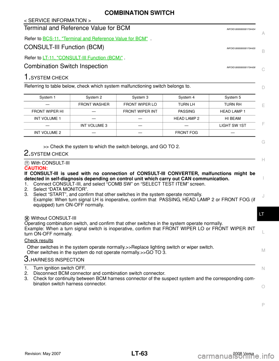
1.SYSTEM CHECK
Referring to table below, check which system malfunctioning switch belongs to.
>> Check the system to which the switch belongs, and GO TO 2.
2.SYSTEM CHECK
With CONSULT-III
CAUTION:
If CONSULT-III is used with no connection of CONSULT-III CONVERTER, malfunctions might be
detected in self-diagnosis depending on control unit which carry out CAN communication.
1. Connect CONSULT-III, and select “COMB SW” on “SELECT TEST ITEM” screen.
2. Select “DATA MONITOR”.
3. Select “START”, and confirm that other switches in the system operate normally.
Example: When turn signal LH is inoperative, confirm that PASSING, HEAD LAMP 2 or FRONT FOG (if
equipped) turn ON-OFF normally.
Without CONSULT-III
Operating combination switch, and confirm that other switches in the system operate normally.
Example: When a turn signal switch is inoperative, confirm that FRONT WIPER LO or FRONT WIPER INT
turn ON-OFF normally.
Check results
Other switches in the system operate normally.>>Replace lighting switch or wiper switch.
Other switches in the system do not operate normally.>>GO TO 3.
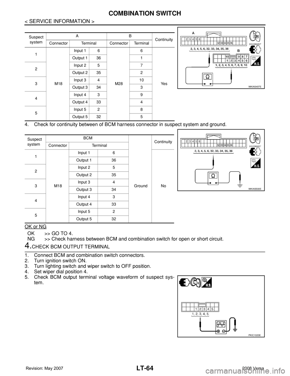
3.HARNESS INSPECTION
1. Turn ignition switch OFF.
2. Disconnect BCM connector and combination switch connector.
3. Check for continuity between BCM harness connector of the suspect system and the corresponding com-
bination switch harness connector.
System 1 System 2 System 3 System 4 System 5
— FRONT WASHER FRONT WIPER LO TURN LH TURN RH
FRONT WIPER HI — FRONT WIPER INT PASSING HEAD LAMP 1
INT VOLUME 1 — — HEAD LAMP 2 HI BEAM
— INT VOLUME 3 — — LIGHT SW 1ST
INT VOLUME 2 — — FRONT FOG —
Page 2201 of 2771
LT-64
< SERVICE INFORMATION >
COMBINATION SWITCH
4. Check for continuity between of BCM harness connector in suspect system and ground.
OK or NG
OK >> GO TO 4.
NG >> Check harness between BCM and combination switch for open or short circuit.
4.CHECK BCM OUTPUT TERMINAL
1. Connect BCM and combination switch connectors.
2. Turn ignition switch ON.
3. Turn lighting switch and wiper switch to OFF position.
4. Set wiper dial position 4.
5. Check BCM output terminal voltage waveform of suspect sys-
tem.
Suspect
systemAB
Continuity
Connector Terminal Connector Terminal
1
M18Input 1 6
M286
Ye s Output 1 36 1
2Input 2 5 7
Output 2 35 2
3Input 3 4 10
Output 3 34 3
4Input 4 3 9
Output 4 33 4
5Input 5 2 8
Output 5 32 5
Suspect
systemBCM
Continuity
Connector Terminal
1
M18Input 1 6
Ground No Output 1 36
2Input 2 5
Output 2 35
3Input 3 4
Output 3 34
4Input 4 3
Output 4 33
5Input 5 2
Output 5 32
WKIA5497E
WKIA5500E
PKIC1020E
Page 2202 of 2771
COMBINATION SWITCH
LT-65
< SERVICE INFORMATION >
C
D
E
F
G
H
I
J
L
MA
B
LT
N
O
P
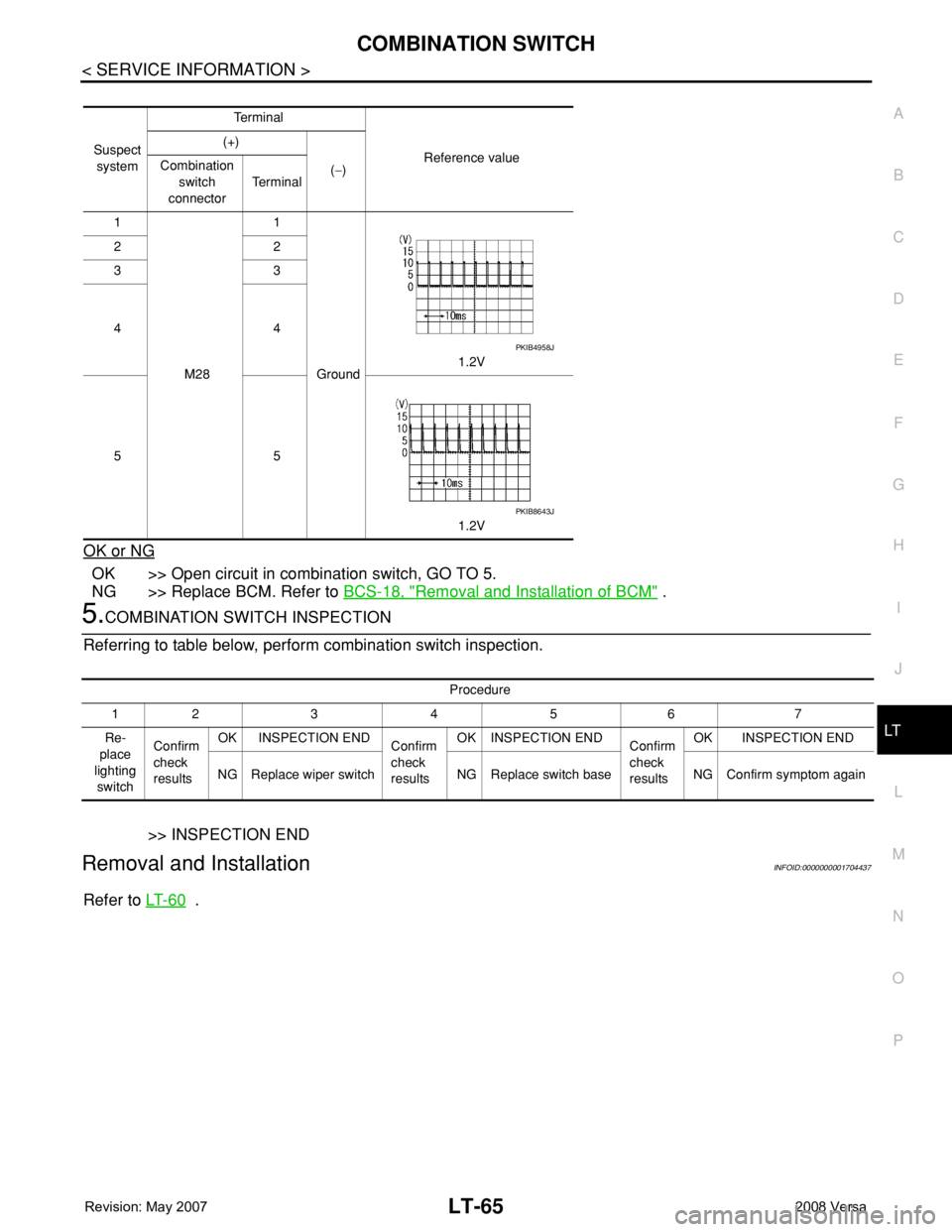
OK or NG
OK >> Open circuit in combination switch, GO TO 5.
NG >> Replace BCM. Refer to BCS-18, "
Removal and Installation of BCM" .
5.COMBINATION SWITCH INSPECTION
Referring to table below, perform combination switch inspection.
>> INSPECTION END
Removal and InstallationINFOID:0000000001704437
Refer to LT- 6 0 .
Suspect
systemTe r m i n a l
Reference value (+)
(−) Combination
switch
connectorTe r m i n a l
1
M281
Ground1.2V 22
33
44
55
1.2V
PKIB4958J
PKIB8643J
Procedure
12 3 4 5 6 7
Re-
place
lighting
switchConfirm
check
resultsOK INSPECTION END
Confirm
check
resultsOK INSPECTION END
Confirm
check
resultsOK INSPECTION END
NG Replace wiper switch NG Replace switch base NG Confirm symptom again