2008 NISSAN TIIDA meter
[x] Cancel search: meterPage 6 of 2771

2008
QUICK REFERENCE CHART: VERSA
*: Fuel, engine coolant and engine oil full. Spare tire, jack, hand tools and mats in designated positions.
General SpecificationINFOID:0000000001903532
Brake PedalINFOID:0000000001903533
Unit: mm (in)
Front Disc BrakeINFOID:0000000001903534
Unit: mm (in)
Rear Drum BrakeINFOID:0000000001903535
Unit: mm (in)
Front brake Brake model CLZ25VACylinder bore diameter 57.2 mm (2.252 in)
Pad
Length × width × thickness 125.6 mm
× 46.0 mm × 9.5 mm
(4.945 in × 1.811 in × 0.374 in)
Rotor outer diameter × thickness 280 mm × 24.0 mm (11.02 in × 0.945 in)
Rear brake Brake model LT20D Cylinder bore diameter 15.87 mm (0.625 in)
Lining
Length × width × thickness 194.1 mm
× 30.0 mm × 4.0 mm
(7.642 in × 1.181 in × 0.157 in)
Drum outer diameter 228.6 mm (9.000 in)
Master cylinder Cylinder bore diameter 22.22 mm (0.875 in)
Control valve Valve model Electric brake force distribution
Brake booster Booster model C255 Diaphragm diameter 255 mm (10.04 in)
Brake pedal free height (from dash panel top surface) A/T, CVT model 172.4 - 182.4 (6.79 - 7.18)
M/T model 162.3 - 172.3 (6.39 - 6.78)
Brake pedal depressed height
[under a force of 490 N (50 kg-f, 110 lb-f) with the engine running] A/T, CVT model 98 (3.86) or more
M/T model 90 (3.54) or more
Clearance between brake pedal lever and the threaded end of stop lamp switch 0.74 - 1.96 (0.0291 - 0.0772)
Pedal play 3 - 11 (0.12 - 0.43)
Brake modelCLZ25VA
Brake pad Standard thickness (new) 9.5 (0.374)
Repair limit thickness 2.0 (0.079)
Disc rotor Standard thickness (new) 24.0 (0.945)
Repair limit thickness 22.0 (0.866)
Runout limit 0.04 (0.0016)
Maximum uneven wear (mea-
sured at 8 positions)
0.02 mm (0.0008 in) or less
Brake model
LT 2 0 D
Brake lining Standard thickness (new) 4.0 (0.157)
Repair limit thickness 1.5 (0.059)
Drum Standard inner diameter (new) 228.6 (9.000)
Repair limit inner diameter 230.0 (9.055)
Page 49 of 2771
ON BOARD DIAGNOSTIC (OBD) SYSTEM
AT-37
< SERVICE INFORMATION >
D
E
F
G
H
I
J
K
L
MA
B
AT
N
O
P
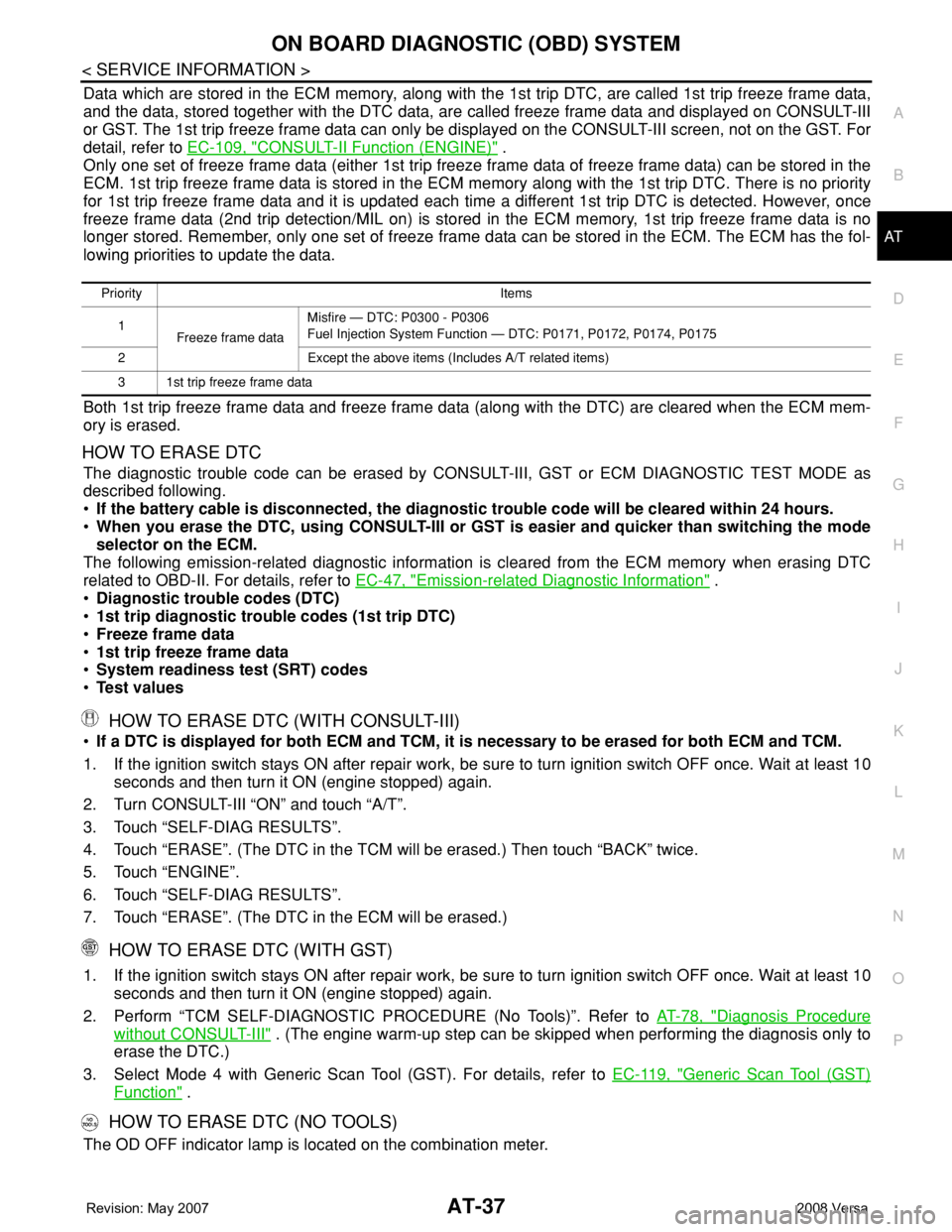
Data which are stored in the ECM memory, along with the 1st trip DTC, are called 1st trip freeze frame data,
and the data, stored together with the DTC data, are called freeze frame data and displayed on CONSULT-III
or GST. The 1st trip freeze frame data can only be displayed on the CONSULT-III screen, not on the GST. For
detail, refer to EC-109, "
CONSULT-II Function (ENGINE)" .
Only one set of freeze frame data (either 1st trip freeze frame data of freeze frame data) can be stored in the
ECM. 1st trip freeze frame data is stored in the ECM memory along with the 1st trip DTC. There is no priority
for 1st trip freeze frame data and it is updated each time a different 1st trip DTC is detected. However, once
freeze frame data (2nd trip detection/MIL on) is stored in the ECM memory, 1st trip freeze frame data is no
longer stored. Remember, only one set of freeze frame data can be stored in the ECM. The ECM has the fol-
lowing priorities to update the data.
Both 1st trip freeze frame data and freeze frame data (along with the DTC) are cleared when the ECM mem-
ory is erased.
HOW TO ERASE DTC
The diagnostic trouble code can be erased by CONSULT-III, GST or ECM DIAGNOSTIC TEST MODE as
described following.
•If the battery cable is disconnected, the diagnostic trouble code will be cleared within 24 hours.
•When you erase the DTC, using CONSULT-III or GST is easier and quicker than switching the mode
selector on the ECM.
The following emission-related diagnostic information is cleared from the ECM memory when erasing DTC
related to OBD-II. For details, refer to EC-47, "
Emission-related Diagnostic Information" .
•Diagnostic trouble codes (DTC)
•1st trip diagnostic trouble codes (1st trip DTC)
•Freeze frame data
•1st trip freeze frame data
•System readiness test (SRT) codes
•Test values
HOW TO ERASE DTC (WITH CONSULT-III)
•If a DTC is displayed for both ECM and TCM, it is necessary to be erased for both ECM and TCM.
1. If the ignition switch stays ON after repair work, be sure to turn ignition switch OFF once. Wait at least 10
seconds and then turn it ON (engine stopped) again.
2. Turn CONSULT-III “ON” and touch “A/T”.
3. Touch “SELF-DIAG RESULTS”.
4. Touch “ERASE”. (The DTC in the TCM will be erased.) Then touch “BACK” twice.
5. Touch “ENGINE”.
6. Touch “SELF-DIAG RESULTS”.
7. Touch “ERASE”. (The DTC in the ECM will be erased.)
HOW TO ERASE DTC (WITH GST)
1. If the ignition switch stays ON after repair work, be sure to turn ignition switch OFF once. Wait at least 10
seconds and then turn it ON (engine stopped) again.
2. Perform “TCM SELF-DIAGNOSTIC PROCEDURE (No Tools)”. Refer to AT-78, "
Diagnosis Procedure
without CONSULT-III" . (The engine warm-up step can be skipped when performing the diagnosis only to
erase the DTC.)
3. Select Mode 4 with Generic Scan Tool (GST). For details, refer to EC-119, "
Generic Scan Tool (GST)
Function" .
HOW TO ERASE DTC (NO TOOLS)
The OD OFF indicator lamp is located on the combination meter.
Priority Items
1
Freeze frame dataMisfire — DTC: P0300 - P0306
Fuel Injection System Function — DTC: P0171, P0172, P0174, P0175
2 Except the above items (Includes A/T related items)
3 1st trip freeze frame data
Page 51 of 2771
TROUBLE DIAGNOSIS
AT-39
< SERVICE INFORMATION >
D
E
F
G
H
I
J
K
L
MA
B
AT
N
O
P
TROUBLE DIAGNOSIS
DTC Inspection Priority ChartINFOID:0000000001703177
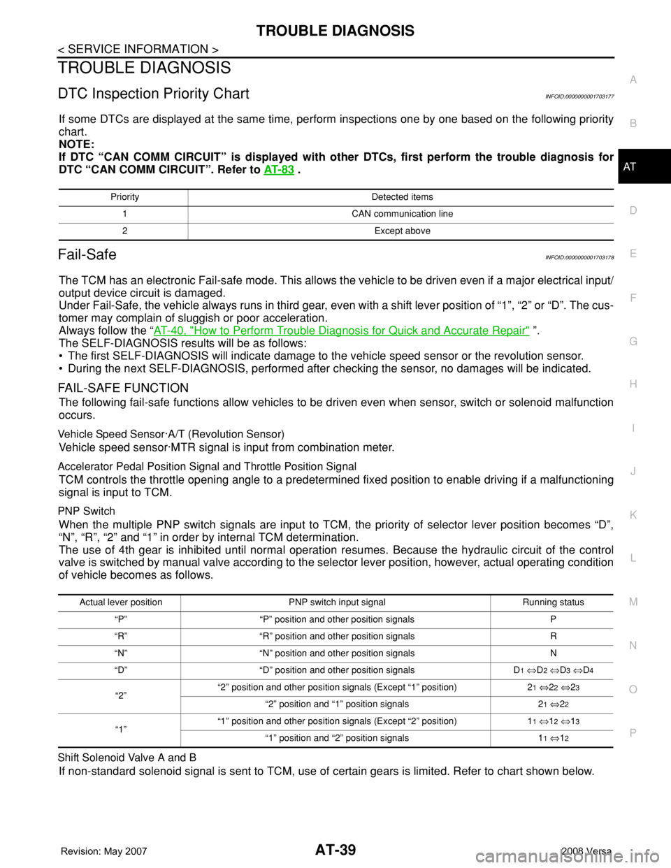
If some DTCs are displayed at the same time, perform inspections one by one based on the following priority
chart.
NOTE:
If DTC “CAN COMM CIRCUIT” is displayed with other DTCs, first perform the trouble diagnosis for
DTC “CAN COMM CIRCUIT”. Refer to AT- 8 3
.
Fail-SafeINFOID:0000000001703178
The TCM has an electronic Fail-safe mode. This allows the vehicle to be driven even if a major electrical input/
output device circuit is damaged.
Under Fail-Safe, the vehicle always runs in third gear, even with a shift lever position of “1”, “2” or “D”. The cus-
tomer may complain of sluggish or poor acceleration.
Always follow the “AT-40, "
How to Perform Trouble Diagnosis for Quick and Accurate Repair" ”.
The SELF-DIAGNOSIS results will be as follows:
• The first SELF-DIAGNOSIS will indicate damage to the vehicle speed sensor or the revolution sensor.
• During the next SELF-DIAGNOSIS, performed after checking the sensor, no damages will be indicated.
FAIL-SAFE FUNCTION
The following fail-safe functions allow vehicles to be driven even when sensor, switch or solenoid malfunction
occurs.
Vehicle Speed Sensor·A/T (Revolution Sensor)
Vehicle speed sensor·MTR signal is input from combination meter.
Accelerator Pedal Position Signal and Throttle Position Signal
TCM controls the throttle opening angle to a predetermined fixed position to enable driving if a malfunctioning
signal is input to TCM.
PNP Switch
When the multiple PNP switch signals are input to TCM, the priority of selector lever position becomes “D”,
“N”, “R”, “2” and “1” in order by internal TCM determination.
The use of 4th gear is inhibited until normal operation resumes. Because the hydraulic circuit of the control
valve is switched by manual valve according to the selector lever position, however, actual operating condition
of vehicle becomes as follows.
Shift Solenoid Valve A and B
If non-standard solenoid signal is sent to TCM, use of certain gears is limited. Refer to chart shown below.
Priority Detected items
1 CAN communication line
2 Except above
Actual lever position PNP switch input signal Running status
“P” “P” position and other position signals P
“R” “R” position and other position signals R
“N” “N” position and other position signals N
“D” “D” position and other position signals D
1 ⇔D2 ⇔D3 ⇔D4
“2”“2” position and other position signals (Except “1” position) 21 ⇔22 ⇔23
“2” position and “1” position signals 21 ⇔22
“1”“1” position and other position signals (Except “2” position) 11 ⇔12 ⇔13
“1” position and “2” position signals 11 ⇔12
Page 60 of 2771
AT-48
< SERVICE INFORMATION >
TROUBLE DIAGNOSIS
Inspections Before Trouble Diagnosis
INFOID:0000000001703182
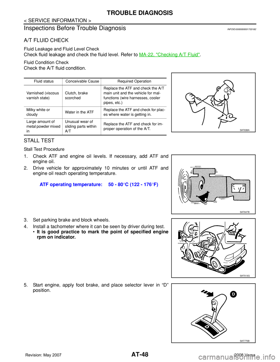
A/T FLUID CHECK
Fluid Leakage and Fluid Level Check
Check fluid leakage and check the fluid level. Refer to MA-22, "Checking A/T Fluid".
Fluid Condition Check
Check the A/T fluid condition.
STALL TEST
Stall Test Procedure
1. Check ATF and engine oil levels. If necessary, add ATF and
engine oil.
2. Drive vehicle for approximately 10 minutes or until ATF and
engine oil reach operating temperature.
3. Set parking brake and block wheels.
4. Install a tachometer where it can be seen by driver during test.
•It is good practice to mark the point of specified engine
rpm on indicator.
5. Start engine, apply foot brake, and place selector lever in “D”
position.
Fluid status Conceivable Cause Required Operation
Varnished (viscous
varnish state)Clutch, brake
scorchedReplace the ATF and check the A/T
main unit and the vehicle for mal-
functions (wire harnesses, cooler
pipes, etc.)
Milky white or
cloudyWater in the ATFReplace the ATF and check for plac-
es where water is getting in.
Large amount of
metal powder mixed
inUnusual wear of
sliding parts within
A/TReplace the ATF and check for im-
proper operation of the A/T.
SAT638A
ATF operating temperature: 50 - 80°C (122 - 176°F)
SAT647B
SAT513G
SAT775B
Page 85 of 2771
TROUBLE DIAGNOSIS
AT-73
< SERVICE INFORMATION >
D
E
F
G
H
I
J
K
L
MA
B
AT
N
O
P
*1: These terminals are connected to the data link connector.
*2: These terminals are connected to the ECM.
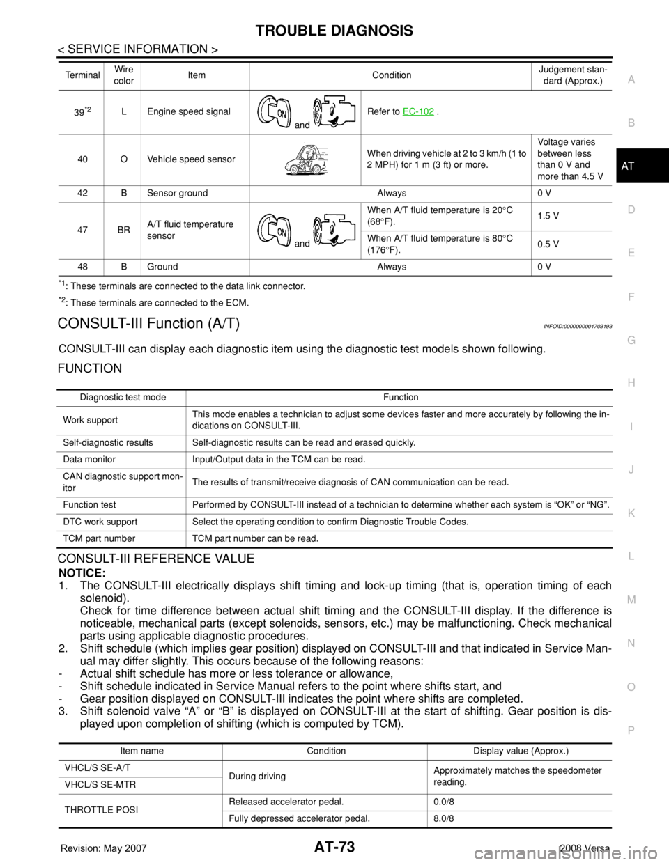
CONSULT-III Function (A/T)INFOID:0000000001703193
CONSULT-III can display each diagnostic item using the diagnostic test models shown following.
FUNCTION
CONSULT-III REFERENCE VALUE
NOTICE:
1. The CONSULT-III electrically displays shift timing and lock-up timing (that is, operation timing of each
solenoid).
Check for time difference between actual shift timing and the CONSULT-III display. If the difference is
noticeable, mechanical parts (except solenoids, sensors, etc.) may be malfunctioning. Check mechanical
parts using applicable diagnostic procedures.
2. Shift schedule (which implies gear position) displayed on CONSULT-III and that indicated in Service Man-
ual may differ slightly. This occurs because of the following reasons:
- Actual shift schedule has more or less tolerance or allowance,
- Shift schedule indicated in Service Manual refers to the point where shifts start, and
- Gear position displayed on CONSULT-III indicates the point where shifts are completed.
3. Shift solenoid valve “A” or “B” is displayed on CONSULT-III at the start of shifting. Gear position is dis-
played upon completion of shifting (which is computed by TCM).
39*2L Engine speed signal
and Refer to EC-102 .
40 O Vehicle speed sensorWhen driving vehicle at 2 to 3 km/h (1 to
2 MPH) for 1 m (3 ft) or more.Voltage varies
between less
than 0 V and
more than 4.5 V
42 B Sensor ground Always 0 V
47 BRA/T fluid temperature
sensor
and When A/T fluid temperature is 20°C
(68°F).1.5 V
When A/T fluid temperature is 80°C
(176°F).0.5 V
48 B Ground Always 0 V Te r m i n a lWire
colorItem ConditionJudgement stan-
dard (Approx.)
Diagnostic test mode Function
Work supportThis mode enables a technician to adjust some devices faster and more accurately by following the in-
dications on CONSULT-III.
Self-diagnostic results Self-diagnostic results can be read and erased quickly.
Data monitor Input/Output data in the TCM can be read.
CAN diagnostic support mon-
itorThe results of transmit/receive diagnosis of CAN communication can be read.
Function test Performed by CONSULT-III instead of a technician to determine whether each system is “OK” or “NG”.
DTC work support Select the operating condition to confirm Diagnostic Trouble Codes.
TCM part number TCM part number can be read.
Item name Condition Display value (Approx.)
VHCL/S SE-A/T
During drivingApproximately matches the speedometer
reading.
VHCL/S SE-MTR
THROTTLE POSIReleased accelerator pedal. 0.0/8
Fully depressed accelerator pedal. 8.0/8
Page 86 of 2771

AT-74
< SERVICE INFORMATION >
TROUBLE DIAGNOSIS
FLUID TEMP SE When A/T fluid temperature is 20°C (68°F). 1.5 V
When A/T fluid temperature is 80°C (176°F). 0.5 V
BATTERY VOLT When turning ignition switch to “ON”. Battery voltage
ENGINE SPEED Engine runningApproximately matches the tachometer
reading.
TURBINE REV During driving (lock-up ON) Approximately matches the engine speed.
OVERDRIVE SWWhen overdrive control switch is depressed. ON
When overdrive control switch is released. OFF
PN POSI SWWhen setting selector lever to “N” or “P” position. ON
When setting selector lever to other positions. OFF
R POSITION SWWhen setting selector lever to “R” position. ON
When setting selector lever to other positions. OFF
D POSITION SWWhen setting selector lever to “D” position. ON
When setting selector lever to other positions. OFF
2 POSITION SWWhen setting selector lever to “2” position. ON
When setting selector lever to other positions. OFF
1 POSITION SWWhen setting selector lever to “1” position. ON
When setting selector lever to other positions. OFF
CLOSED THL/SWReleased accelerator pedal. ON
Depressed accelerator pedal. OFF
W/O THRL/P-SWFully depressed accelerator pedal. ON
Released accelerator pedal. OFF
SHIFT S/V AWhen shift solenoid valve A operates.
(When driving in “D
1” or “D4”.)ON
When shift solenoid valve A does not operate.
(When driving in “D
2” or “D3”.)OFF
SHIFT S/V BWhen shift solenoid valve B operates.
(When driving in “D
1” or “D2”.)ON
When shift solenoid valve B does not operate.
(When driving in “D
3” or “D4”.)OFF
OVERRUN/C S/VWhen overrun clutch solenoid valve operates.
(When overrun clutch disengaged. Refer to AT-
19 .)ON
When overrun clutch solenoid valve does not
operate. (When overrun clutch engaged. Refer
to AT- 1 9
.)OFF
BRAKE SWDepressed brake pedal. ON
Released brake pedal. OFF
GEAR During driving 1, 2, 3, 4
SLCT LVR POSIWhen setting selector lever to “N” or “P” posi-
tions.N · P
When setting selector lever to “R” position. R
When setting selector lever to “D” position. D
When setting selector lever to “2” position. 2
When setting selector lever to “1” position. 1
VEHICLE SPEED During drivingApproximately matches the speedometer
reading. Item name Condition Display value (Approx.)
Page 101 of 2771
DTC P0705 PARK/NEUTRAL POSITION (PNP) SWITCH
AT-89
< SERVICE INFORMATION >
D
E
F
G
H
I
J
K
L
MA
B
AT
N
O
P
NG >> GO TO 3.
3.CHECK PNP SWITCH
1. Turn ignition switch OFF.
2. Disconnect PNP switch harness connector.
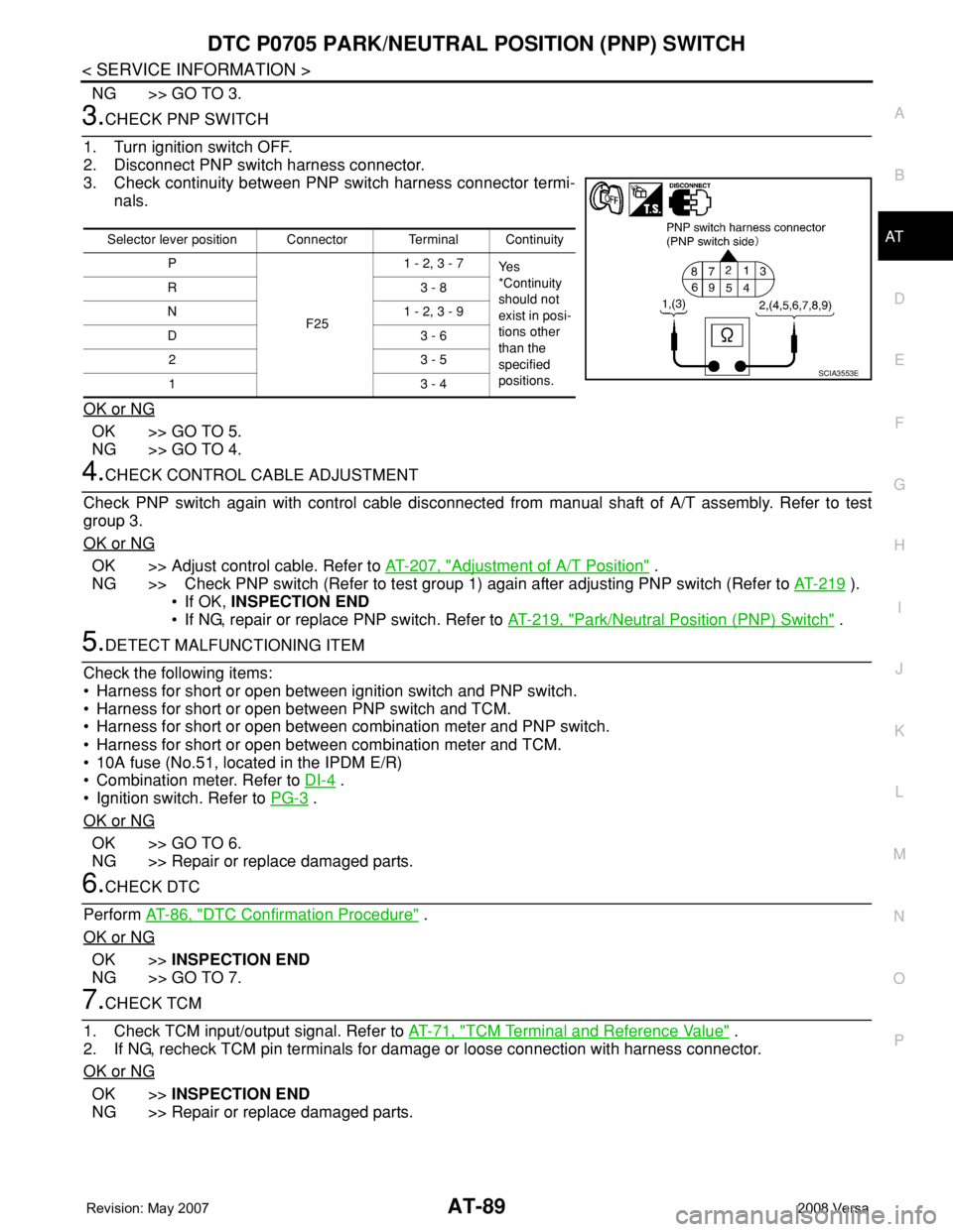
3. Check continuity between PNP switch harness connector termi-
nals.
OK or NG
OK >> GO TO 5.
NG >> GO TO 4.
4.CHECK CONTROL CABLE ADJUSTMENT
Check PNP switch again with control cable disconnected from manual shaft of A/T assembly. Refer to test
group 3.
OK or NG
OK >> Adjust control cable. Refer to AT-207, "Adjustment of A/T Position" .
NG >> Check PNP switch (Refer to test group 1) again after adjusting PNP switch (Refer to AT-219
).
• If OK, INSPECTION END
• If NG, repair or replace PNP switch. Refer to AT-219, "
Park/Neutral Position (PNP) Switch" .
5.DETECT MALFUNCTIONING ITEM
Check the following items:
• Harness for short or open between ignition switch and PNP switch.
• Harness for short or open between PNP switch and TCM.
• Harness for short or open between combination meter and PNP switch.
• Harness for short or open between combination meter and TCM.
• 10A fuse (No.51, located in the IPDM E/R)
• Combination meter. Refer to DI-4
.
• Ignition switch. Refer to PG-3
.
OK or NG
OK >> GO TO 6.
NG >> Repair or replace damaged parts.
6.CHECK DTC
Perform AT-86, "
DTC Confirmation Procedure" .
OK or NG
OK >>INSPECTION END
NG >> GO TO 7.
7.CHECK TCM
1. Check TCM input/output signal. Refer to AT-71, "
TCM Terminal and Reference Value" .
2. If NG, recheck TCM pin terminals for damage or loose connection with harness connector.
OK or NG
OK >>INSPECTION END
NG >> Repair or replace damaged parts.
Selector lever position Connector Terminal Continuity
P
F251 - 2, 3 - 7
Ye s
*Continuity
should not
exist in posi-
tions other
than the
specified
positions. R3 - 8
N 1 - 2, 3 - 9
D3 - 6
23 - 5
13 - 4
SCIA3553E
Page 108 of 2771
AT-96
< SERVICE INFORMATION >
DTC P0720 VEHICLE SPEED SENSOR A/T (REVOLUTION SENSOR)
DTC P0720 VEHICLE SPEED SENSOR A/T (REVOLUTION SENSOR)
DescriptionINFOID:0000000001703217
The revolution sensor detects the revolution of the idler gear parking pawl lock gear and emits a pulse signal.
The pulse signal is sent to the TCM which converts it into vehicle speed.
CONSULT-III Reference Value in Data Monitor ModeINFOID:0000000001703218
Remarks: Specification data are reference values.
On Board Diagnosis LogicINFOID:0000000001703219
• This is an OBD-II self-diagnostic item.
• Diagnostic trouble code “P0720 VHCL SPEED SEN-AT” with CONSULT-III or 1st judgement flicker without
CONSULT-III is detected when TCM does not receive the proper voltage signal from the sensor.
Possible CauseINFOID:0000000001703220
• Harness or connector
(The sensor circuit is open or shorted.)
• Revolution sensor
DTC Confirmation ProcedureINFOID:0000000001703221
CAUTION:
• Always drive vehicle at a safe speed.
• Be careful not to rev engine into the red zone on the tachometer.
• If performing this “DTC Confirmation Procedure” again, always turn ignition switch OFF and wait at
least 10 seconds before continuing.
After the repair, perform the following procedure to confirm the malfunction is eliminated.
WITH CONSULT-III
1. Turn ignition switch ON and select “DATA MONITOR” mode for “A/T” with CONSULT-III.
2. Touch “START”.
3. Drive vehicle and check for an increase of “VHCL/S SE-MTR” value.
If the check result is NG, go to AT-98, "
Diagnosis Procedure" .
If the check result is OK, go to following step.
4. Select “DATA MONITOR” mode for “A/T” with CONSULT-III.
5. Touch “START”.
6. Start engine and maintain the following conditions for at least 5 consecutive seconds.
VEHICLE SPEED: 30 km/h (19 MPH) or more
THROTTLE POSI: More than 1.0/8
SLCT LVR POSI: “D” position
Driving location: Driving the vehicle uphill (increased engine load) will help maintain the driving
conditions required for this test.
If the check result is NG, go to AT-98, "
Diagnosis Procedure" .
If the check result is OK, go to following step.
7. Maintain the following conditions for at least 5 consecutive seconds.
ENGINE SPEED: 3,500 rpm or more
THROTTLE POSI: More than 1.0/8
SLCT LVR POSI: “D” position
Driving location: Driving the vehicle uphill (increased engine load) will help maintain the driving
conditions required for this test.
WITH GST
Follow the procedure “WITH CONSULT-III”.
WITHOUT CONSULT-III
1. Start engine.
Item name Condition Display value
VHCL/S SE-A/T During driving Approximately matches the speedometer reading.