2008 NISSAN TIIDA meter
[x] Cancel search: meterPage 355 of 2771
SERVICE DATA AND SPECIFICATIONS (SDS)
AT-343
< SERVICE INFORMATION >
D
E
F
G
H
I
J
K
L
MA
B
AT
N
O
P
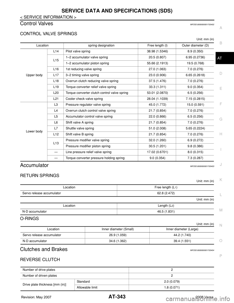
Control ValvesINFOID:0000000001703402
CONTROL VALVE SPRINGS
Unit: mm (in)
AccumulatorINFOID:0000000001703403
RETURN SPRINGS
Unit: mm (in)
Unit: mm (in)
O-RINGS
Unit: mm (in)
Clutches and BrakesINFOID:0000000001703404
REVERSE CLUTCH
Location spring designation Free length (l) Outer diameter (D)
Upper bodyL14 Pilot valve spring 38.98 (1.5346) 8.9 (0.350)
L151–2 accumulator valve spring 20.5 (0.807) 6.95 (0.2736)
1–2 accumulator piston spring 55.66 (2.1913) 19.5 (0.768)
L16 1st reducing valve spring 27.0 (1.063) 7.0 (0.276)
L17 3–2 timing valve spring 23.0 (0.906) 6.65 (0.2618)
L18 Overrun clutch reducing valve spring 37.5 (1.476) 7.0 (0.276)
L19 Torque converter relief valve spring 33.3 (1.311) 9.0 (0.354)
L20 Torque converter clutch control valve spring 53.01 (2.0870) 6.5 (0.256)
L21 Cooler check valve spring 28.04 (1.1039) 7.15 (0.2815)
Lower bodyL3 Pressure regulator valve spring 45.0 (1.772) 15.0 (0.591)
L4 Overrun clutch control valve spring 21.7 (0.854) 7.0 (0.276)
L5 Accumulator control valve spring 22.0 (0.866) 6.5 (0.256)
L6 Shift valve A spring 21.7 (0.854) 7.0 (0.276)
L7 Shuttle valve spring 51.0 (2.008) 5.65 (0.2224)
L12 Shift valve B spring 21.7 (0.854) 7.0 (0.276)
L13Pressure modifier valve spring 32.0 (1.260) 6.9 (0.272)
Pressure modifier piston spring 30.5 (1.201) 9.8 (0.386)
— Line pressure relief valve spring 17.02 (0.6701) 8.0 (0.315)
— Torque converter pressure holding spring 9.0 (0.354) 7.3 (0.287)
Location Free length (L1)
Servo release accumulator 62.8 (2.472)
Location Length (L2)
N-D accumulator46.5 (1.831)
Location Inner diameter (Small) Inner diameter (Large)
Servo release accumulator 26.9 (1.059) 44.2 (1.740)
N-D accumulator 34.6 (1.362) 39.4 (1.551)
Number of drive plates2
Number of driven plates2
Drive plate thickness [mm (in)]Standard 2.0 (0.079)
Allowable limit 1.8 (0.071)
Page 357 of 2771
SERVICE DATA AND SPECIFICATIONS (SDS)
AT-345
< SERVICE INFORMATION >
D
E
F
G
H
I
J
K
L
MA
B
AT
N
O
P
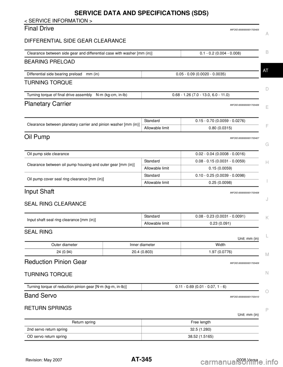
Final DriveINFOID:0000000001703405
DIFFERENTIAL SIDE GEAR CLEARANCE
BEARING PRELOAD
TURNING TORQUE
Planetary CarrierINFOID:0000000001703406
Oil PumpINFOID:0000000001703407
Input ShaftINFOID:0000000001703408
SEAL RING CLEARANCE
SEAL RING
Unit: mm (in)
Reduction Pinion GearINFOID:0000000001703409
TURNING TORQUE
Band ServoINFOID:0000000001703410
RETURN SPRINGS
Unit: mm (in)
Clearance between side gear and differential case with washer [mm (in)] 0.1 - 0.2 (0.004 - 0.008)
Differential side bearing preload mm (in) 0.05 - 0.09 (0.0020 - 0.0035)
Turning torque of final drive assembly N-m (kg-cm, in-lb) 0.68 - 1.26 (7.0 - 13.0, 6.0 - 11.0)
Clearance between planetary carrier and pinion washer [mm (in)]Standard 0.15 - 0.70 (0.0059 - 0.0276)
Allowable limit 0.80 (0.0315)
Oil pump side clearance0.02 - 0.04 (0.0008 - 0.0016)
Clearance between oil pump housing and outer gear [mm (in)]Standard 0.08 - 0.15 (0.0031 - 0.0059)
Allowable limit 0.15 (0.0059)
Oil pump cover seal ring clearance [mm (in)]Standard 0.10 - 0.25 (0.0039 - 0.0098)
Allowable limit 0.25 (0.0098)
Input shaft seal ring clearance [mm (in)]Standard 0.08 - 0.23 (0.0031 - 0.0091)
Allowable limit 0.23 (0.091)
Outer diameter Inner diameter Width
24 (0.94) 20.4 (0.803) 1.97 (0.0776)
Turning torque of reduction pinion gear [N·m (kg-m, in-lb)] 0.11 - 0.69 (0.01 - 0.07, 1 - 6)
Return spring Free length
2nd servo return spring 32.5 (1.280)
OD servo return spring 38.52 (1.5165)
Page 358 of 2771

AT-346
< SERVICE INFORMATION >
SERVICE DATA AND SPECIFICATIONS (SDS)
Output Shaft
INFOID:0000000001703411
SEAL RING CLEARANCE
SEAL RING
Unit: mm (in)
END PLAY
Bearing RetainerINFOID:0000000001703412
SEAL RING CLEARANCE
Total End PlayINFOID:0000000001703413
Reverse Clutch End PlayINFOID:0000000001703414
Removal and InstallationINFOID:0000000001703415
Shift Solenoid ValvesINFOID:0000000001703416
Solenoid ValvesINFOID:0000000001703417
Output shaft seal ring clearance [mm (in)]Standard 0.10 - 0.25 (0.0039 - 0.0098)
Allowable limit 0.25 (0.0098)
Outer diameter Inner diameter Width
29.5 (1.161) 26.2 (1.031) 1.95 (0.0768)
Output shaft end play mm (in) 0 - 0.5 (0 - 0.020)
Bearing retainer seal ring clearance [mm (in)]Standard 0.10 - 0.27 (0.0039 - 0.0106)
Allowable limit 0.27 (0.0106)
Total end play [mm (in)] 0.25 - 0.55 (0.0098 - 0.0217)
Reverse clutch end play [mm (in)] 0.65 - 1.0 (0.0256 - 0.039)
Distance between end of converter housing and torque converter [mm (in)] 14.4 (0.567)
Gear position 1 2 3 4
Shift solenoid valve A ON (Closed) OFF (Open) OFF (Open) ON (Closed)
Shift solenoid valve B ON (Closed)ON (Closed) OFF (Open) OFF (Open)
Solenoid valve designation Resistance (Approx.) Terminal
Shift solenoid valve A 20 - 30 Ω2
Shift solenoid valve B 5 - 20 Ω1
Overrun clutch solenoid valve 20 - 30 Ω3
Line pressure solenoid valve 2.5 - 5.0 Ω4
Torque converter clutch solenoid valve 5 - 20 Ω5
Page 421 of 2771
BCM (BODY CONTROL MODULE)
BCS-5
< SERVICE INFORMATION >
C
D
E
F
G
H
I
J
L
MA
B
BCS
N
O
P
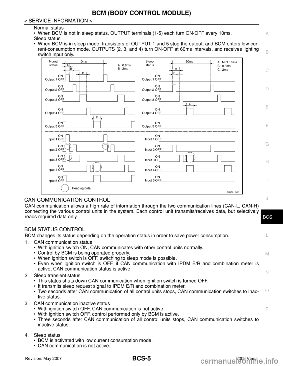
Normal status
• When BCM is not in sleep status, OUTPUT terminals (1-5) each turn ON-OFF every 10ms.
Sleep status
• When BCM is in sleep mode, transistors of OUTPUT 1 and 5 stop the output, and BCM enters low-cur-
rent-consumption mode. OUTPUTS (2, 3, and 4) turn ON-OFF at 60ms intervals, and receives lighting
switch input only.
CAN COMMUNICATION CONTROL
CAN communication allows a high rate of information through the two communication lines (CAN-L, CAN-H)
connecting the various control units in the system. Each control unit transmits/receives data, but selectively
reads required data only.
BCM STATUS CONTROL
BCM changes its status depending on the operation status in order to save power consumption.
1. CAN communication status
• With ignition switch ON, CAN communicates with other control units normally.
• Control by BCM is being operated properly.
• When ignition switch is OFF, switching to sleep mode is possible.
• Even when ignition switch is OFF, if CAN communication with IPDM E/R and combination meter is
active, CAN communication status is active.
2. Sleep transient status
• This status shuts down CAN communication when ignition switch is turned OFF.
• It transmits sleep request signal to IPDM E/R and combination meter.
• Two seconds after CAN communication of all control units stops, CAN communication switches to inac-
tive status.
3. CAN communication inactive status
• With ignition switch OFF, CAN communication is not active.
• With ignition switch OFF, control performed only by BCM is active.
• Three seconds after CAN communication of all control units stops, CAN communication switches to
inactive status.
4. Sleep status
• BCM is activated with low current consumption mode.
• CAN communication is not active.
PKIB6124E
Page 422 of 2771
BCS-6
< SERVICE INFORMATION >
BCM (BODY CONTROL MODULE)
• When CAN communication operation is detected, it switches to CAN communication status.
• When a state of the following switches changes, it switches to CAN communication state:
- Ignition switch
- Key switch (without Intelligent Key)
- Key switch and ignition knob switch (with Intelligent Key)
- Hazard switch
- Door lock/unlock switch
- Front door switch (LH, RH)
- Rear door switch (LH, RH)
- Back door lock assembly (Hatchback)
- Trunk key cylinder switch (Sedan)
- Trunk lamp switch and trunk release solenoid (Sedan)
- Combination switch (passing, lighting switch 1st position, front fog lamp)
- Keyfob (lock/unlock signal)
- Front door key cylinder switch LH
• When control performed only by BCM is required by switch, it shifts to CAN communication inactive
mode.
• Status of combination switch reading function is changed.
SYSTEMS CONTROLLED BY BCM DIRECTLY
• Power door lock system. Refer to BL-22 .
• Remote keyless entry system. Refer to BL-51
.
• Power window system. Refer to GW-18
. NOTE
• Sunroof system. Refer to RF-10. NOTE
• Room lamp timer. Refer to LT- 8 9 .
• Rear wiper and washer system. Refer to WW-24
.
NOTE:
Power supply only. No system control.
SYSTEMS CONTROLLED BY BCM AND IPDM E/R
• Panic system. Refer to BL-51 .
• Vehicle security (theft warning) system. Refer to BL-187
.
• NVIS(NATS) system. Refer to BL-210
.
• Headlamp, tail lamp and battery saver control systems. Refer to LT- 7 2
, LT- 4 or LT- 2 5 .
• Front fog lamp. Refer to LT- 3 9
.
• Front wiper and washer system. Refer to WW-3
.
• Rear window defogger system. Refer to GW-49
.
SYSTEMS CONTROLLED BY BCM AND COMBINATION METER
• Warning chime. Refer to DI-41 .
• Turn signal and hazard warning lamps. Refer to LT- 4 8
.
SYSTEMS CONTROLLED BY BCM AND INTELLIGENT KEY UNIT
• Intelligent Key system. Refer to BL-74 .
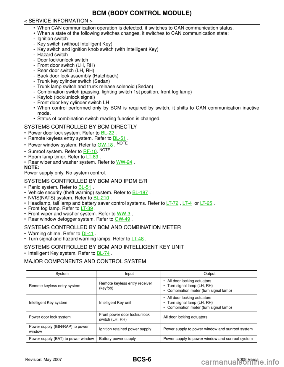
MAJOR COMPONENTS AND CONTROL SYSTEM
System Input Output
Remote keyless entry systemRemote keyless entry receiver
(keyfob)• All door locking actuators
• Turn signal lamp (LH, RH)
• Combination meter (turn signal lamp)
Intelligent Key system Intelligent Key unit• All door locking actuators
• Turn signal lamp (LH, RH)
• Combination meter (turn signal lamp)
Power door lock systemFront power door lock/unlock
switch (LH, RH)All door locking actuators
Power supply (IGN/RAP) to power
windowIgnition retained power supply Power supply to power window and sunroof system
Power supply (BAT) to power window Battery power supply Power supply to power window and sunroof system
Page 423 of 2771

BCM (BODY CONTROL MODULE)
BCS-7
< SERVICE INFORMATION >
C
D
E
F
G
H
I
J
L
MA
B
BCS
N
O
P
CAN Communication System DescriptionINFOID:0000000001704585
Refer to LAN-6, "System Description".
Panic alarm• Key switch
•KeyfobIPDM E/R
Vehicle security system• All door switches
•Keyfob
• Door lock/unlock switch
• Trunk key cylinder switch (Se-
dan)
• Front door key cylinder switch
LH• IPDM/ER
• Security indicator lamp
Battery saver control• Ignition switch
• Combination switchIPDM E/R
Headlamp Combination switch IPDM E/R
Tail lamp Combination switch IPDM E/R
Front fog lamp Combination switch IPDM E/R
Turn signal lamp Combination switch• Turn signal lamp
• Combination meter
Hazard lamp Hazard switch• Turn signal lamp
• Combination meter
Room lamp timer• Key switch
•Keyfob
• Main power window and door
lock/unlock switch
• Front door switch LH
• All door switchInterior room lamp
Back door switch signal (Hatchback) Back door lock assembly Luggage room lamp
Back door lock signal (Hatchback) Back door lock assembly Back door opener
Trunk lamp switch signalTrunk lamp switch and trunk re-
lease solenoidLuggage room lamp
Trunk lid opener signalTrunk lamp switch and trunk re-
lease solenoidTrunk lid opener
Key warning chime• Key switch
• Front door switch LHCombination meter (warning buzzer)
Light warning chime• Combination switch
• Key switch
• Front door switch LHCombination meter (warning buzzer)
Seat belt warning chime• Seat belt buckle switch LH
• Ignition switchCombination meter (warning buzzer)
Front wiper and washer system• Combination switch
• Ignition switchIPDM E/R
Rear window defogger Rear window defogger switch IPDM E/R
Rear wiper and washer system• Combination switch
• Ignition switchRear wiper motor
A/C switch signal Front air control ECM
Blower fan switch signal Front air control ECM
A/C indicator signal Front air control A/C indicator
Low tire pressure warning system Remote keyless entry receiver Combination meterSystem Input Output
Page 433 of 2771
BCM (BODY CONTROL MODULE)
BCS-17
< SERVICE INFORMATION >
C
D
E
F
G
H
I
J
L
MA
B
BCS
N
O
P
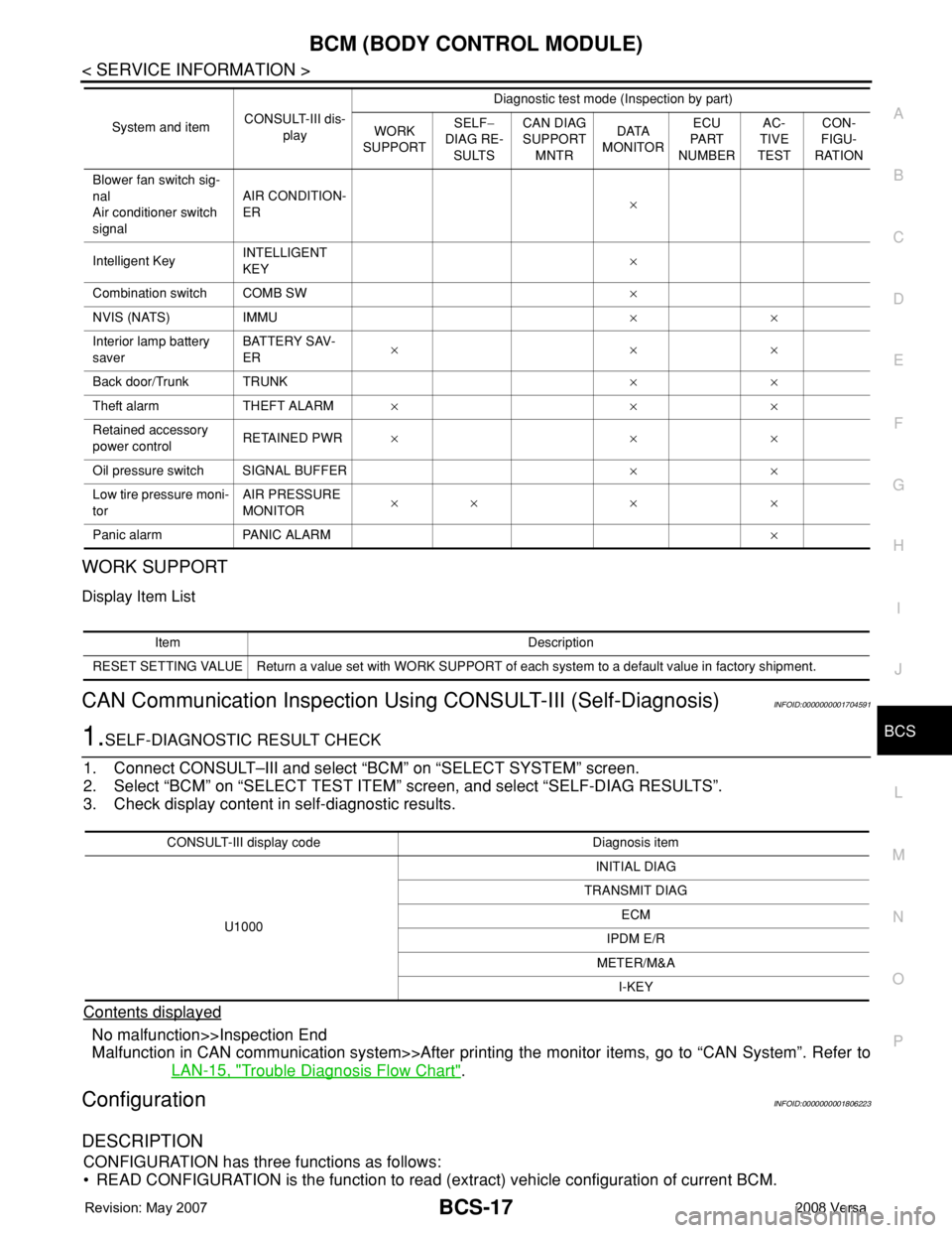
WORK SUPPORT
Display Item List
CAN Communication Inspection Using CONSULT-III (Self-Diagnosis)INFOID:0000000001704591
1.SELF-DIAGNOSTIC RESULT CHECK
1. Connect CONSULT–III and select “BCM” on “SELECT SYSTEM” screen.
2. Select “BCM” on “SELECT TEST ITEM” screen, and select “SELF-DIAG RESULTS”.
3. Check display content in self-diagnostic results.
Contents displayed
No malfunction>>Inspection End
Malfunction in CAN communication system>>After printing the monitor items, go to “CAN System”. Refer to
LAN-15, "
Trouble Diagnosis Flow Chart".
ConfigurationINFOID:0000000001806223
DESCRIPTION
CONFIGURATION has three functions as follows:
• READ CONFIGURATION is the function to read (extract) vehicle configuration of current BCM.
Blower fan switch sig-
nal
Air conditioner switch
signalAIR CONDITION-
ER×
Intelligent KeyINTELLIGENT
KEY×
Combination switch COMB SW×
NVIS (NATS) IMMU××
Interior lamp battery
saverBATTERY SAV-
ER×××
Back door/Trunk TRUNK××
Theft alarm THEFT ALARM×××
Retained accessory
power controlRETAINED PWR×××
Oil pressure switch SIGNAL BUFFER××
Low tire pressure moni-
torAIR PRESSURE
MONITOR×× × ×
Panic alarm PANIC ALARM× System and itemCONSULT-III dis-
playDiagnostic test mode (Inspection by part)
WORK
SUPPORTSELF−
DIAG RE-
SULTSCAN DIAG
SUPPORT
MNTRDATA
MONITORECU
PA R T
NUMBERAC-
TIVE
TESTCON-
FIGU-
RATION
Item Description
RESET SETTING VALUE Return a value set with WORK SUPPORT of each system to a default value in factory shipment.
CONSULT-III display code Diagnosis item
U1000INITIAL DIAG
TRANSMIT DIAG
ECM
IPDM E/R
METER/M&A
I-KEY
Page 436 of 2771

BL-2
ID Code Entry Procedure .......................................71
Keyfob Battery Replacement ..................................73
Removal and Installation of Remote Keyless Entry
Receiver .................................................................
73
INTELLIGENT KEY SYSTEM ............................74
Component Parts and Harness Connector Loca-
tion ..........................................................................
74
System Description .................................................76
CAN Communication System Description ..............83
Schematic ...............................................................84
Wiring Diagram - I/KEY - ........................................86
Intelligent Key Unit Harness Connector Terminal
Layout .....................................................................
96
Terminal and Reference Value for Intelligent Key
Unit .........................................................................
96
Steering Lock Solenoid Harness Connector Ter-
minal Layout ...........................................................
98
Terminal and Reference Value for Steering Lock
Solenoid ..................................................................
98
Terminal and Reference Value for BCM .................99
Trouble Diagnosis Procedure .................................99
CONSULT-III Functions (INTELLIGENT KEY) ......100
CONSULT-III Application Item ...............................101
Trouble Diagnosis Symptom Chart ........................103
CAN Communication System Inspection ...............109
Power Supply and Ground Circuit Inspection ........110
Key Switch (Intelligent Key Unit Input) Check .......110
Key Switch (BCM Input) Check .............................112
Ignition Knob Switch Check ...................................113
Door Switch Check (Hatchback) ............................114
Door Switch Check (Sedan) ..................................117
Door Request Switch Check ..................................118
Back Door Request Switch Check (Hatchback) ....120
Trunk Opener Request Switch Check (Sedan) .....122
Unlock Sensor Check ............................................124
Intelligent Key Warning Buzzer(s) Check ..............125
Outside Key Antenna (Driver Side and Passenger
Side) Check ...........................................................
126
Outside Key Antenna (Rear Bumper) Check .........128
Inside Key Antenna Check ....................................129
Steering Lock Solenoid Check ..............................131
Key Interlock Solenoid (With M/T) Check ..............133
Ignition Switch Position Check ..............................134
Stop Lamp Switch Check (With CVT) ....................134
Stop Lamp Switch Check (With M/T) .....................135
Check CVT Device (Park Position Switch) Check ..136
"P-SHIFT" Warning Lamp (With CVT) Check ........138
"LOCK" Warning Lamp (With M/T) Check .............138
"KEY" Warning Lamp (RED) Check ......................139
"KEY" Warning Lamp (GREEN) Check .................139
Check Warning Chime in Combination Meter ........140
Hazard Function Check .........................................140
Horn Function Check .............................................140
Headlamp Function Check ....................................141
Intelligent Key Battery Replacement .....................142
Remote Keyless Entry Function ............................142
Removal and Installation of Intelligent Key Unit ....142
DOOR ...............................................................144
Fitting Adjustment .................................................144
Removal and Installation .......................................147
FRONT DOOR LOCK .......................................150
Component Parts Location ...................................150
Removal and Installation .......................................150
REAR DOOR LOCK .........................................153
Component Parts Location ...................................153
Removal and Installation .......................................153
BACK DOOR LOCK .........................................156
Component Parts and Harness Connector Loca-
tion ........................................................................
156
System Description ...............................................156
Wiring Diagram - B/DOOR - ..................................157
Terminal and Reference Value for BCM ...............158
Terminal and Reference Value for Intelligent Key
Unit ........................................................................
158
CONSULT-III Function (BCM) ..............................159
Work Flow .............................................................159
Trouble Diagnosis Chart by Symptom ..................159
BCM Power Supply and Ground Circuit ................160
Check Back Door Opener Switch Circuit (Without
Intelligent Key or Power Windows) .......................
160
Check Back Door Opener Switch Circuit (Without
Intelligent Key, with Power Windows) ...................
162
Check Back Door Opener Switch Circuit (With In-
telligent Key) .........................................................
165
Check Back Door Lock Assembly (Actuator) Cir-
cuit ........................................................................
166
Removal and Installation .......................................168
TRUNK LID .......................................................170
Fitting Adjustment .................................................170
Trunk Lid Assembly ..............................................170
Trunk Lid Lock ......................................................171
Trunk Lid Striker ....................................................171
TRUNK LID OPENER .......................................173
Component Parts and Harness Connector Loca-
tion ........................................................................
173
System Description ...............................................173
Wiring Diagram - TLID - ........................................174
Terminal and Reference Value for BCM ...............175
Terminal and Reference Value for Intelligent Key
Unit ........................................................................
175
CONSULT-III Function (BCM) ..............................176
Work Flow .............................................................176
Trouble Diagnosis Chart by Symptom ..................176
BCM Power Supply and Ground Circuit ................177
Check Trunk Lid Opener Switch Circuit (Without
Intelligent Key or Power Windows) .......................
177
Check Trunk Lid Opener Switch Circuit (Without
Intelligent Key, with Power Windows) ...................
179
Check Trunk Lid Opener Switch Circuit (With Intel-
ligent Key) .............................................................
182
Check Trunk Release Solenoid Circuit .................183