Page 747 of 2771

BR-16
< SERVICE INFORMATION >
BRAKE MASTER CYLINDER
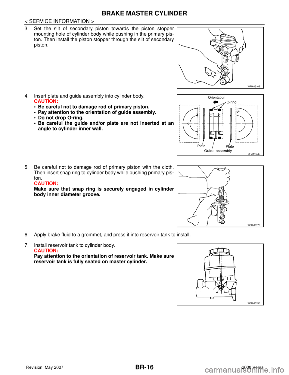
3. Set the slit of secondary piston towards the piston stopper
mounting hole of cylinder body while pushing in the primary pis-
ton. Then install the piston stopper through the slit of secondary
piston.
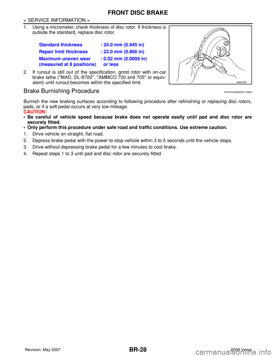
4. Insert plate and guide assembly into cylinder body.
CAUTION:
• Be careful not to damage rod of primary piston.
• Pay attention to the orientation of guide assembly.
• Do not drop O-ring.
• Be careful the guide and/or plate are not inserted at an
angle to cylinder inner wall.
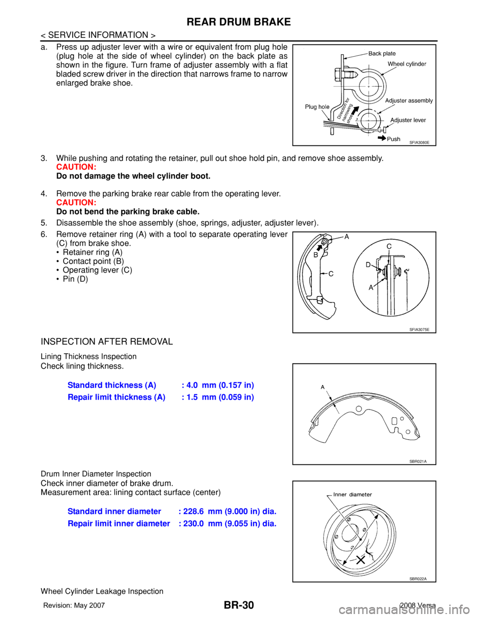
5. Be careful not to damage rod of primary piston with the cloth.
Then insert snap ring to cylinder body while pushing primary pis-
ton.
CAUTION:
Make sure that snap ring is securely engaged in cylinder
body inner diameter groove.
6. Apply brake fluid to a grommet, and press it into reservoir tank to install.
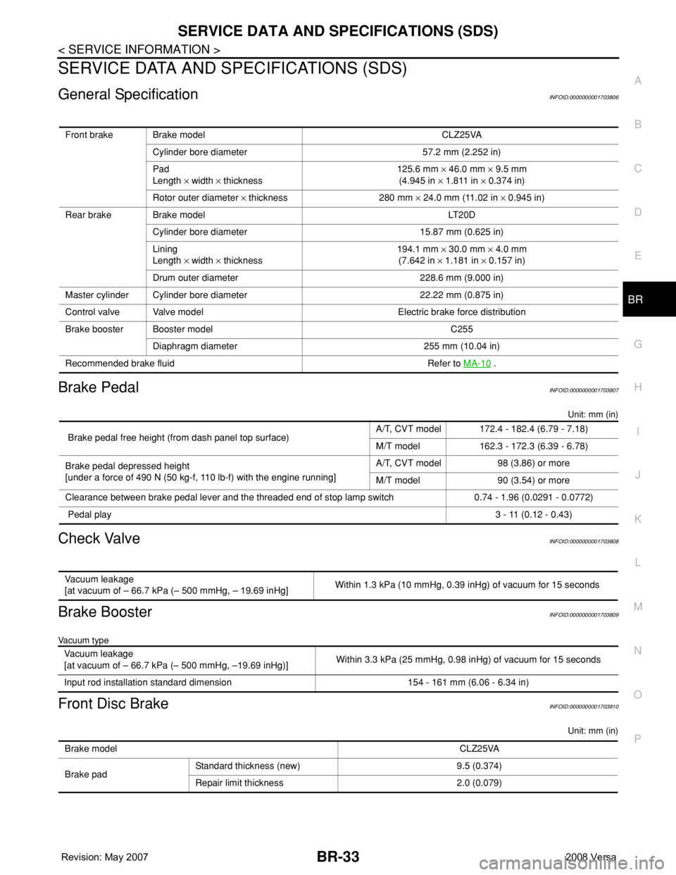
7. Install reservoir tank to cylinder body.
CAUTION:
Pay attention to the orientation of reservoir tank. Make sure
reservoir tank is fully seated on master cylinder.
WFIA0516E
SFIA1469E
WFIA0517E
WFIA0519E
Page 748 of 2771
BRAKE MASTER CYLINDER
BR-17
< SERVICE INFORMATION >
C
D
E
G
H
I
J
K
L
MA
B
BR
N
O
P
8. Secure flange of cylinder body in vise as shown.
CAUTION:
• Use copper plate or cloth to cover flange for securing in
the vise.
• When securing master cylinder assembly in a vise, be
sure not to over-tighten.
• Be sure to secure the flange part with the brake tube
installation side of cylinder body facing up (chamfered pin
insert hole of cylinder body facing up).
9. Using a pin punch [commercial service tool: diameter approx. 4
mm (0.16 in)], insert the reservoir tank pin into the pin hole.
WFIA0514E
WFIA0515E
Page 759 of 2771

BR-28
< SERVICE INFORMATION >
FRONT DISC BRAKE
1. Using a micrometer, check thickness of disc rotor. If thickness is
outside the standard, replace disc rotor.
2. If runout is still out of the specification, grind rotor with on-car
brake lathe (″MAD, DL-8700″, ″AMMCO 700 and 705″ or equiv-
alent) until runout becomes within the specified limit.
Brake Burnishing ProcedureINFOID:0000000001703801
Burnish the new braking surfaces according to following procedure after refinishing or replacing disc rotors,
pads, or if a soft pedal occurs at very low mileage.
CAUTION:
• Be careful of vehicle speed because brake does not operate easily until pad and disc rotor are
securely fitted.
• Only perform this procedure under safe road and traffic conditions. Use extreme caution.
1. Drive vehicle on straight, flat road.
2. Depress brake pedal with the power to stop vehicle within 3 to 5 seconds until the vehicle stops.
3. Drive without depressing brake pedal for a few minutes to cool brake.
4. Repeat steps 1 to 3 until pad and disc rotor are securely fitted.Standard thickness : 24.0 mm (0.945 in)
Repair limit thickness : 22.0 mm (0.866 in)
Maximum uneven wear
(measured at 8 positions): 0.02 mm (0.0008 in)
or less
SBR020B
Page 761 of 2771

BR-30
< SERVICE INFORMATION >
REAR DRUM BRAKE
a. Press up adjuster lever with a wire or equivalent from plug hole
(plug hole at the side of wheel cylinder) on the back plate as
shown in the figure. Turn frame of adjuster assembly with a flat
bladed screw driver in the direction that narrows frame to narrow
enlarged brake shoe.
3. While pushing and rotating the retainer, pull out shoe hold pin, and remove shoe assembly.
CAUTION:
Do not damage the wheel cylinder boot.
4. Remove the parking brake rear cable from the operating lever.
CAUTION:
Do not bend the parking brake cable.
5. Disassemble the shoe assembly (shoe, springs, adjuster, adjuster lever).
6. Remove retainer ring (A) with a tool to separate operating lever
(C) from brake shoe.
• Retainer ring (A)
• Contact point (B)
• Operating lever (C)
•Pin (D)
INSPECTION AFTER REMOVAL
Lining Thickness Inspection
Check lining thickness.
Drum Inner Diameter Inspection
Check inner diameter of brake drum.
Measurement area: lining contact surface (center)
Wheel Cylinder Leakage Inspection
SFIA3080E
SFIA3075E
Standard thickness (A) : 4.0 mm (0.157 in)
Repair limit thickness (A) : 1.5 mm (0.059 in)
SBR021A
Standard inner diameter : 228.6 mm (9.000 in) dia.
Repair limit inner diameter : 230.0 mm (9.055 in) dia.
SBR022A
Page 764 of 2771

SERVICE DATA AND SPECIFICATIONS (SDS)
BR-33
< SERVICE INFORMATION >
C
D
E
G
H
I
J
K
L
MA
B
BR
N
O
P
SERVICE DATA AND SPECIFICATIONS (SDS)
General SpecificationINFOID:0000000001703806
Brake PedalINFOID:0000000001703807
Unit: mm (in)
Check ValveINFOID:0000000001703808
Brake BoosterINFOID:0000000001703809
Vacuum type
Front Disc BrakeINFOID:0000000001703810
Unit: mm (in)
Front brake Brake model CLZ25VA
Cylinder bore diameter 57.2 mm (2.252 in)
Pad
Length × width × thickness125.6 mm × 46.0 mm × 9.5 mm
(4.945 in × 1.811 in × 0.374 in)
Rotor outer diameter × thickness 280 mm × 24.0 mm (11.02 in × 0.945 in)
Rear brake Brake model LT20D
Cylinder bore diameter 15.87 mm (0.625 in)
Lining
Length × width × thickness194.1 mm × 30.0 mm × 4.0 mm
(7.642 in × 1.181 in × 0.157 in)
Drum outer diameter 228.6 mm (9.000 in)
Master cylinder Cylinder bore diameter 22.22 mm (0.875 in)
Control valve Valve model Electric brake force distribution
Brake booster Booster model C255
Diaphragm diameter 255 mm (10.04 in)
Recommended brake fluid Refer to MA-10
.
Brake pedal free height (from dash panel top surface)A/T, CVT model 172.4 - 182.4 (6.79 - 7.18)
M/T model 162.3 - 172.3 (6.39 - 6.78)
Brake pedal depressed height
[under a force of 490 N (50 kg-f, 110 lb-f) with the engine running]A/T, CVT model 98 (3.86) or more
M/T model 90 (3.54) or more
Clearance between brake pedal lever and the threaded end of stop lamp switch 0.74 - 1.96 (0.0291 - 0.0772)
Pedal play3 - 11 (0.12 - 0.43)
Vacuum leakage
[at vacuum of – 66.7 kPa (– 500 mmHg, – 19.69 inHg]Within 1.3 kPa (10 mmHg, 0.39 inHg) of vacuum for 15 seconds
Vacuum leakage
[at vacuum of – 66.7 kPa (– 500 mmHg, –19.69 inHg)]Within 3.3 kPa (25 mmHg, 0.98 inHg) of vacuum for 15 seconds
Input rod installation standard dimension 154 - 161 mm (6.06 - 6.34 in)
Brake modelCLZ25VA
Brake padStandard thickness (new) 9.5 (0.374)
Repair limit thickness 2.0 (0.079)
Page 765 of 2771
BR-34
< SERVICE INFORMATION >
SERVICE DATA AND SPECIFICATIONS (SDS)
Rear Drum Brake
INFOID:0000000001703811
Unit: mm (in)
Disc rotorStandard thickness (new) 24.0 (0.945)
Repair limit thickness 22.0 (0.866)
Runout limit 0.04 (0.0016)
Maximum uneven wear (mea-
sured at 8 positions)0.02 mm (0.0008 in) or less
Brake modelLT 2 0 D
Brake liningStandard thickness (new) 4.0 (0.157)
Repair limit thickness 1.5 (0.059)
DrumStandard inner diameter (new) 228.6 (9.000)
Repair limit inner diameter 230.0 (9.055)
Page 776 of 2771
TROUBLE DIAGNOSIS
BRC-11
< SERVICE INFORMATION >[ABS]
C
D
E
G
H
I
J
K
L
MA
B
BRC
N
O
P
Component Parts and Harness Connector LocationINFOID:0000000001703832
1. Front wheel sensor
LH E51
RH E522. Rear wheel sensor
LH B123
RH B1243. ABS actuator and electric unit (con-
trol unit) E33
4. Combination meter M24
WFIA0497E
Page 782 of 2771
![NISSAN TIIDA 2008 Service Repair Manual TROUBLE DIAGNOSIS
BRC-17
< SERVICE INFORMATION >[ABS]
C
D
E
G
H
I
J
K
L
MA
B
BRC
N
O
P
• If ABS actuator and electric unit (control unit) connection is loose, tighten the piping to the specified
tor NISSAN TIIDA 2008 Service Repair Manual TROUBLE DIAGNOSIS
BRC-17
< SERVICE INFORMATION >[ABS]
C
D
E
G
H
I
J
K
L
MA
B
BRC
N
O
P
• If ABS actuator and electric unit (control unit) connection is loose, tighten the piping to the specified
tor](/manual-img/5/57399/w960_57399-781.png)
TROUBLE DIAGNOSIS
BRC-17
< SERVICE INFORMATION >[ABS]
C
D
E
G
H
I
J
K
L
MA
B
BRC
N
O
P
• If ABS actuator and electric unit (control unit) connection is loose, tighten the piping to the specified
torque and recheck for leaks.
• If there is damage to the connection flare nut or ABS actuator and electric unit (control unit) threads,
replace the damaged part and recheck for leaks.
• When there is fluid leaking or seeping from a fluid connection, use a clean cloth to wipe off the fluid and
recheck for leaks. If fluid is still seeping out, replace the damaged part. If the fluid is leaking at the ABS
actuator and electric unit (control unit), replace the ABS actuator and electric unit (control unit) assem-
bly.
CAUTION:
The ABS actuator and electric unit (control unit) cannot be disassembled and must be replaced
as an assembly.
3. Check the brake pads for excessive wear.
POWER SYSTEM TERMINAL LOOSENESS AND BATTERY INSPECTION
Make sure the battery positive cable, negative cable and ground connection are not loose. In addition, make
sure the battery is sufficiently charged.
ABS WARNING LAMP INSPECTION
1. Make sure ABS warning lamp turns on for approximately 2 seconds when the ignition switch is turned ON.
If it does not, check CAN communications. If there are no errors with the CAN communication system,
replace the combination meter. Refer to IP-11, "
Removal and Installation".
2. Make sure the lamp turns off approximately 2 seconds after the ignition switch is turned ON. If the lamp
does not turn off, conduct self-diagnosis of ABS actuator and electric unit (control unit). If no malfunctions
are detected in self-diagnosis, replace combination meter. Refer to IP-11, "
Removal and Installation".
3. After conducting the self-diagnosis, be sure to erase the error memory. Refer to BRC-18, "
CONSULT-III
Function (ABS)".
Warning Lamp and Indicator TimingINFOID:0000000001703836
Note 1: Brake warning lamp will turn on when the parking brake is applied or when the brake fluid level is low.
x: ON
–: OFF
Control Unit Input/Output Signal StandardINFOID:0000000001703837
REFERENCE VALUE FROM CONSULT-III
CAUTION:
The display shows the control unit calculation data, so a normal value might be displayed even in the
event the output circuit (harness) is open or short circuited.
ConditionABS
warning lampBRAKE
warning lamp
[Note 1]Remarks
When the ignition switch is OFF – – –
After the ignition switch is turned ON for approx. 1
second××–
After the ignition switch is turned ON for approx. 2
seconds––Lamp goes off approx. 2 seconds after the
engine is started.
ABS malfunction×––
EBD malfunction××–