2008 NISSAN TIIDA wheel alignment
[x] Cancel search: wheel alignmentPage 4 of 2771

2008
QUICK REFERENCE CHART: VERSA
QUICK REFERENCE CHART: VERSA
Engine Tune-up DataINFOID:0000000001903528
GENERAL SPECIFICATIONS
SPARK PLUG
Unit: mm (in)
Front Wheel Alignment (Unladen*)INFOID:0000000001903529
Engine typeMR18DE
Cylinder arrangement In-line 4
Displacement cm
3 (cu in)1,797 (109.65)
Bore and stroke mm (in) 84.0 x 81.1 (3.307 x 3.192)
Valve arrangement DOHC
Firing order 1-3-4-2
Number of piston rings Compression 2
Oil 1
Compression ratio 9.9
Compression pressure
kPa (bar, kg/cm
2 , psi) / 250 rpm Standard 1,500 (15.0, 15.3, 217.6)
Minimum 1,200 (12.0, 12.2, 174)
Differential limit between cylinders 100 (1.0, 1.0, 15)
Plug type
Iridium-tipped TYPE
Make DENSO
Standard type FXE20HR11
Spark plug gap Nominal: 1.1 (0.043)
Camber
Degree minute (Decimal degree)RH
Minimum - 1
° 05 ′ (- 1.08 °)
Nominal - 0 ° 20 ′ (- 0.33 °)
Maximum 0 ° 25 ′ (0.42 °)
LH Minimum - 0
° 55 ′ (- 0.92 °)
Nominal - 0 ° 10 ′ (- 0.17 °)
Maximum 0 ° 35 ′ (0.58 °)
Left and right difference
(RH - LH) Minimum -0
° 45 ′ (-0.75 °) or less
Nominal -0 ° 12 ′ (-0.20 °) or less
Maximum 0 ° 21 ′ (0.35 °) or less
Caster
Degree minute (Decimal degree) RH
Minimum 4
° 05 ′ (4.08 °)
Nominal 4 ° 50 ′ (4.83 °)
Maximum 5 ° 35 ′ (5.58 °)
LH Minimum 3
° 55 ′ (3.92 °)
Nominal 4 ° 40 ′ (4.67 °)
Maximum 5 ° 25 ′ (5.42 °)
Left and right difference
(RH - LH) Minimum -0
° 21 ′ (-0.35 °) or less
Nominal 0 ° 12 ′ (0.20 °) or less
Maximum 0 ° 45 ′ (0.75 °) or less
Page 5 of 2771
QUICK REFERENCE CHART: VERSA
2008
*: Fuel, engine coolant and engine oil full. Spare tire, jack, hand tools and mats in designated positions.
Rear Wheel Alignment (Unladen*)INFOID:0000000001903531
*: Fuel, engine coolant and engine oil full. Spare tire, jack, hand tools and mats in designated positions.
Wheelarch Height (Unladen*)INFOID:0000000001903530
Kingpin inclination
Degree minute (Decimal degree)Minimum 9
° 10 ′ (9.17 °)
Nominal 9 ° 55 ′ (9.92 °)
Maximum 10 ° 40 ′ (10.67 °)
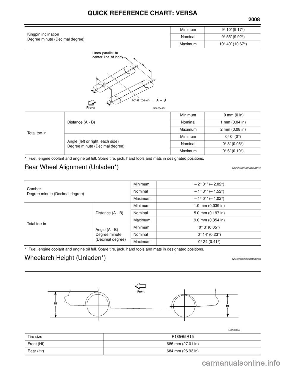
Total toe-in Distance (A - B)
Minimum 0 mm (0 in)
Nominal 1 mm (0.04 in)
Maximum 2 mm (0.08 in)
Angle (left or right, each side)
Degree minute (Decimal degree) Minimum 0
° 0 ′ (0 °)
Nominal 0 ° 3 ′ (0.05 °)
Maximum 0 ° 6 ′ (0.10 °)
SFA234AC
Camber
Degree minute (Decimal degree) Minimum – 2
° 01 ′ (– 2.02 °)
Nominal – 1 ° 31 ′ (– 1.52 °)
Maximum – 1 ° 01 ′ (– 1.02 °)
Total toe-in Distance (A - B)
Minimum 1.0 mm (0.039 in)
Nominal 5.0 mm (0.197 in)
Maximum 9.0 mm (0.354 in)
Angle (A - B)
Degree minute
(Decimal degree) Minimum 0
° 3 ′ (0.05 °)
Nominal 0 ° 14 ′ (0.23 °)
Maximum 0 ° 24 (0.41 °)
Tire size P185/65R15
Front (Hf) 686 mm (27.01 in)
Rear (Hr) 684 mm (26.93 in)
LEIA0085E
Page 805 of 2771

CL-4
< SERVICE INFORMATION >
NOISE, VIBRATION AND HARSHNESS (NVH) TROUBLESHOOTING
NOISE, VIBRATION AND HARSHNESS (NVH) TROUBLESHOOTING
NVH Troubleshooting ChartINFOID:0000000001703116
Use the chart below to help you find the cause of the symptom. The numbers indicate the order of the inspec-
tion. If necessary, repair or replace these parts.
Reference pageCL-5CL-8EM-72CL-11CL-13EM-93
SUSPECTED PARTS (Possible cause)
CLUTCH PEDAL (Inspection and adjustment)
CLUTCH LINE (Air in line)
ENGINE MOUNTING (Loose)
CSC (Concentric slave cylinder) (Worn, dirty or damaged)
CLUTCH DISC (Out of true)
CLUTCH DISC (Runout is excessive)
CLUTCH DISC (Lining broken)
CLUTCH DISC (Dirty or burned)
CLUTCH DISC (Oily)
CLUTCH DISC (Worn out)
CLUTCH DISC (Hardened)
CLUTCH DISC (Lack of spline grease)
DIAPHRAGM SPRING (Damaged)
DIAPHRAGM SPRING (Out of tip alignment)
PRESSURE PLATE (Distortion)
FLYWHEEL (Distortion)
SymptomClutch grabs/chatters 1 2 2 2 2 2
Clutch pedal spongy 1
Clutch noisy 1
Clutch slips 1 2 2 3 4 5
Clutch does not disengage 12 55555 5667
Page 1802 of 2771
FAX-6
< SERVICE INFORMATION >
FRONT WHEEL HUB AND KNUCKLE
2. Without disassembling the hydraulic lines, remove the torque member bolts using power tool. Then repo-
sition the torque member and brake caliper assembly aside with wire. Refer to BR-23
.
CAUTION:
Do not depress brake pedal while brake caliper is removed.
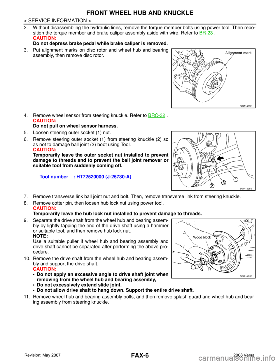
3. Put alignment marks on disc rotor and wheel hub and bearing
assembly, then remove disc rotor.
4. Remove wheel sensor from steering knuckle. Refer to BRC-32
.
CAUTION:
Do not pull on wheel sensor harness.
5. Loosen steering outer socket (1) nut.
6. Remove steering outer socket (1) from steering knuckle (2) so
as not to damage ball joint (3) boot using Tool.
CAUTION:
Temporarily leave the outer socket nut installed to prevent
damage to threads and to prevent the ball joint remover or
suitable tool from suddenly coming off.
7. Remove transverse link ball joint nut and bolt. Then, remove transverse link from steering knuckle.
8. Remove cotter pin, then loosen hub lock nut using power tool.
CAUTION:
Temporarily leave the hub lock nut installed to prevent damage to threads.
9. Separate the drive shaft from the wheel hub and bearing assem-
bly by lightly tapping the end of the drive shaft using a hammer
or suitable tool, and then remove hub lock nut.
NOTE:
Use a suitable puller if wheel hub and bearing assembly and
drive shaft cannot be separated after performing the above pro-
cedure.
10. Remove the drive shaft from the wheel hub and bearing assem-
bly and support the drive shaft.
CAUTION:
• Do not apply an excessive angle to drive shaft joint when
removing from the wheel hub and bearing assembly,
• Do not excessively extend slide joint.
• Do not allow drive shaft to hang down. Support the entire drive shaft.
11. Remove wheel hub and bearing assembly bolts, and then remove splash guard and wheel hub and bear-
ing assembly from steering knuckle.
SDIA1480E
Tool number : HT72520000 (J-25730-A)
SGIA1298E
SDIA1821E
Page 1803 of 2771
FRONT WHEEL HUB AND KNUCKLE
FAX-7
< SERVICE INFORMATION >
C
E
F
G
H
I
J
K
L
MA
B
FA X
N
O
P
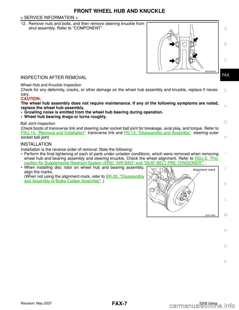
12. Remove nuts and bolts, and then remove steering knuckle from
strut assembly. Refer to "COMPONENT" .
INSPECTION AFTER REMOVAL
Wheel Hub and Knuckle Inspection
Check for any deformity, cracks, or other damage on the wheel hub assembly and knuckle, replace if neces-
sary.
CAUTION:
The wheel hub assembly does not require maintenance. If any of the following symptoms are noted,
replace the wheel hub assembly.
• Growling noise is emitted from the wheel hub bearing during operation.
• Wheel hub bearing drags or turns roughly.
Ball Joint Inspection
Check boots of transverse link and steering outer socket ball joint for breakage, axial play, and torque. Refer to
FSU-14, "
Removal and Installation" transverse link and PS-13, "Disassembly and Assembly" steering outer
socket ball joint.
INSTALLATION
Installation is the reverse order of removal. Note the following:
• Perform the final tightening of each of parts under unladen conditions, which were removed when removing
wheel hub and bearing assembly and steering knuckle. Check the wheel alignment. Refer to RSU-2, "
Pre-
caution for Supplemental Restraint System (SRS) "AIR BAG" and "SEAT BELT PRE-TENSIONER"" .
• When installing disc rotor on wheel hub and bearing assembly,
align the marks.
(When not using the alignment mark, refer to BR-25, "
Disassembly
and Assembly of Brake Caliper Assembly" .)
WDIA0367E
SDIA1480E
Page 1835 of 2771
FSU-1
SUSPENSION
C
D
F
G
H
I
J
K
L
M
SECTION FSU
A
B
FSU
N
O
PCONTENTS
FRONT SUSPENSION
SERVICE INFORMATION ............................2
PRECAUTIONS ...................................................2
Precaution for Supplemental Restraint System
(SRS) "AIR BAG" and "SEAT BELT PRE-TEN-
SIONER" ...................................................................
2
Precaution for Procedure without Cowl Top Cover ......2
Cautions ....................................................................2
PREPARATION ...................................................3
Special Service Tool .................................................3
Commercial Service Tool ..........................................4
NOISE, VIBRATION AND HARSHNESS
(NVH) TROUBLESHOOTING .............................
5
NVH Troubleshooting Chart ......................................5
FRONT SUSPENSION ASSEMBLY ...................6
On-Vehicle Inspection and Service ...........................6
Wheel Alignment Inspection .....................................6
Component ...............................................................9
Removal and Installation .........................................10
COIL SPRING AND STRUT ..............................11
Removal and Installation .........................................11
Disassembly and Assembly .....................................11
TRANSVERSE LINK .........................................14
Removal and Installation .........................................14
STABILIZER BAR .............................................15
Removal and Installation .........................................15
SERVICE DATA AND SPECIFICATIONS
(SDS) .................................................................
16
Wheel Alignment (Unladen*) ...................................16
Ball Joint ..................................................................16
Wheelarch Height (Unladen*) ..................................17
Page 1836 of 2771
FSU-2
< SERVICE INFORMATION >
PRECAUTIONS
SERVICE INFORMATION
PRECAUTIONS
Precaution for Supplemental Restraint System (SRS) "AIR BAG" and "SEAT BELT
PRE-TENSIONER"
INFOID:0000000001703715
The Supplemental Restraint System such as “AIR BAG” and “SEAT BELT PRE-TENSIONER”, used along
with a front seat belt, helps to reduce the risk or severity of injury to the driver and front passenger for certain
types of collision. This system includes seat belt switch inputs and dual stage front air bag modules. The SRS
system uses the seat belt switches to determine the front air bag deployment, and may only deploy one front
air bag, depending on the severity of a collision and whether the front occupants are belted or unbelted.
Information necessary to service the system safely is included in the SRS and SB section of this Service Man-
ual.
WARNING:
• To avoid rendering the SRS inoperative, which could increase the risk of personal injury or death in
the event of a collision which would result in air bag inflation, all maintenance must be performed by
an authorized NISSAN/INFINITI dealer.
• Improper maintenance, including incorrect removal and installation of the SRS, can lead to personal
injury caused by unintentional activation of the system. For removal of Spiral Cable and Air Bag
Module, see the SRS section.
• Do not use electrical test equipment on any circuit related to the SRS unless instructed to in this
Service Manual. SRS wiring harnesses can be identified by yellow and/or orange harnesses or har-
ness connectors.
Precaution for Procedure without Cowl Top CoverINFOID:0000000001703716
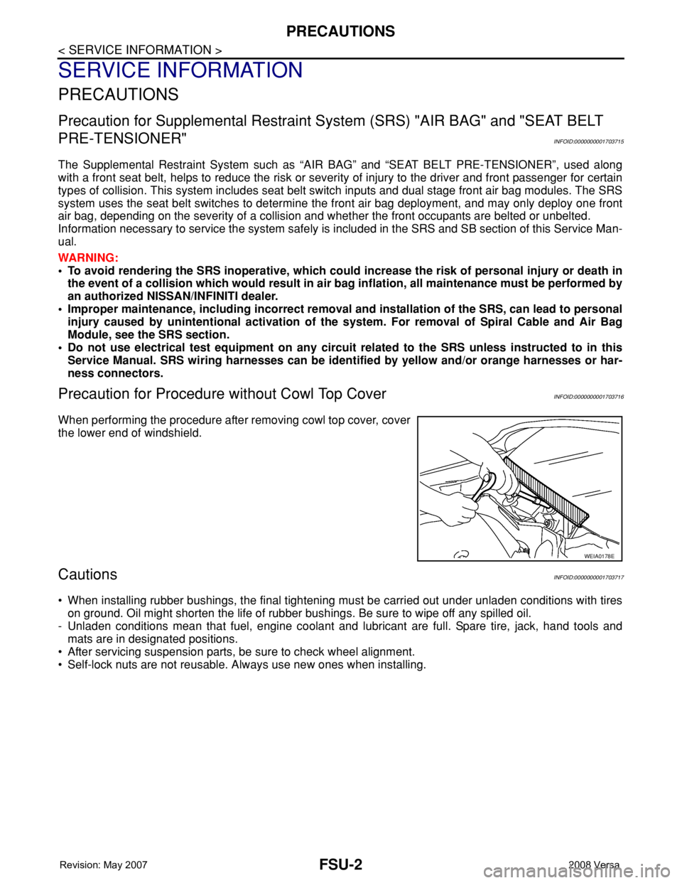
When performing the procedure after removing cowl top cover, cover
the lower end of windshield.
CautionsINFOID:0000000001703717
• When installing rubber bushings, the final tightening must be carried out under unladen conditions with tires
on ground. Oil might shorten the life of rubber bushings. Be sure to wipe off any spilled oil.
- Unladen conditions mean that fuel, engine coolant and lubricant are full. Spare tire, jack, hand tools and
mats are in designated positions.
• After servicing suspension parts, be sure to check wheel alignment.
• Self-lock nuts are not reusable. Always use new ones when installing.
WEIA0178E
Page 1837 of 2771
PREPARATION
FSU-3
< SERVICE INFORMATION >
C
D
F
G
H
I
J
K
L
MA
B
FSU
N
O
P
PREPARATION
Special Service ToolINFOID:0000000001703718
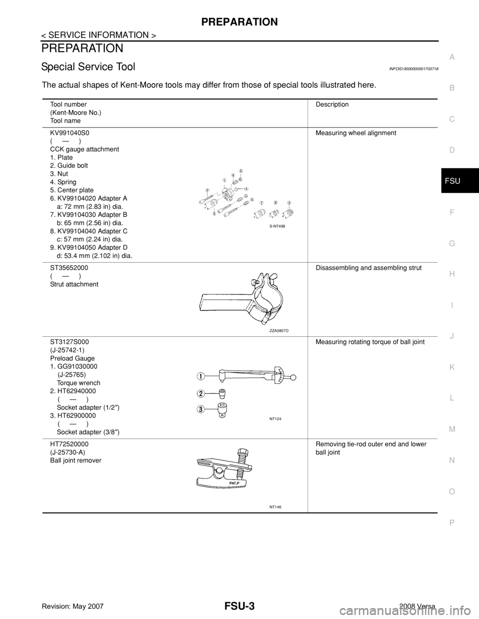
The actual shapes of Kent-Moore tools may differ from those of special tools illustrated here.
Tool number
(Kent-Moore No.)
Tool nameDescription
KV991040S0
(—)
CCK gauge attachment
1. Plate
2. Guide bolt
3. Nut
4. Spring
5. Center plate
6. KV99104020 Adapter A
a: 72 mm (2.83 in) dia.
7. KV99104030 Adapter B
b: 65 mm (2.56 in) dia.
8. KV99104040 Adapter C
c: 57 mm (2.24 in) dia.
9. KV99104050 Adapter D
d: 53.4 mm (2.102 in) dia.Measuring wheel alignment
ST35652000
(—)
Strut attachmentDisassembling and assembling strut
ST3127S000
(J-25742-1)
Preload Gauge
1. GG91030000
(J-25765)
Torque wrench
2. HT62940000
( — )
Socket adapter (1/2″)
3. HT62900000
( — )
Socket adapter (3/8″)Measuring rotating torque of ball joint
HT72520000
(J-25730-A)
Ball joint removerRemoving tie-rod outer end and lower
ball joint
S-NT498
ZZA0807D
NT124
NT146