2008 NISSAN TIIDA Rocker cover
[x] Cancel search: Rocker coverPage 1117 of 2771
POSITIVE CRANKCASE VENTILATION
EC-43
< SERVICE INFORMATION >
C
D
E
F
G
H
I
J
K
L
MA
EC
N
P O
POSITIVE CRANKCASE VENTILATION
DescriptionINFOID:0000000001702570
SYSTEM DESCRIPTION
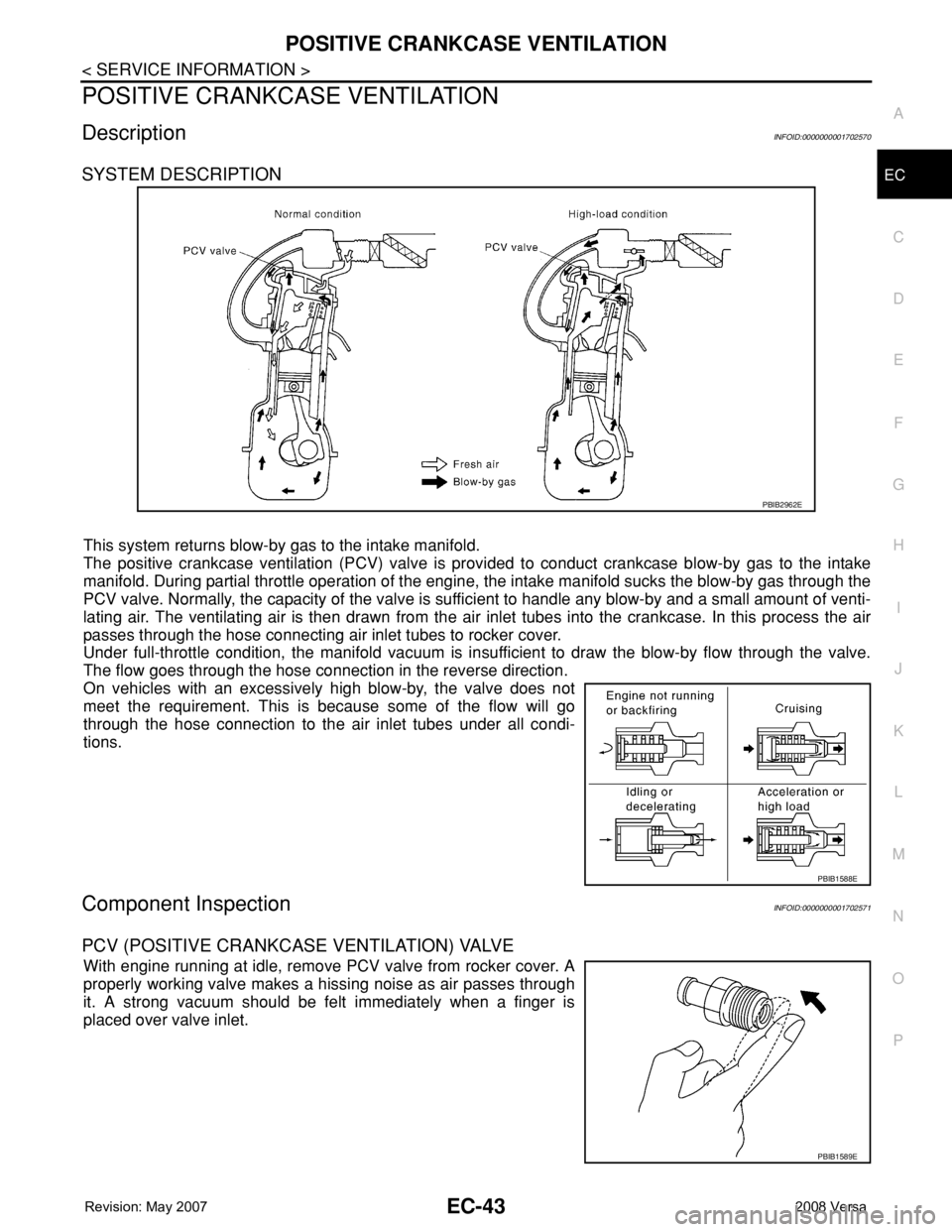
This system returns blow-by gas to the intake manifold.
The positive crankcase ventilation (PCV) valve is provided to conduct crankcase blow-by gas to the intake
manifold. During partial throttle operation of the engine, the intake manifold sucks the blow-by gas through the
PCV valve. Normally, the capacity of the valve is sufficient to handle any blow-by and a small amount of venti-
lating air. The ventilating air is then drawn from the air inlet tubes into the crankcase. In this process the air
passes through the hose connecting air inlet tubes to rocker cover.
Under full-throttle condition, the manifold vacuum is insufficient to draw the blow-by flow through the valve.
The flow goes through the hose connection in the reverse direction.
On vehicles with an excessively high blow-by, the valve does not
meet the requirement. This is because some of the flow will go
through the hose connection to the air inlet tubes under all condi-
tions.
Component InspectionINFOID:0000000001702571
PCV (POSITIVE CRANKCASE VENTILATION) VALVE
With engine running at idle, remove PCV valve from rocker cover. A
properly working valve makes a hissing noise as air passes through
it. A strong vacuum should be felt immediately when a finger is
placed over valve inlet.
PBIB2962E
PBIB1588E
PBIB1589E
Page 1208 of 2771
EC-134
< SERVICE INFORMATION >
TROUBLE DIAGNOSIS - SPECIFICATION VALUE
3. Perform EC-75, "VIN Registration".
4. Perform EC-76, "
Accelerator Pedal Released Position Learning".
5. Perform EC-76, "
Throttle Valve Closed Position Learning".
6. Perform EC-76, "
Idle Air Volume Learning".
>> GO TO 29.
25.CHECK INTAKE SYSTEM
Check for the cause of uneven air flow through mass air flow sensor. Refer to the following.
• Crushed air ducts
• Malfunctioning seal of air cleaner element
• Uneven dirt of air cleaner element
• Improper specification of intake air system
OK or NG
OK >> GO TO 27.
NG >> Repair or replace malfunctioning part, and then GO TO 26.
26.CHECK “B/FUEL SCHDL”
Select “B/FUEL SCHDL” in “DATA MONITOR (SPEC)” mode, and make sure that the indication is within the
SP value.
OK or NG
OK >>INSPECTION END
NG (Less than the SP value)>>GO TO 27.
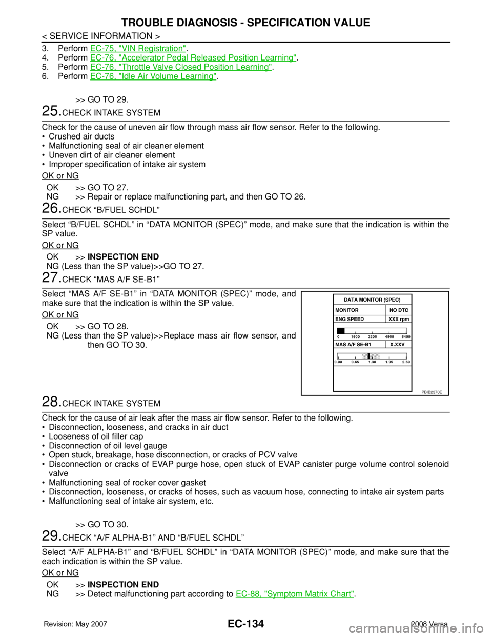
27.CHECK “MAS A/F SE-B1”
Select “MAS A/F SE-B1” in “DATA MONITOR (SPEC)” mode, and
make sure that the indication is within the SP value.
OK or NG
OK >> GO TO 28.
NG (Less than the SP value)>>Replace mass air flow sensor, and
then GO TO 30.
28.CHECK INTAKE SYSTEM
Check for the cause of air leak after the mass air flow sensor. Refer to the following.
• Disconnection, looseness, and cracks in air duct
• Looseness of oil filler cap
• Disconnection of oil level gauge
• Open stuck, breakage, hose disconnection, or cracks of PCV valve
• Disconnection or cracks of EVAP purge hose, open stuck of EVAP canister purge volume control solenoid
valve
• Malfunctioning seal of rocker cover gasket
• Disconnection, looseness, or cracks of hoses, such as vacuum hose, connecting to intake air system parts
• Malfunctioning seal of intake air system, etc.
>> GO TO 30.
29.CHECK “A/F ALPHA-B1” AND “B/FUEL SCHDL”
Select “A/F ALPHA-B1” and “B/FUEL SCHDL” in “DATA MONITOR (SPEC)” mode, and make sure that the
each indication is within the SP value.
OK or NG
OK >>INSPECTION END
NG >> Detect malfunctioning part according to EC-88, "
Symptom Matrix Chart".
PBIB2370E
Page 1689 of 2771
EM-12
< SERVICE INFORMATION >
NOISE, VIBRATION AND HARSHNESS (NVH) TROUBLESHOOTING
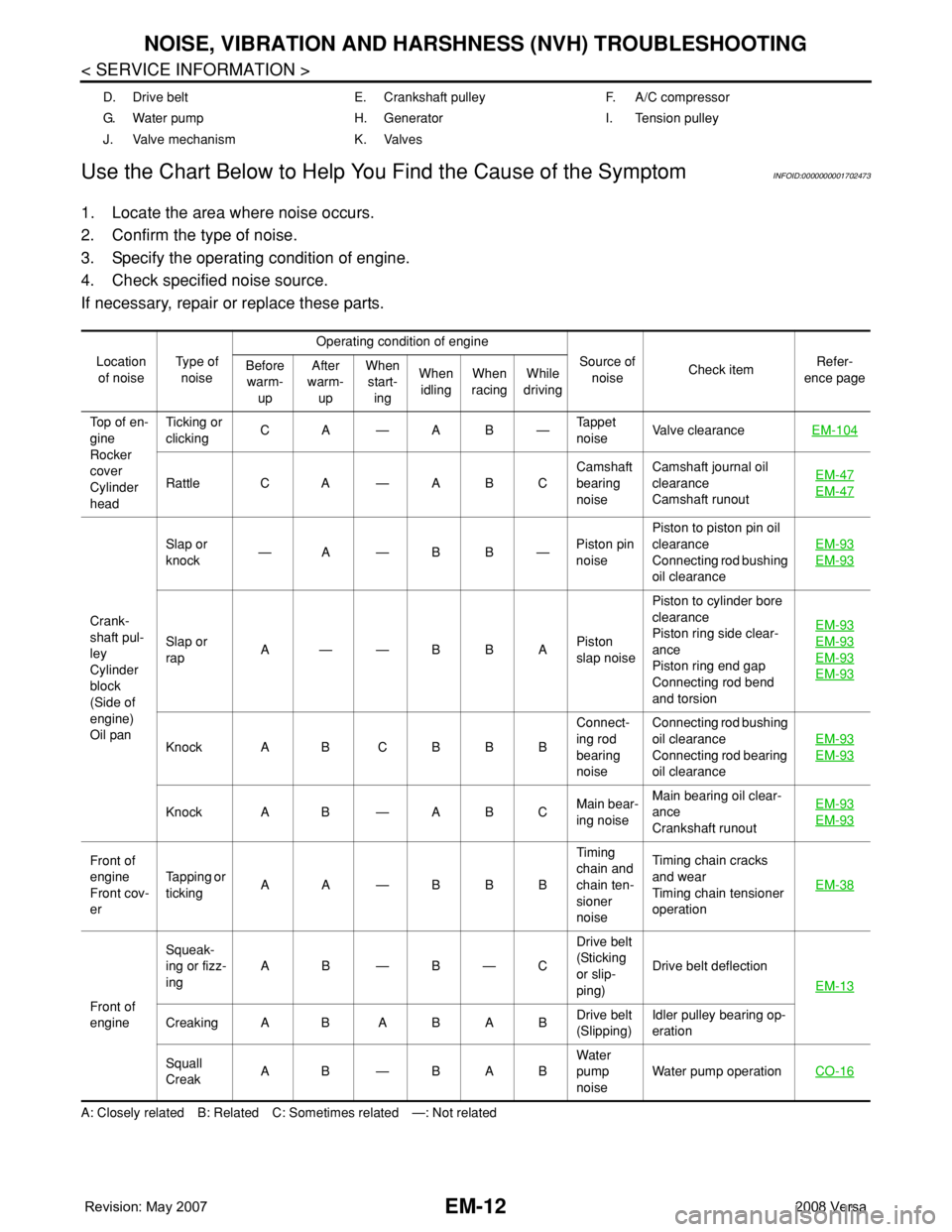
Use the Chart Below to Help You Find the Cause of the Symptom
INFOID:0000000001702473
1. Locate the area where noise occurs.
2. Confirm the type of noise.
3. Specify the operating condition of engine.
4. Check specified noise source.
If necessary, repair or replace these parts.
A: Closely related B: Related C: Sometimes related —: Not relatedD. Drive belt E. Crankshaft pulley F. A/C compressor
G. Water pump H. Generator I. Tension pulley
J. Valve mechanism K. Valves
Location
of noiseTyp e of
noiseOperating condition of engine
Source of
noiseCheck itemRefer-
ence page Before
warm-
upAfter
warm-
upWhen
start-
ingWhen
idlingWhen
racingWhile
driving
Top of en-
gine
Rocker
cover
Cylinder
headTicking or
clickingCA—AB—Tappet
noiseValve clearanceEM-104
Rattle C A — A B CCamshaft
bearing
noiseCamshaft journal oil
clearance
Camshaft runoutEM-47EM-47
Crank-
shaft pul-
ley
Cylinder
block
(Side of
engine)
Oil panSlap or
knock—A—BB—Piston pin
noisePiston to piston pin oil
clearance
Connecting rod bushing
oil clearanceEM-93
EM-93
Slap or
rapA——BBAPiston
slap noisePiston to cylinder bore
clearance
Piston ring side clear-
ance
Piston ring end gap
Connecting rod bend
and torsionEM-93EM-93
EM-93
EM-93
Knock A B C B B BConnect-
ing rod
bearing
noiseConnecting rod bushing
oil clearance
Connecting rod bearing
oil clearanceEM-93EM-93
Knock A B — A B CMain bear-
ing noiseMain bearing oil clear-
ance
Crankshaft runoutEM-93EM-93
Front of
engine
Front cov-
erTapping or
tickingAA—BBBTiming
chain and
chain ten-
sioner
noiseTiming chain cracks
and wear
Timing chain tensioner
operationEM-38
Front of
engineSqueak-
ing or fizz-
ingAB—B—CDrive belt
(Sticking
or slip-
ping)Drive belt deflection
EM-13
Creaking A B A B A BDrive belt
(Slipping)Idler pulley bearing op-
eration
Squall
CreakAB—BABWater
pump
noiseWater pump operationCO-16
Page 1693 of 2771
EM-16
< SERVICE INFORMATION >
AIR CLEANER AND AIR DUCT
AIR CLEANER AND AIR DUCT
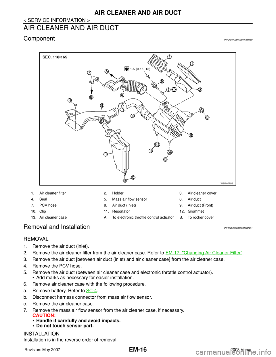
ComponentINFOID:0000000001702480
Removal and InstallationINFOID:0000000001702481
REMOVAL
1. Remove the air duct (inlet).
2. Remove the air cleaner filter from the air cleaner case. Refer to EM-17, "
Changing Air Cleaner Filter".
3. Remove the air duct [between air duct (inlet) and air cleaner case] from the air cleaner case.
4. Remove the PCV hose.
5. Remove the air duct (between air cleaner case and electronic throttle control actuator).
• Add marks as necessary for easier installation.
6. Remove air cleaner case with the following procedure.
a. Remove battery. Refer to SC-4
.
b. Disconnect harness connector from mass air flow sensor.
c. Remove the air cleaner case.
7. Remove the mass air flow sensor from the air cleaner case, if necessary.
CAUTION:
• Handle it carefully and avoid impacts.
• Do not touch sensor part.
INSTALLATION
Installation is in the reverse order of removal.
1. Air cleaner filter 2. Holder 3. Air cleaner cover
4. Seal 5. Mass air flow sensor 6. Air duct
7. PCV hose 8. Air duct (Inlet) 9. Air duct (Front)
10. Clip 11. Resonator 12. Grommet
13. Air cleaner case A. To electronic throttle control actuator B. To rocker cover
WBIA0770E
Page 1707 of 2771
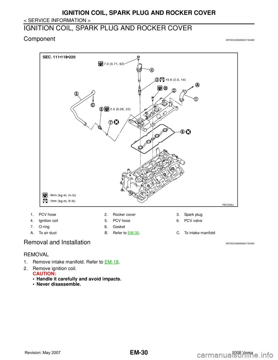
EM-30
< SERVICE INFORMATION >
IGNITION COIL, SPARK PLUG AND ROCKER COVER
IGNITION COIL, SPARK PLUG AND ROCKER COVER
ComponentINFOID:0000000001702489
Removal and InstallationINFOID:0000000001702490
REMOVAL
1. Remove intake manifold. Refer to EM-18.
2. Remove ignition coil.
CAUTION:
• Handle it carefully and avoid impacts.
• Never disassemble.
1. PCV hose 2. Rocker cover 3. Spark plug
4. Ignition coil 5. PCV hose 6. PCV valve
7. O-ring 8. Gasket
A. To air duct B. Refer to EM-30
. C. To intake manifold
PBIC3536J
Page 1708 of 2771
IGNITION COIL, SPARK PLUG AND ROCKER COVER
EM-31
< SERVICE INFORMATION >
C
D
E
F
G
H
I
J
K
L
MA
EM
N
P O
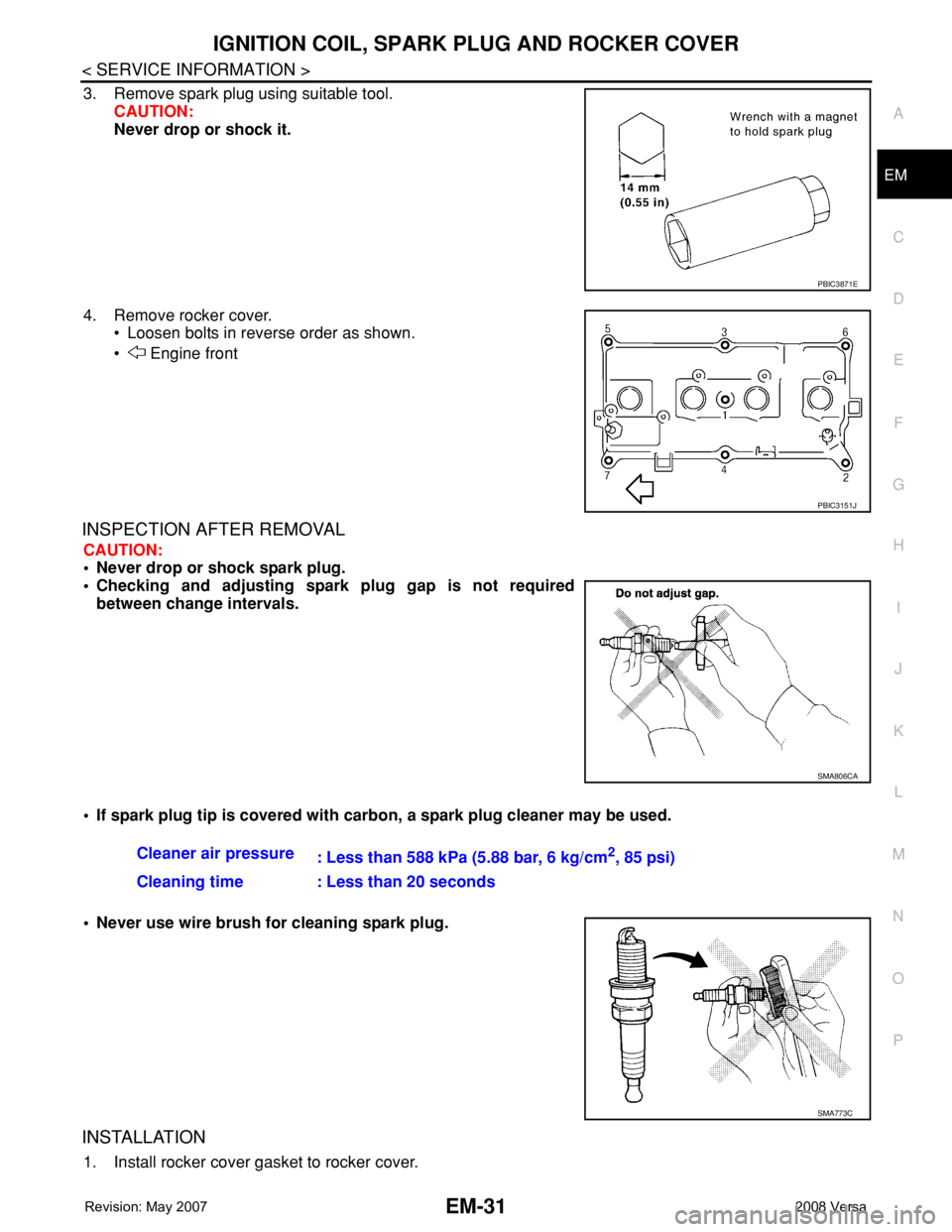
3. Remove spark plug using suitable tool.
CAUTION:
Never drop or shock it.
4. Remove rocker cover.
• Loosen bolts in reverse order as shown.
• Engine front
INSPECTION AFTER REMOVAL
CAUTION:
• Never drop or shock spark plug.
• Checking and adjusting spark plug gap is not required
between change intervals.
• If spark plug tip is covered with carbon, a spark plug cleaner may be used.
• Never use wire brush for cleaning spark plug.
INSTALLATION
1. Install rocker cover gasket to rocker cover.
PBIC3871E
PBIC3151J
SMA806CA
Cleaner air pressure
: Less than 588 kPa (5.88 bar, 6 kg/cm2, 85 psi)
Cleaning time : Less than 20 seconds
SMA773C
Page 1709 of 2771
EM-32
< SERVICE INFORMATION >
IGNITION COIL, SPARK PLUG AND ROCKER COVER
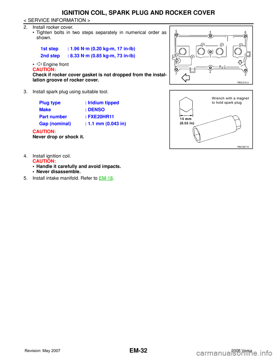
2. Install rocker cover.
• Tighten bolts in two steps separately in numerical order as
shown.
• Engine front
CAUTION:
Check if rocker cover gasket is not dropped from the instal-
lation groove of rocker cover.
3. Install spark plug using suitable tool.
CAUTION:
Never drop or shock it.
4. Install ignition coil.
CAUTION:
• Handle it carefully and avoid impacts.
• Never disassemble.
5. Install intake manifold. Refer to EM-18
. 1st step : 1.96 N·m (0.20 kg-m, 17 in-lb)
2nd step : 8.33 N·m (0.85 kg-m, 73 in-lb)
PBIC3151J
Plug type : Iridium tipped
Make : DENSO
Part number : FXE20HR11
Gap (nominal) : 1.1 mm (0.043 in)
PBIC3871E
Page 1715 of 2771
EM-38
< SERVICE INFORMATION >
TIMING CHAIN
Removal and Installation
INFOID:0000000001844926
CAUTION:
The rotating direction indicated in the text indicates all directions seen from the engine front.
REMOVAL
1. Remove front RH wheel. Refer to WT-6, "Rotation".
2. Remove front fender protector (RH). Refer to EI-23, "
Removal and Installation".
3. Drain engine oil. Refer to LU-7, "
Changing Engine Oil".
NOTE:
Perform this step when engine is cold.
4. Remove the following parts.
• Rocker cover: Refer to EM-30, "
Component".
• Drive belt: Refer to EM-13, "
Removal and Installation".
• Water pump pulley: Refer to CO-16, "
Component".
• Ground cable (between engine bracket (RH) and radiator core support)
5. Support the bottom surface of engine using a transmission jack, and then remove the engine bracket and
insulator (RH). Refer to EM-72, "
Component".
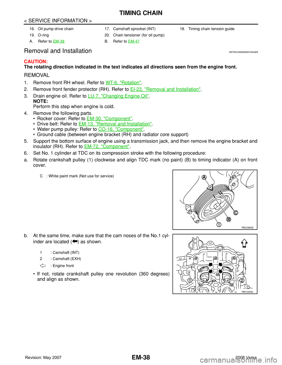
6. Set No. 1 cylinder at TDC on its compression stroke with the following procedure:
a. Rotate crankshaft pulley (1) clockwise and align TDC mark (no paint) (B) to timing indicator (A) on front
cover.
b. At the same time, make sure that the cam noses of the No.1 cyl-
inder are located ( ) as shown.
• If not, rotate crankshaft pulley one revolution (360 degrees)
and align as shown.
16. Oil pump drive chain 17. Camshaft sprocket (INT) 18. Timing chain tension guide
19. O-ring 20. Chain tensioner (for oil pump)
A. Refer to EM-38
B. Refer to EM-47
C : White paint mark (Not use for service)
PBIC3960E
1 : Camshaft (INT)
2 : Camshaft (EXH)
: Engine front
PBIC3359J