2008 NISSAN TIIDA Rocker cover
[x] Cancel search: Rocker coverPage 1724 of 2771
CAMSHAFT
EM-47
< SERVICE INFORMATION >
C
D
E
F
G
H
I
J
K
L
MA
EM
N
P O
CAMSHAFT
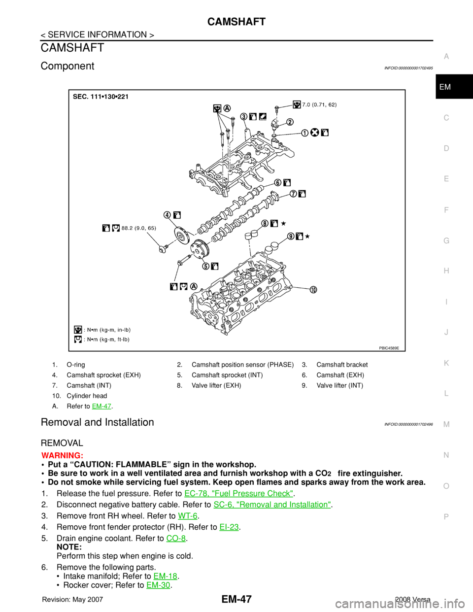
ComponentINFOID:0000000001702495
Removal and InstallationINFOID:0000000001702496
REMOVAL
WARNING:
• Put a “CAUTION: FLAMMABLE” sign in the workshop.
• Be sure to work in a well ventilated area and furnish workshop with a CO
2 fire extinguisher.
• Do not smoke while servicing fuel system. Keep open flames and sparks away from the work area.
1. Release the fuel pressure. Refer to EC-78, "
Fuel Pressure Check".
2. Disconnect negative battery cable. Refer to SC-6, "
Removal and Installation".
3. Remove front RH wheel. Refer to WT-6
.
4. Remove front fender protector (RH). Refer to EI-23
.
5. Drain engine coolant. Refer to CO-8
.
NOTE:
Perform this step when engine is cold.
6. Remove the following parts.
• Intake manifold; Refer to EM-18
.
• Rocker cover; Refer to EM-30
.
1. O-ring 2. Camshaft position sensor (PHASE) 3. Camshaft bracket
4. Camshaft sprocket (EXH) 5. Camshaft sprocket (INT) 6. Camshaft (EXH)
7. Camshaft (INT) 8. Valve lifter (EXH) 9. Valve lifter (INT)
10. Cylinder head
A. Refer to EM-47
.
PBIC4589E
Page 1732 of 2771
CAMSHAFT
EM-55
< SERVICE INFORMATION >
C
D
E
F
G
H
I
J
K
L
MA
EM
N
P O
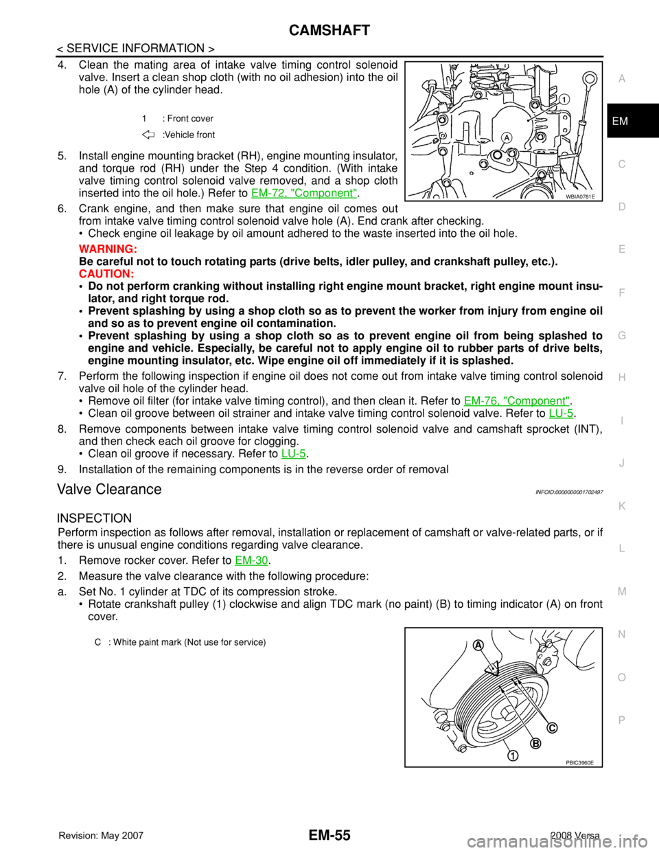
4. Clean the mating area of intake valve timing control solenoid
valve. Insert a clean shop cloth (with no oil adhesion) into the oil
hole (A) of the cylinder head.
5. Install engine mounting bracket (RH), engine mounting insulator,
and torque rod (RH) under the Step 4 condition. (With intake
valve timing control solenoid valve removed, and a shop cloth
inserted into the oil hole.) Refer to EM-72, "
Component".
6. Crank engine, and then make sure that engine oil comes out
from intake valve timing control solenoid valve hole (A). End crank after checking.
• Check engine oil leakage by oil amount adhered to the waste inserted into the oil hole.
WARNING:
Be careful not to touch rotating parts (drive belts, idler pulley, and crankshaft pulley, etc.).
CAUTION:
• Do not perform cranking without installing right engine mount bracket, right engine mount insu-
lator, and right torque rod.
• Prevent splashing by using a shop cloth so as to prevent the worker from injury from engine oil
and so as to prevent engine oil contamination.
• Prevent splashing by using a shop cloth so as to prevent engine oil from being splashed to
engine and vehicle. Especially, be careful not to apply engine oil to rubber parts of drive belts,
engine mounting insulator, etc. Wipe engine oil off immediately if it is splashed.
7. Perform the following inspection if engine oil does not come out from intake valve timing control solenoid
valve oil hole of the cylinder head.
• Remove oil filter (for intake valve timing control), and then clean it. Refer to EM-76, "
Component".
• Clean oil groove between oil strainer and intake valve timing control solenoid valve. Refer to LU-5
.
8. Remove components between intake valve timing control solenoid valve and camshaft sprocket (INT),
and then check each oil groove for clogging.
• Clean oil groove if necessary. Refer to LU-5
.
9. Installation of the remaining components is in the reverse order of removal
Valve ClearanceINFOID:0000000001702497
INSPECTION
Perform inspection as follows after removal, installation or replacement of camshaft or valve-related parts, or if
there is unusual engine conditions regarding valve clearance.
1. Remove rocker cover. Refer to EM-30
.
2. Measure the valve clearance with the following procedure:
a. Set No. 1 cylinder at TDC of its compression stroke.
• Rotate crankshaft pulley (1) clockwise and align TDC mark (no paint) (B) to timing indicator (A) on front
cover.
1 : Front cover
:Vehicle front
WBIA0781E
C : White paint mark (Not use for service)
PBIC3960E
Page 1741 of 2771
EM-64
< SERVICE INFORMATION >
CYLINDER HEAD
• Water outlet; Refer to CO-19.
• Rocker cover; Refer to EM-30
.
• Front cover, timing chain; Refer to EM-37
.
• Camshaft; Refer to EM-47
.
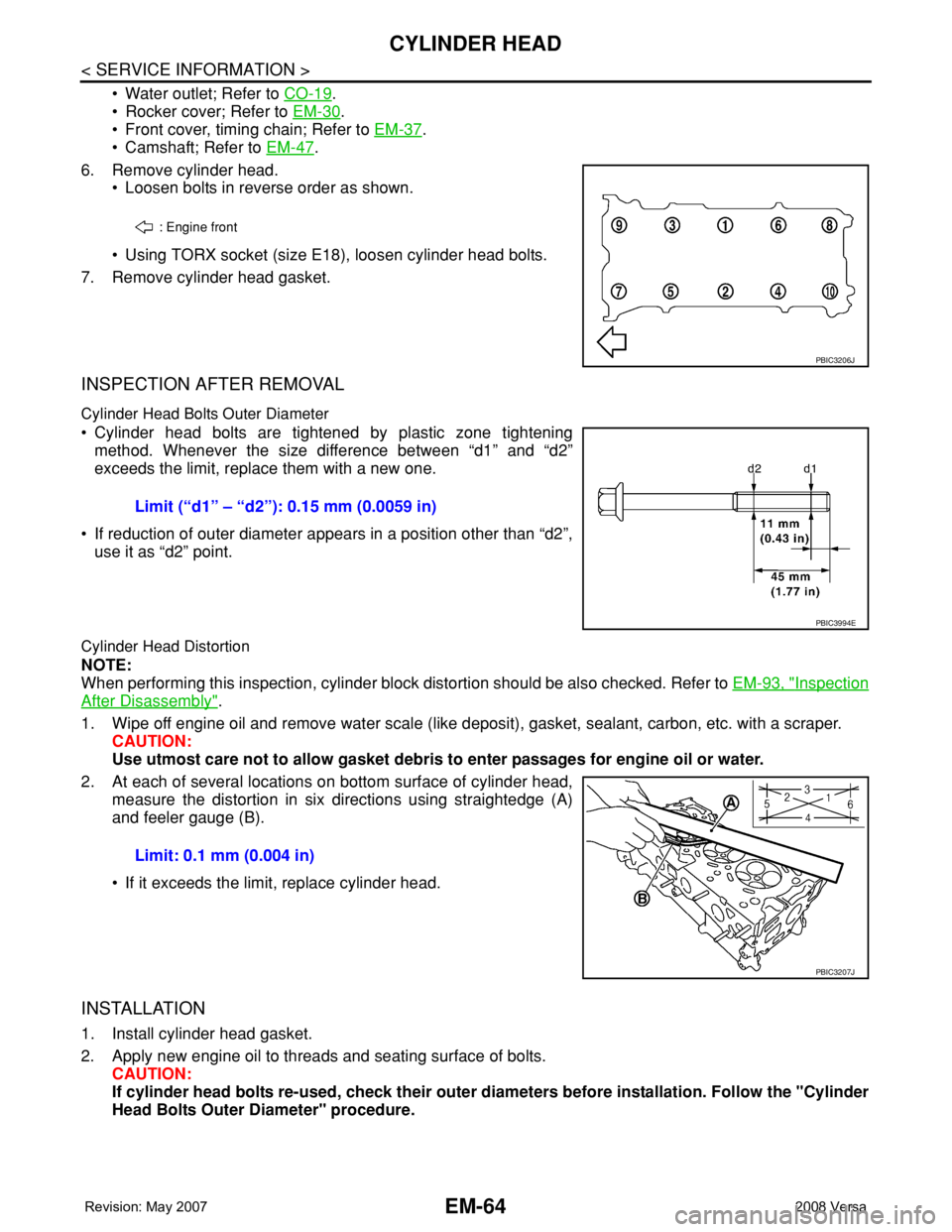
6. Remove cylinder head.
• Loosen bolts in reverse order as shown.
• Using TORX socket (size E18), loosen cylinder head bolts.
7. Remove cylinder head gasket.
INSPECTION AFTER REMOVAL
Cylinder Head Bolts Outer Diameter
• Cylinder head bolts are tightened by plastic zone tightening
method. Whenever the size difference between “d1” and “d2”
exceeds the limit, replace them with a new one.
• If reduction of outer diameter appears in a position other than “d2”,
use it as “d2” point.
Cylinder Head Distortion
NOTE:
When performing this inspection, cylinder block distortion should be also checked. Refer to EM-93, "
Inspection
After Disassembly".
1. Wipe off engine oil and remove water scale (like deposit), gasket, sealant, carbon, etc. with a scraper.
CAUTION:
Use utmost care not to allow gasket debris to enter passages for engine oil or water.
2. At each of several locations on bottom surface of cylinder head,
measure the distortion in six directions using straightedge (A)
and feeler gauge (B).
• If it exceeds the limit, replace cylinder head.
INSTALLATION
1. Install cylinder head gasket.
2. Apply new engine oil to threads and seating surface of bolts.
CAUTION:
If cylinder head bolts re-used, check their outer diameters before installation. Follow the "Cylinder
Head Bolts Outer Diameter" procedure.
: Engine front
PBIC3206J
Limit (“d1” – “d2”): 0.15 mm (0.0059 in)
PBIC3994E
Limit: 0.1 mm (0.004 in)
PBIC3207J
Page 1754 of 2771
CYLINDER BLOCK
EM-77
< SERVICE INFORMATION >
C
D
E
F
G
H
I
J
K
L
MA
EM
N
P O
Disassembly and AssemblyINFOID:0000000001702510
DISASSEMBLY
1. Remove engine and transaxle assembly from vehicle, separate transaxle from engine. Refer to EM-72.
2. Install engine to engine stand as follows;
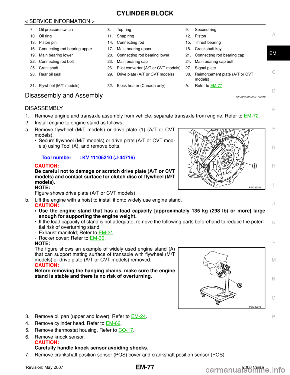
a. Remove flywheel (M/T models) or drive plate (1) (A/T or CVT
models).
• Secure flywheel (M/T models) or drive plate (A/T or CVT mod-
els) using Tool (A), and remove bolts.
CAUTION:
Be careful not to damage or scratch drive plate (A/T or CVT
models) and contact surface for clutch disc of flywheel (M/T
models).
NOTE:
Figure shows drive plate (A/T or CVT models)
b. Lift the engine with a hoist to install it onto widely use engine stand.
CAUTION:
• Use the engine stand that has a load capacity [approximately 135 kg (298 lb) or more] large
enough for supporting the engine weight.
• If the load capacity of stand is not adequate, remove the following parts beforehand to reduce the poten-
tial risk of overturning stand.
- Exhaust manifold; Refer to EM-21
.
- Rocker cover; Refer to EM-30
.
NOTE:
The figure shows an example of widely used engine stand (A)
that can support mating surface of transaxle with flywheel (M/T
models) or drive plate (A/T or CVT models) removed.
CAUTION:
Before removing the hanging chains, make sure the engine
stand is stable and there is no risk of overturning.
3. Remove oil pan (upper and lower). Refer to EM-24
.
4. Remove cylinder head. Refer to EM-62
.
5. Remove thermostat housing. Refer to CO-17
.
6. Remove knock sensor.
CAUTION:
Carefully handle knock sensor avoiding shocks.
7. Remove crankshaft position sensor (POS) cover and crankshaft position sensor (POS).
7. Oil pressure switch 8. Top ring 9. Second ring
10. Oil ring 11. Snap ring 12. Piston
13. Piston pin 14. Connecting rod 15. Thrust bearing
16. Connecting rod bearing upper 17. Main bearing upper 18. Crankshaft key
19. Main bearing lower 20. Connecting rod bearing lower 21. Connecting rod bearing cap
22. Connecting rod bolt 23. Main bearing cap 24. Main bearing cap bolt
25. Crankshaft 26. Pilot converter (A/T or CVT models) 27. Signal plate
28. Rear oil seal 29. Drive plate (A/T or CVT models) 30. Reinforcement plate (A/T or CVT
models)
31. Flywheel (M/T models) 32. Block heater (Canada only) A. Refer to EM-77
Tool number : KV 11105210 (J-44716)
PBIC3226J
PBIC3227J
Page 2256 of 2771
LU-6
< SERVICE INFORMATION >
ENGINE OIL
ENGINE OIL
InspectionINFOID:0000000001702518
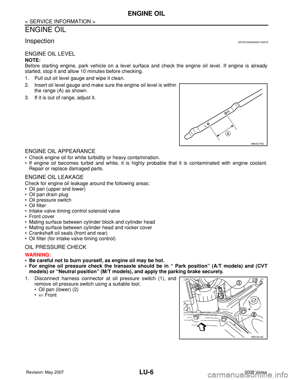
ENGINE OIL LEVEL
NOTE:
Before starting engine, park vehicle on a level surface and check the engine oil level. If engine is already
started, stop it and allow 10 minutes before checking.
1. Pull out oil level gauge and wipe it clean.
2. Insert oil level gauge and make sure the engine oil level is within
the range (A) as shown.
3. If it is out of range, adjust it.
ENGINE OIL APPEARANCE
• Check engine oil for white turbidity or heavy contamination.
• If engine oil becomes turbid and white, it is highly probable that it is contaminated with engine coolant.
Repair or replace damaged parts.
ENGINE OIL LEAKAGE
Check for engine oil leakage around the following areas:
• Oil pan (upper and lower)
• Oil pan drain plug
• Oil pressure switch
• Oil filter
• Intake valve timing control solenoid valve
• Front cover
• Mating surface between cylinder block and cylinder head
• Mating surface between cylinder head and rocker cover
• Crankshaft oil seals (front and rear)
• Oil filter (for intake valve timing control)
OIL PRESSURE CHECK
WARNING:
• Be careful not to burn yourself, as engine oil may be hot.
• For engine oil pressure check the transaxle should be in “ Park position” (A/T models) and (CVT
models) or “Neutral position” (M/T models), and apply the parking brake securely.
1. Disconnect harness connector at oil pressure switch (1), and
remove oil pressure switch using a suitable tool.
• Oil pan (lower) (2)
•⇐ Front
WBIA0776E
PBIC3310E