2008 NISSAN TIIDA P0720
[x] Cancel search: P0720Page 14 of 2771

AT-2
DTC Confirmation Procedure .................................86
Wiring Diagram - AT - PNP/SW ..............................87
Diagnosis Procedure ..............................................88
Component Inspection ............................................90
DTC P0710 A/T FLUID TEMPERATURE SEN-
SOR CIRCUIT ....................................................
91
Description ..............................................................91
CONSULT-III Reference Value in Data Monitor
Mode .......................................................................
91
On Board Diagnosis Logic ......................................91
Possible Cause .......................................................91
DTC Confirmation Procedure .................................91
Wiring Diagram - AT - FTS .....................................92
Diagnosis Procedure ..............................................92
Component Inspection ............................................95
DTC P0720 VEHICLE SPEED SENSOR A/T
(REVOLUTION SENSOR) .................................
96
Description ..............................................................96
CONSULT-III Reference Value in Data Monitor
Mode .......................................................................
96
On Board Diagnosis Logic ......................................96
Possible Cause .......................................................96
DTC Confirmation Procedure .................................96
Wiring Diagram - AT - VSSA/T ...............................97
Diagnosis Procedure ..............................................98
DTC P0725 ENGINE SPEED SIGNAL ............101
Description .............................................................101
CONSULT-III Reference Value in Data Monitor
Mode ......................................................................
101
On Board Diagnosis Logic .....................................101
Possible Cause ......................................................101
DTC Confirmation Procedure ................................101
Wiring Diagram - AT - ENGSS ..............................102
Diagnosis Procedure .............................................103
DTC P0731 A/T 1ST GEAR FUNCTION .........105
Description .............................................................105
On Board Diagnosis Logic .....................................105
Possible Cause ......................................................105
DTC Confirmation Procedure ................................105
Diagnosis Procedure .............................................106
DTC P0732 A/T 2ND GEAR FUNCTION .........108
Description .............................................................108
On Board Diagnosis Logic .....................................108
Possible Cause ......................................................108
DTC Confirmation Procedure ................................108
Diagnosis Procedure .............................................109
DTC P0733 A/T 3RD GEAR FUNCTION .........111
Description .............................................................111
On Board Diagnosis Logic .....................................111
Possible Cause ......................................................111
DTC Confirmation Procedure ................................111
Diagnosis Procedure .............................................112
DTC P0734 A/T 4TH GEAR FUNCTION .........114
Description ............................................................114
CONSULT-III Reference Value in Data Monitor
Mode .....................................................................
114
On Board Diagnosis Logic ....................................114
Possible Cause .....................................................114
DTC Confirmation Procedure ................................114
Diagnosis Procedure .............................................115
DTC P0740 TORQUE CONVERTER CLUTCH
SOLENOID VALVE ..........................................
119
Description ............................................................119
CONSULT-III Reference Value in Data Monitor
Mode .....................................................................
119
On Board Diagnosis Logic ....................................119
Possible Cause .....................................................119
DTC Confirmation Procedure ................................119
Wiring Diagram - AT - TCV ...................................120
Diagnosis Procedure .............................................121
Component Inspection ..........................................122
DTC P0744 A/T TCC S/V FUNCTION (LOCK-
UP) ....................................................................
124
Description ............................................................124
CONSULT-III Reference Value in Data Monitor
Mode .....................................................................
124
On Board Diagnosis Logic ....................................124
Possible Cause .....................................................124
DTC Confirmation Procedure ................................124
Diagnosis Procedure .............................................125
DTC P0745 LINE PRESSURE SOLENOID
VALVE ..............................................................
129
Description ............................................................129
CONSULT-III Reference Value in Data Monitor
Mode .....................................................................
129
On Board Diagnosis Logic ....................................129
Possible Cause .....................................................129
DTC Confirmation Procedure ................................129
Wiring Diagram - AT - LPSV .................................130
Diagnosis Procedure .............................................131
Component Inspection ..........................................133
DTC P0750 SHIFT SOLENOID VALVE A ........134
Description ............................................................134
CONSULT-III Reference Value in Data Monitor
Mode .....................................................................
134
On Board Diagnosis Logic ....................................134
Possible Cause .....................................................134
DTC Confirmation Procedure ................................134
Wiring Diagram - AT - SSV/A ................................135
Diagnosis Procedure .............................................136
Component Inspection ..........................................137
DTC P0755 SHIFT SOLENOID VALVE B ........139
Description ............................................................139
CONSULT-III Reference Value in Data Monitor
Mode .....................................................................
139
On Board Diagnosis Logic ....................................139
Possible Cause .....................................................139
DTC Confirmation Procedure ................................139
Page 17 of 2771
INDEX FOR DTC
AT-5
< SERVICE INFORMATION >
D
E
F
G
H
I
J
K
L
MA
B
AT
N
O
P
SERVICE INFORMATION
INDEX FOR DTC
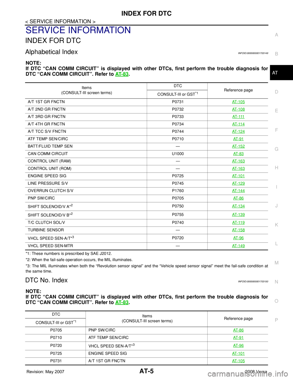
Alphabetical IndexINFOID:0000000001703149
NOTE:
If DTC “CAN COMM CIRCUIT” is displayed with other DTCs, first perform the trouble diagnosis for
DTC “CAN COMM CIRCUIT”. Refer to AT- 8 3
.
*1: These numbers is prescribed by SAE J2012.
*2: When the fail-safe operation occurs, the MIL illuminates.
*3: The MIL illuminates when both the “Revolution sensor signal” and the “Vehicle speed sensor signal” meet the fail-safe condition at
the same time.
DTC No. IndexINFOID:0000000001703150
NOTE:
If DTC “CAN COMM CIRCUIT” is displayed with other DTCs, first perform the trouble diagnosis for
DTC “CAN COMM CIRCUIT”. Refer to AT- 8 3
.
Items
(CONSULT-III screen terms)DTC
Reference page
CONSULT-III or GST
*1
A/T 1ST GR FNCTN P0731AT-105
A/T 2ND GR FNCTN P0732AT-108
A/T 3RD GR FNCTN P0733AT- 111
A/T 4TH GR FNCTN P0734AT- 11 4
A/T TCC S/V FNCTN P0744AT-124
ATF TEMP SEN/CIRC P0710AT- 9 1
BATT/FLUID TEMP SEN —AT-152
CAN COMM CIRCUIT U1000AT- 8 3
CONTROL UNIT (RAM) —AT-163
CONTROL UNIT (ROM) —AT-163
ENGINE SPEED SIG P0725AT-101
LINE PRESSURE S/V P0745AT-129
OVERRUN CLUTCH S/V P1760AT-144
PNP SW/CIRC P0705AT- 8 6
SHIFT SOLENOID/V A*2P0750AT-134
SHIFT SOLENOID/V B*2P0755AT-139
T/C CLUTCH SOL/V P0740AT- 11 9
TURBINE SENSOR —AT-158
VHCL SPEED SEN-A/T*3P0720AT- 9 6
VHCL SPEED SEN-MTR —AT-149
DTC
Items
(CONSULT-III screen terms) Reference page
CONSULT-III or GST
*1
P0705 PNP SW/CIRCAT- 8 6
P0710 ATF TEMP SEN/CIRCAT- 9 1
P0720
VHCL SPEED SEN-A/T*3AT- 9 6
P0725 ENGINE SPEED SIGAT- 1 0 1
P0731 A/T 1ST GR FNCTNAT- 1 0 5
Page 48 of 2771
AT-36
< SERVICE INFORMATION >
ON BOARD DIAGNOSTIC (OBD) SYSTEM
ON BOARD DIAGNOSTIC (OBD) SYSTEM
IntroductionINFOID:0000000001703172
A/T system has two self-diagnostic systems.
The first is emission-related on board diagnostic system (OBD-II) performed by the TCM in combination with
the ECM. The malfunction is indicated by the MIL (malfunction indicator lamp) and is stored as a DTC in the
ECM memory but not the TCM memory.
The second is the TCM original self-diagnosis indicated by the OD OFF indicator lamp. The malfunction is
stored in the TCM memory. The detected items are overlapped with OBD-II self-diagnostic items. For detail,
refer to AT-73, "
CONSULT-III Function (A/T)" .
OBD-II Function for A/T SystemINFOID:0000000001703173
The ECM provides emission-related on board diagnostic (OBD-II) functions for the A/T system. One function
is to receive a signal from the TCM used with OBD-related parts of the A/T system. The signal is sent to the
ECM when a malfunction occurs in the corresponding OBD-related part. The other function is to indicate a
diagnostic result by means of the MIL (malfunction indicator lamp) on the instrument panel. Sensors, switches
and solenoid valves are used as sensing elements.
The MIL automatically illuminates in One or Two Trip Detection Logic when a malfunction is sensed in relation
to A/T system parts.
One or Two Trip Detection Logic of OBD-IIINFOID:0000000001703174
ONE TRIP DETECTION LOGIC
If a malfunction is sensed during the first test drive, the MIL will illuminate and the malfunction will be stored in
the ECM memory as a DTC. The TCM is not provided with such a memory function.
TWO TRIP DETECTION LOGIC
When a malfunction is sensed during the first test drive, it is stored in the ECM memory as a 1st trip DTC
(diagnostic trouble code) or 1st trip freeze frame data. At this point, the MIL will not illuminate. — 1st trip
If the same malfunction as that experienced during the first test drive is sensed during the second test drive,
the MIL will illuminate. — 2nd trip
The “trip” in the “One or Two Trip Detection Logic” means a driving mode in which self-diagnosis is performed
during vehicle operation.
OBD-II Diagnostic Trouble Code (DTC)INFOID:0000000001703175
HOW TO READ DTC AND 1ST TRIP DTC
DTC and 1st trip DTC can be read by the following methods.
( with CONSULT-III or GST) CONSULT-III or GST (Generic Scan Tool) Examples: P0705, P0720 etc.
These DTC are prescribed by SAE J2012.
(CONSULT-III also displays the malfunctioning component or system.)
•1st trip DTC No. is the same as DTC No.
•Output of the diagnostic trouble code indicates that the indicated circuit has a malfunction. How-
ever, in case of the Mode II and GST, they do not indicate whether the malfunction is still occurring or
occurred in the past and returned to normal.
CONSULT-III can identify them as shown below, therefore, CONSULT-III (if available) is recom-
mended.
DTC or 1st trip DTC of a malfunction is displayed in SELF-DIAGNOSTIC RESULTS mode for “ENGINE” with
CONSULT-III. Time data indicates how many times the vehicle was driven after the last detection of a DTC.
If the DTC is being detected currently, the time data will be “0”.
If a 1st trip DTC is stored in the ECM, the time data will be “1t”.
Freeze Frame Data and 1st Trip Freeze Frame Data
The ECM has a memory function, which stores the driving condition such as fuel system status, calculated
load value, engine coolant temperature, short term fuel trim, long term fuel trim, engine speed and vehicle
speed at the moment the ECM detects a malfunction.
Page 87 of 2771
TROUBLE DIAGNOSIS
AT-75
< SERVICE INFORMATION >
D
E
F
G
H
I
J
K
L
MA
B
AT
N
O
P
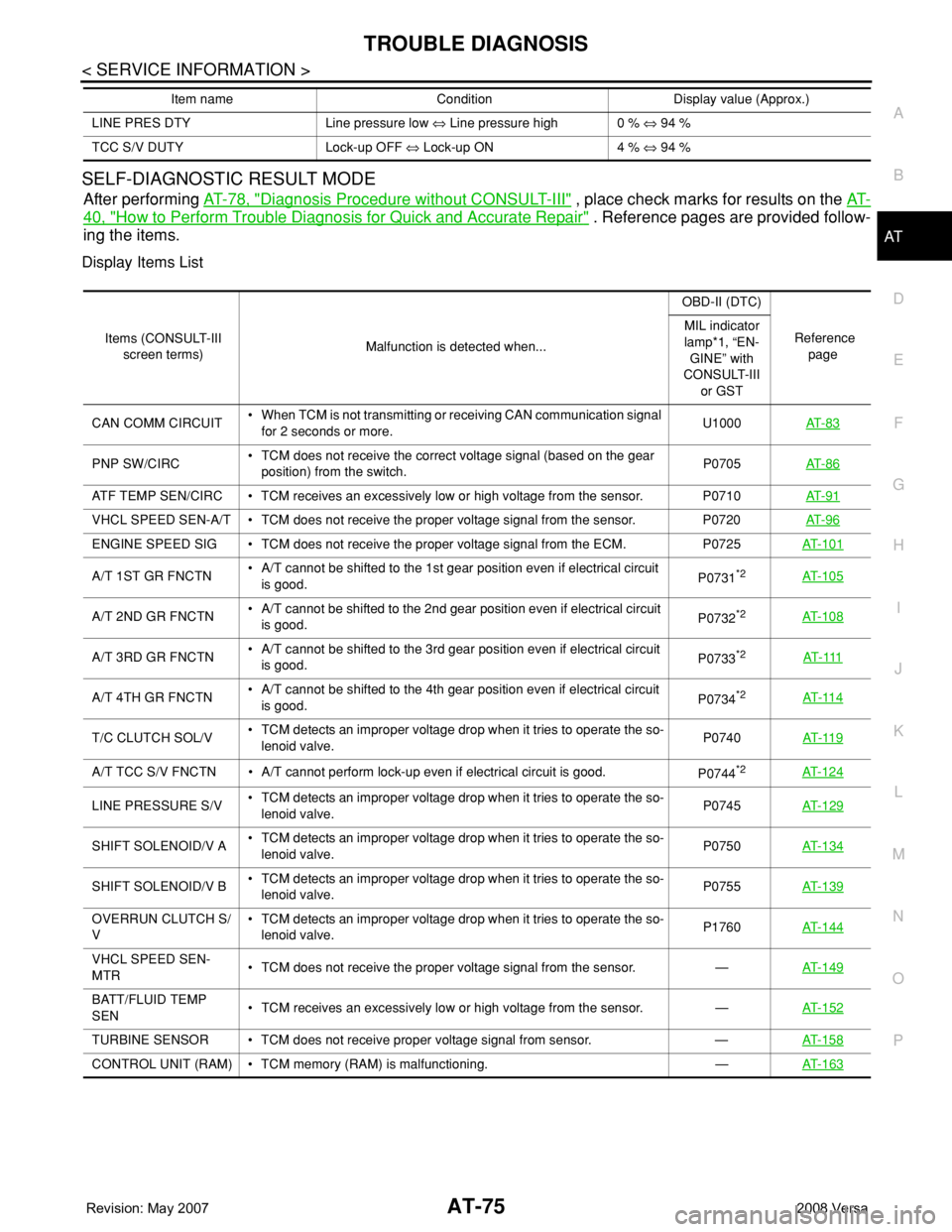
SELF-DIAGNOSTIC RESULT MODE
After performing AT-78, "Diagnosis Procedure without CONSULT-III" , place check marks for results on the AT-
40, "How to Perform Trouble Diagnosis for Quick and Accurate Repair" . Reference pages are provided follow-
ing the items.
Display Items List
LINE PRES DTY Line pressure low ⇔ Line pressure high 0 % ⇔ 94 %
TCC S/V DUTY Lock-up OFF ⇔ Lock-up ON 4 % ⇔ 94 % Item name Condition Display value (Approx.)
Items (CONSULT-III
screen terms)Malfunction is detected when...OBD-II (DTC)
Reference
page MIL indicator
lamp*1, “EN-
GINE” with
CONSULT-III
or GST
CAN COMM CIRCUIT• When TCM is not transmitting or receiving CAN communication signal
for 2 seconds or more.U1000AT- 8 3
PNP SW/CIRC• TCM does not receive the correct voltage signal (based on the gear
position) from the switch.P0705AT- 8 6
ATF TEMP SEN/CIRC • TCM receives an excessively low or high voltage from the sensor. P0710AT- 9 1
VHCL SPEED SEN-A/T • TCM does not receive the proper voltage signal from the sensor. P0720AT- 9 6
ENGINE SPEED SIG • TCM does not receive the proper voltage signal from the ECM. P0725AT- 1 0 1
A/T 1ST GR FNCTN• A/T cannot be shifted to the 1st gear position even if electrical circuit
is good.P0731*2AT- 1 0 5
A/T 2ND GR FNCTN• A/T cannot be shifted to the 2nd gear position even if electrical circuit
is good.P0732*2AT- 1 0 8
A/T 3RD GR FNCTN• A/T cannot be shifted to the 3rd gear position even if electrical circuit
is good.P0733*2AT- 111
A/T 4TH GR FNCTN• A/T cannot be shifted to the 4th gear position even if electrical circuit
is good.P0734*2AT- 11 4
T/C CLUTCH SOL/V• TCM detects an improper voltage drop when it tries to operate the so-
lenoid valve.P0740AT- 11 9
A/T TCC S/V FNCTN • A/T cannot perform lock-up even if electrical circuit is good.
P0744*2AT- 1 2 4
LINE PRESSURE S/V• TCM detects an improper voltage drop when it tries to operate the so-
lenoid valve.P0745AT- 1 2 9
SHIFT SOLENOID/V A• TCM detects an improper voltage drop when it tries to operate the so-
lenoid valve.P0750AT- 1 3 4
SHIFT SOLENOID/V B• TCM detects an improper voltage drop when it tries to operate the so-
lenoid valve.P0755 AT- 1 3 9
OVERRUN CLUTCH S/
V• TCM detects an improper voltage drop when it tries to operate the so-
lenoid valve.P1760AT- 1 4 4
VHCL SPEED SEN-
MTR• TCM does not receive the proper voltage signal from the sensor. —AT- 1 4 9
BATT/FLUID TEMP
SEN• TCM receives an excessively low or high voltage from the sensor. —AT- 1 5 2
TURBINE SENSOR • TCM does not receive proper voltage signal from sensor. —AT- 1 5 8
CONTROL UNIT (RAM) • TCM memory (RAM) is malfunctioning. —AT- 1 6 3
Page 108 of 2771
AT-96
< SERVICE INFORMATION >
DTC P0720 VEHICLE SPEED SENSOR A/T (REVOLUTION SENSOR)
DTC P0720 VEHICLE SPEED SENSOR A/T (REVOLUTION SENSOR)
DescriptionINFOID:0000000001703217
The revolution sensor detects the revolution of the idler gear parking pawl lock gear and emits a pulse signal.
The pulse signal is sent to the TCM which converts it into vehicle speed.
CONSULT-III Reference Value in Data Monitor ModeINFOID:0000000001703218
Remarks: Specification data are reference values.
On Board Diagnosis LogicINFOID:0000000001703219
• This is an OBD-II self-diagnostic item.
• Diagnostic trouble code “P0720 VHCL SPEED SEN-AT” with CONSULT-III or 1st judgement flicker without
CONSULT-III is detected when TCM does not receive the proper voltage signal from the sensor.
Possible CauseINFOID:0000000001703220
• Harness or connector
(The sensor circuit is open or shorted.)
• Revolution sensor
DTC Confirmation ProcedureINFOID:0000000001703221
CAUTION:
• Always drive vehicle at a safe speed.
• Be careful not to rev engine into the red zone on the tachometer.
• If performing this “DTC Confirmation Procedure” again, always turn ignition switch OFF and wait at
least 10 seconds before continuing.
After the repair, perform the following procedure to confirm the malfunction is eliminated.
WITH CONSULT-III
1. Turn ignition switch ON and select “DATA MONITOR” mode for “A/T” with CONSULT-III.
2. Touch “START”.
3. Drive vehicle and check for an increase of “VHCL/S SE-MTR” value.
If the check result is NG, go to AT-98, "
Diagnosis Procedure" .
If the check result is OK, go to following step.
4. Select “DATA MONITOR” mode for “A/T” with CONSULT-III.
5. Touch “START”.
6. Start engine and maintain the following conditions for at least 5 consecutive seconds.
VEHICLE SPEED: 30 km/h (19 MPH) or more
THROTTLE POSI: More than 1.0/8
SLCT LVR POSI: “D” position
Driving location: Driving the vehicle uphill (increased engine load) will help maintain the driving
conditions required for this test.
If the check result is NG, go to AT-98, "
Diagnosis Procedure" .
If the check result is OK, go to following step.
7. Maintain the following conditions for at least 5 consecutive seconds.
ENGINE SPEED: 3,500 rpm or more
THROTTLE POSI: More than 1.0/8
SLCT LVR POSI: “D” position
Driving location: Driving the vehicle uphill (increased engine load) will help maintain the driving
conditions required for this test.
WITH GST
Follow the procedure “WITH CONSULT-III”.
WITHOUT CONSULT-III
1. Start engine.
Item name Condition Display value
VHCL/S SE-A/T During driving Approximately matches the speedometer reading.
Page 109 of 2771
DTC P0720 VEHICLE SPEED SENSOR A/T (REVOLUTION SENSOR)
AT-97
< SERVICE INFORMATION >
D
E
F
G
H
I
J
K
L
MA
B
AT
N
O
P
2. Drive vehicle under the following conditions for more than 5 seconds.
Selector lever position: “D” position
Vehicle speed: 30 km/h (19 MPH) or more
Throttle position: greater than 1.0/8 of the full throttle position
3. Perform self-diagnosis. Refer to AT-78, "
Diagnosis Procedure without CONSULT-III" .
4. If the check result is NG, go to AT-98, "
Diagnosis Procedure" .
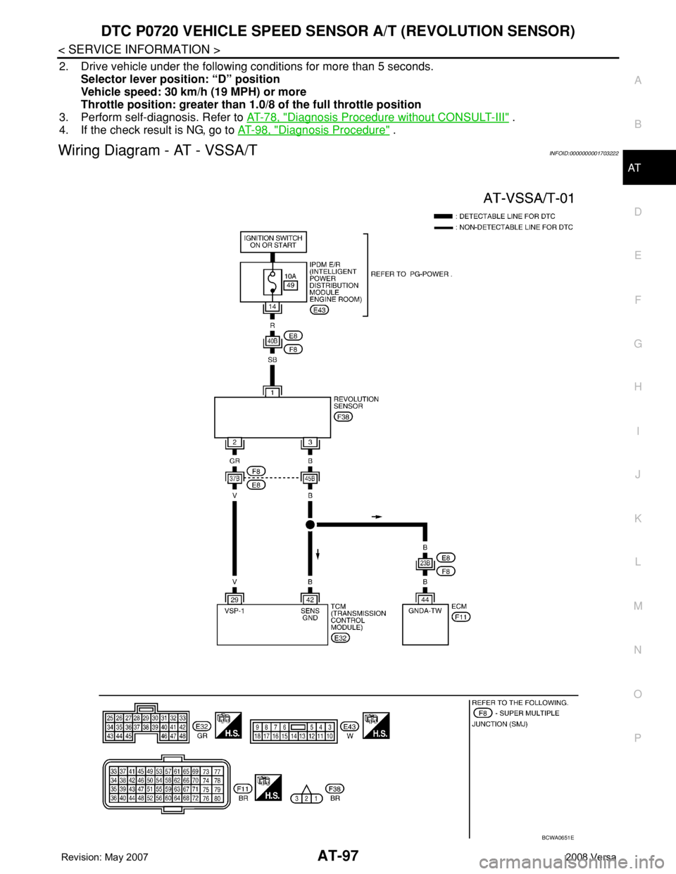
Wiring Diagram - AT - VSSA/TINFOID:0000000001703222
BCWA0651E
Page 110 of 2771
AT-98
< SERVICE INFORMATION >
DTC P0720 VEHICLE SPEED SENSOR A/T (REVOLUTION SENSOR)
TCM TERMINALS AND REFERENCE VALUES
Refer to AT-71, "TCM Terminal and Reference Value".
Diagnosis ProcedureINFOID:0000000001703223
1.CHECK INPUT SIGNAL
With CONSULT-III
1. Start engine.
2. Select “TCM INPUT SIGNALS” in “DATA MONITOR” mode for “A/T” with CONSULT-III.
3. Read out the value of “VHCL/S SE-A/T” while driving.
Check the value changes according to driving speed.
OK or NG
OK >> GO TO 8.
NG >> GO TO 2.
2. CHECK REVOLUTION SENSOR
With CONSULT-III
1. Start engine.
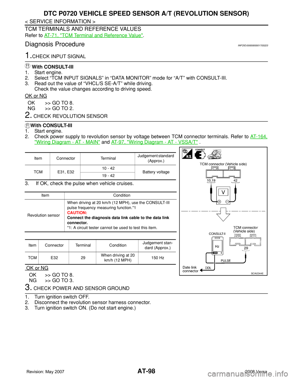
2. Check power supply to revolution sensor by voltage between TCM connector terminals. Refer to AT-164,
"Wiring Diagram - AT - MAIN" and AT-97, "Wiring Diagram - AT - VSSA/T" .
3. If OK, check the pulse when vehicle cruises.
OK or NG
OK >> GO TO 8.
NG >> GO TO 3.
3. CHECK POWER AND SENSOR GROUND
1. Turn ignition switch OFF.
2. Disconnect the revolution sensor harness connector.
3. Turn ignition switch ON. (Do not start engine.)
Item Connector TerminalJudgement standard
(Approx.)
TCM E31, E3210 - 42
Battery voltage
19 - 42
Item Condition
Revolution sensorWhen driving at 20 km/h (12 MPH), use the CONSULT-III
pulse frequency measuring function.*1
CAUTION:
Connect the diagnosis data link cable to the data link
connector.
*1: A circuit tester cannot be used to test this item.
Item Connector Terminal ConditionJudgement stan-
dard (Approx.)
TCM E32 29When driving at 20
km/h (12 MPH)150 Hz
SCIA2344E
Page 111 of 2771
DTC P0720 VEHICLE SPEED SENSOR A/T (REVOLUTION SENSOR)
AT-99
< SERVICE INFORMATION >
D
E
F
G
H
I
J
K
L
MA
B
AT
N
O
P
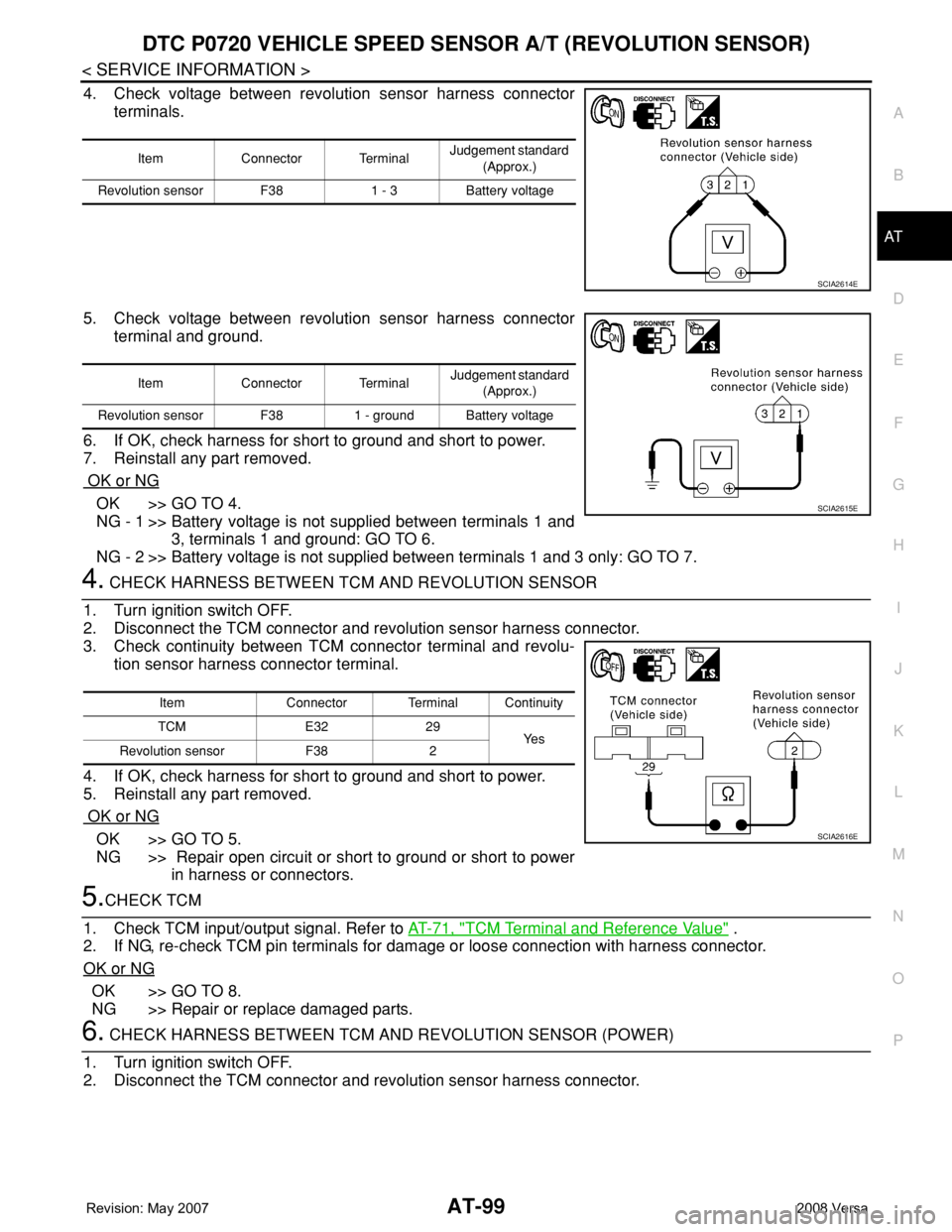
4. Check voltage between revolution sensor harness connector
terminals.
5. Check voltage between revolution sensor harness connector
terminal and ground.
6. If OK, check harness for short to ground and short to power.
7. Reinstall any part removed.
OK or NG
OK >> GO TO 4.
NG - 1 >> Battery voltage is not supplied between terminals 1 and
3, terminals 1 and ground: GO TO 6.
NG - 2 >> Battery voltage is not supplied between terminals 1 and 3 only: GO TO 7.
4. CHECK HARNESS BETWEEN TCM AND REVOLUTION SENSOR
1. Turn ignition switch OFF.
2. Disconnect the TCM connector and revolution sensor harness connector.
3. Check continuity between TCM connector terminal and revolu-
tion sensor harness connector terminal.
4. If OK, check harness for short to ground and short to power.
5. Reinstall any part removed.
OK or NG
OK >> GO TO 5.
NG >> Repair open circuit or short to ground or short to power
in harness or connectors.
5.CHECK TCM
1. Check TCM input/output signal. Refer to AT-71, "
TCM Terminal and Reference Value" .
2. If NG, re-check TCM pin terminals for damage or loose connection with harness connector.
OK or NG
OK >> GO TO 8.
NG >> Repair or replace damaged parts.
6. CHECK HARNESS BETWEEN TCM AND REVOLUTION SENSOR (POWER)
1. Turn ignition switch OFF.
2. Disconnect the TCM connector and revolution sensor harness connector.
Item Connector TerminalJudgement standard
(Approx.)
Revolution sensor F38 1 - 3 Battery voltage
SCIA2614E
Item Connector Terminal Judgement standard
(Approx.)
Revolution sensor F38 1 - ground Battery voltage
SCIA2615E
Item Connector Terminal Continuity
TCM E32 29
Ye s
Revolution sensor F38 2
SCIA2616E