2008 NISSAN TIIDA ignition coil
[x] Cancel search: ignition coilPage 381 of 2771
AV-22
< SERVICE INFORMATION >
AUDIO
Power Supply Circuit Inspection
INFOID:0000000001704663
1.CHECK FUSE
Check that the following fuses of the subwoofer (premium system) and audio unit are not blown.
OK or NG
OK >> GO TO 2.
NG >> If fuse is blown, be sure to eliminate cause of blown fuse before installing new fuse. Refer to PG-
3 .
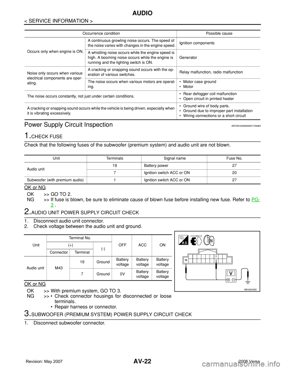
2.AUDIO UNIT POWER SUPPLY CIRCUIT CHECK
1. Disconnect audio unit connector.
2. Check voltage between the audio unit and ground.
OK or NG
OK >> With premium system, GO TO 3.
NG >> • Check connector housings for disconnected or loose
terminals.
• Repair harness or connector.
3.SUBWOOFER (PREMIUM SYSTEM) POWER SUPPLY CIRCUIT CHECK
1. Disconnect subwoofer connector.
Occurrence condition Possible cause
Occurs only when engine is ON.A continuous growling noise occurs. The speed of
the noise varies with changes in the engine speed.Ignition components
A whistling noise occurs while the engine speed is
high. A booming noise occurs while the engine is
running and the lighting switch is ON.Generator
Noise only occurs when various
electrical components are oper-
ating.A cracking or snapping sound occurs with the op-
eration of various switches.Relay malfunction, radio malfunction
The noise occurs when various motors are operat-
ing.• Motor case ground
• Motor
The noise occurs constantly, not just under certain conditions.• Rear defogger coil malfunction
• Open circuit in printed heater
A cracking or snapping sound occurs while the vehicle is being driven, especially when
it is vibrating excessively.• Ground wire of body parts.
• Ground due to improper part installation
• Wiring connections or a short circuit
Unit Terminals Signal name Fuse No.
Audio unit19 Battery power 27
7 Ignition switch ACC or ON 20
Subwoofer (with premium audio) 1 Ignition switch ACC or ON 27
UnitTe r m i n a l N o .
OFF ACC ON (+)
(-)
Connector Terminal
Audio unit M4319 GroundBattery
voltageBattery
voltageBattery
voltage
7Ground0VBattery
voltageBattery
voltage
WKIA5345E
Page 976 of 2771
DTC P1777 STEP MOTOR - CIRCUIT
CVT-137
< SERVICE INFORMATION >
D
E
F
G
H
I
J
K
L
MA
B
CVT
N
O
P
DTC P1777 STEP MOTOR - CIRCUIT
DescriptionINFOID:0000000001703640
• The step motor is included in the control valve assembly.
• The step motor changes the step with turning 4 coils ON/OFF according to the signal from TCM. As a result,
the flow of line pressure to primary pulley is changed and pulley ratio is controlled
CONSULT-III Reference Value in Data Monitor ModeINFOID:0000000001703641
Remarks: Specification data are reference values.
On Board Diagnosis LogicINFOID:0000000001703642
• This is an OBD-II self-diagnostic item.
• Diagnostic trouble code “P1777 STEP MOTR CIRC” with CONSULT-III is detected under the following con-
ditions.
- When operating step motor ON and OFF, there is no proper change in the voltage of TCM terminal which
corresponds to it.
Possible CauseINFOID:0000000001703643
• Step motor
• Harness or connectors
(Step motor circuit is open or shorted.)
DTC Confirmation ProcedureINFOID:0000000001703644
CAUTION:
Always drive vehicle at a safe speed.
NOTE:
If “DTC Confirmation Procedure” has been previously performed, always turn ignition switch OFF and
wait at least 10 seconds before performing the next test.
After the repair, touch “ERASE” on “SELF-DIAG RESULTS” and then perform the following procedure to con-
firm the malfunction is eliminated.
WITH CONSULT-III
1. Turn ignition switch ON and select “DATA MONITOR” mode for “TRANSMISSION” with CONSULT-III.
2. Drive vehicle for at least 5 consecutive seconds.
3. If DTC is detected, go to CVT-139, "
Diagnosis Procedure" .
WITH GST
Follow the procedure “WITH CONSULT-III”.
Item name Condition Display value (Approx.)
STM STEP
During driving−20 step - 180 step
SMCOIL A
Changes ON⇔OFF. SMCOIL B
SMCOIL C
SMCOIL D
Page 978 of 2771
DTC P1777 STEP MOTOR - CIRCUIT
CVT-139
< SERVICE INFORMATION >
D
E
F
G
H
I
J
K
L
MA
B
CVT
N
O
P
Diagnosis ProcedureINFOID:0000000001703646
1.CHECK INPUT SIGNALS
With CONSULT-III
1. Start engine.
2. Select “SELECTION FROM MENU” in “DATA MONITOR” mode for “TRANSMISSION” with CONSULT-III.
3. Start vehicle and read out the value of “STM STEP”, “SMCOIL A”, “SMCOIL B”, “SMCOIL C”, and
“SMCOIL D”.
OK or NG
OK >> GO TO 4.
NG >> GO TO 2.
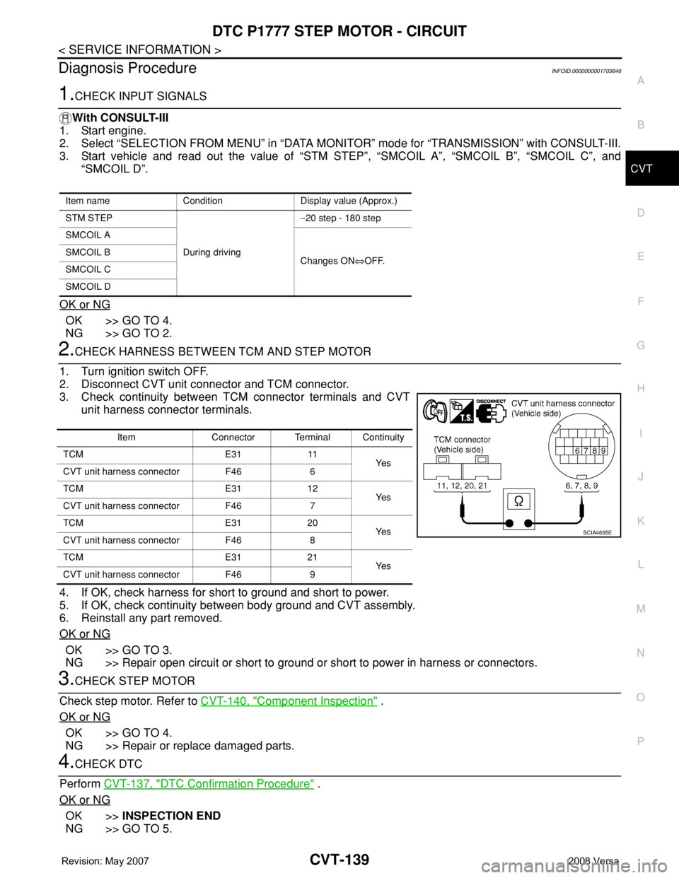
2.CHECK HARNESS BETWEEN TCM AND STEP MOTOR
1. Turn ignition switch OFF.
2. Disconnect CVT unit connector and TCM connector.
3. Check continuity between TCM connector terminals and CVT
unit harness connector terminals.
4. If OK, check harness for short to ground and short to power.
5. If OK, check continuity between body ground and CVT assembly.
6. Reinstall any part removed.
OK or NG
OK >> GO TO 3.
NG >> Repair open circuit or short to ground or short to power in harness or connectors.
3.CHECK STEP MOTOR
Check step motor. Refer to CVT-140, "
Component Inspection" .
OK or NG
OK >> GO TO 4.
NG >> Repair or replace damaged parts.
4.CHECK DTC
Perform CVT-137, "
DTC Confirmation Procedure" .
OK or NG
OK >>INSPECTION END
NG >> GO TO 5.
Item name Condition Display value (Approx.)
STM STEP
During driving−20 step - 180 step
SMCOIL A
Changes ON⇔OFF. SMCOIL B
SMCOIL C
SMCOIL D
Item Connector Terminal Continuity
TCM E31 11
Ye s
CVT unit harness connector F46 6
TCM E31 12
Ye s
CVT unit harness connector F46 7
TCM E31 20
Ye s
CVT unit harness connector F46 8
TCM E31 21
Ye s
CVT unit harness connector F46 9
SCIA4695E
Page 1091 of 2771
PRECAUTIONS
EC-17
< SERVICE INFORMATION >
C
D
E
F
G
H
I
J
K
L
MA
EC
N
P O
PrecautionINFOID:0000000001702551
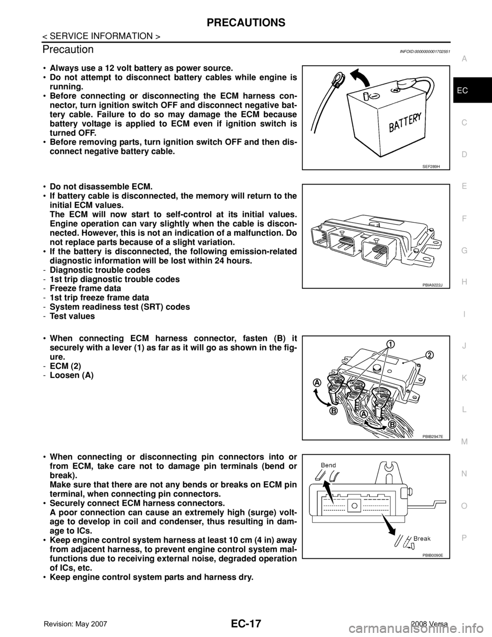
•Always use a 12 volt battery as power source.
•Do not attempt to disconnect battery cables while engine is
running.
•Before connecting or disconnecting the ECM harness con-
nector, turn ignition switch OFF and disconnect negative bat-
tery cable. Failure to do so may damage the ECM because
battery voltage is applied to ECM even if ignition switch is
turned OFF.
•Before removing parts, turn ignition switch OFF and then dis-
connect negative battery cable.
•Do not disassemble ECM.
•If battery cable is disconnected, the memory will return to the
initial ECM values.
The ECM will now start to self-control at its initial values.
Engine operation can vary slightly when the cable is discon-
nected. However, this is not an indication of a malfunction. Do
not replace parts because of a slight variation.
•If the battery is disconnected, the following emission-related
diagnostic information will be lost within 24 hours.
-Diagnostic trouble codes
-1st trip diagnostic trouble codes
-Freeze frame data
-1st trip freeze frame data
-System readiness test (SRT) codes
-Test values
•When connecting ECM harness connector, fasten (B) it
securely with a lever (1) as far as it will go as shown in the fig-
ure.
-ECM (2)
-Loosen (A)
•When connecting or disconnecting pin connectors into or
from ECM, take care not to damage pin terminals (bend or
break).
Make sure that there are not any bends or breaks on ECM pin
terminal, when connecting pin connectors.
•Securely connect ECM harness connectors.
A poor connection can cause an extremely high (surge) volt-
age to develop in coil and condenser, thus resulting in dam-
age to ICs.
•Keep engine control system harness at least 10 cm (4 in) away
from adjacent harness, to prevent engine control system mal-
functions due to receiving external noise, degraded operation
of ICs, etc.
•Keep engine control system parts and harness dry.
SEF289H
PBIA9222J
PBIB2947E
PBIB0090E
Page 1148 of 2771
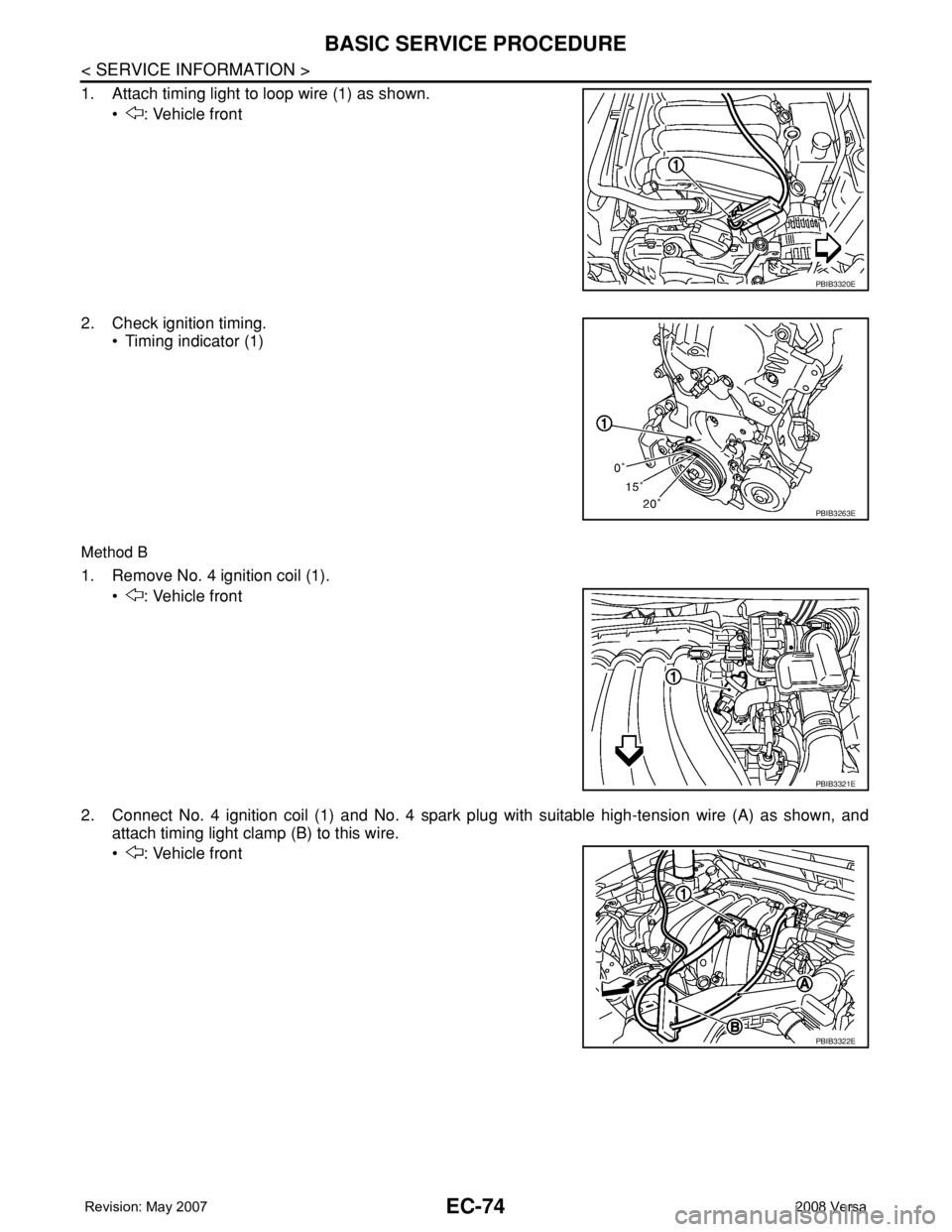
EC-74
< SERVICE INFORMATION >
BASIC SERVICE PROCEDURE
1. Attach timing light to loop wire (1) as shown.
• : Vehicle front
2. Check ignition timing.
• Timing indicator (1)
Method B
1. Remove No. 4 ignition coil (1).
• : Vehicle front
2. Connect No. 4 ignition coil (1) and No. 4 spark plug with suitable high-tension wire (A) as shown, and
attach timing light clamp (B) to this wire.
• : Vehicle front
PBIB3320E
PBIB3263E
PBIB3321E
PBIB3322E
Page 1167 of 2771
TROUBLE DIAGNOSIS
EC-93
< SERVICE INFORMATION >
C
D
E
F
G
H
I
J
K
L
MA
EC
N
P O
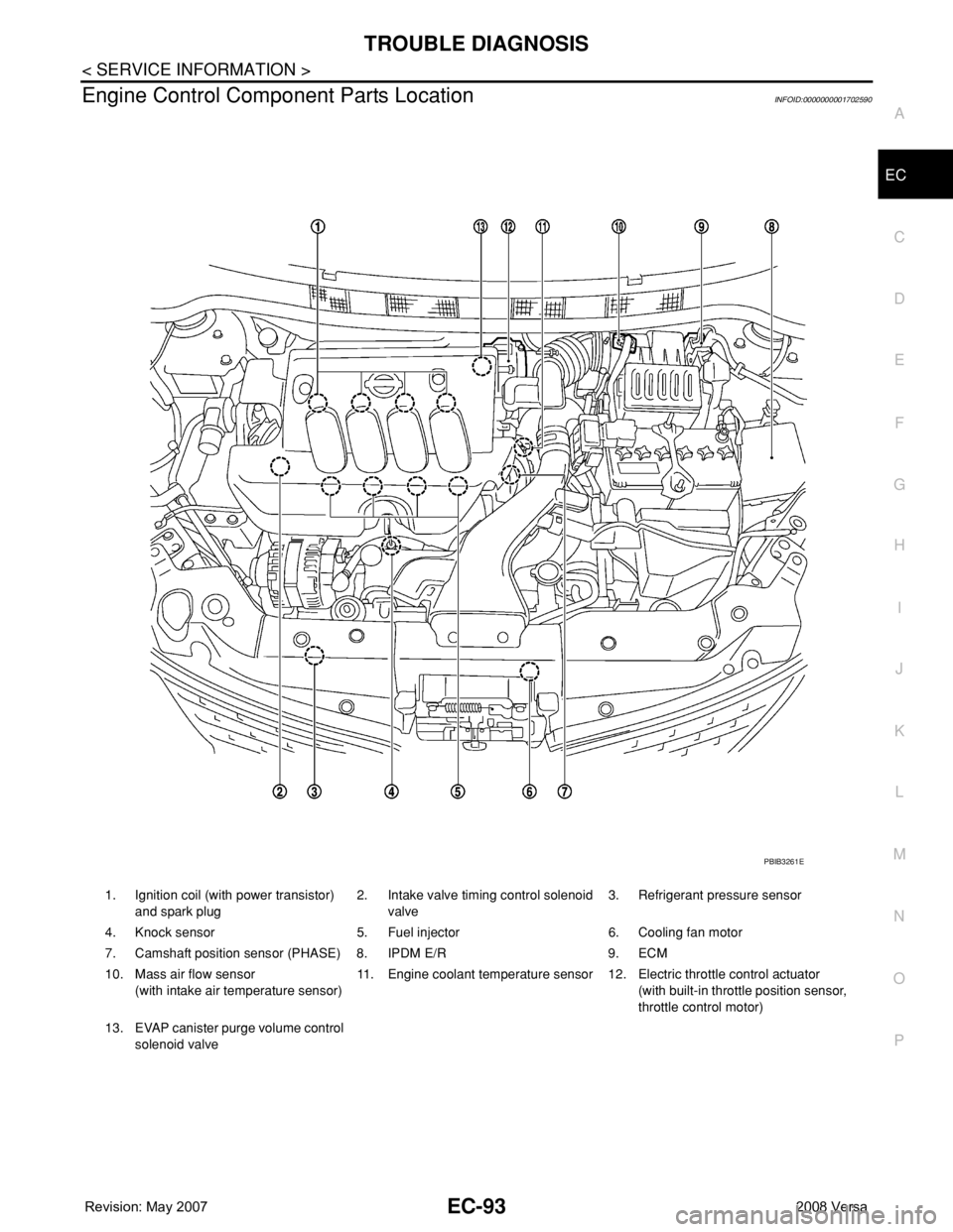
Engine Control Component Parts LocationINFOID:0000000001702590
1. Ignition coil (with power transistor)
and spark plug2. Intake valve timing control solenoid
valve3. Refrigerant pressure sensor
4. Knock sensor 5. Fuel injector 6. Cooling fan motor
7. Camshaft position sensor (PHASE) 8. IPDM E/R 9. ECM
10. Mass air flow sensor
(with intake air temperature sensor)11. Engine coolant temperature sensor 12. Electric throttle control actuator
(with built-in throttle position sensor,
throttle control motor)
13. EVAP canister purge volume control
solenoid valve
PBIB3261E
Page 1169 of 2771
TROUBLE DIAGNOSIS
EC-95
< SERVICE INFORMATION >
C
D
E
F
G
H
I
J
K
L
MA
EC
N
P O
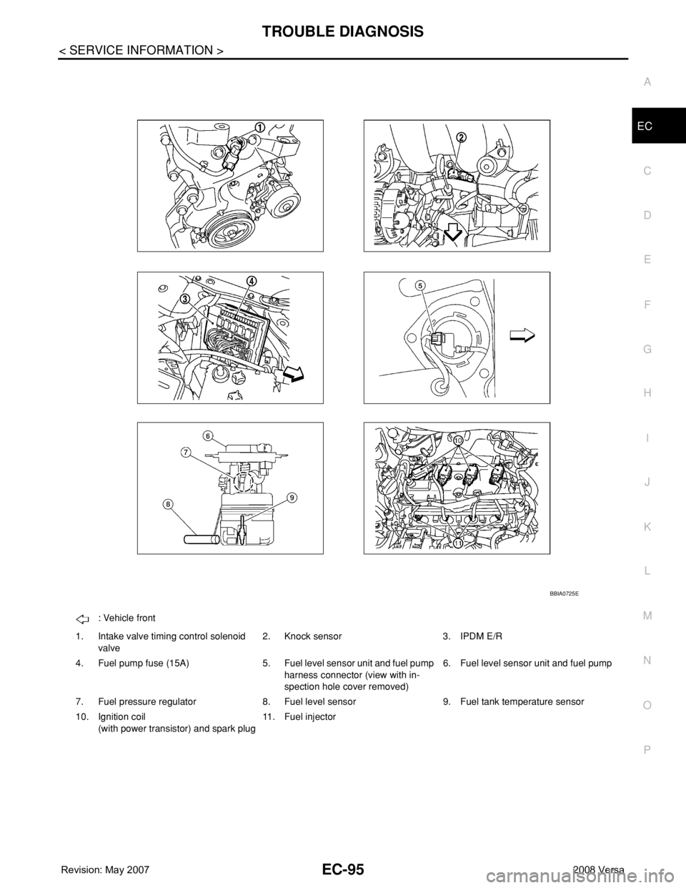
: Vehicle front
1. Intake valve timing control solenoid
valve2. Knock sensor 3. IPDM E/R
4. Fuel pump fuse (15A) 5. Fuel level sensor unit and fuel pump
harness connector (view with in-
spection hole cover removed)6. Fuel level sensor unit and fuel pump
7. Fuel pressure regulator 8. Fuel level sensor 9. Fuel tank temperature sensor
10. Ignition coil
(with power transistor) and spark plug11. Fuel injector
BBIA0725E
Page 1191 of 2771

TROUBLE DIAGNOSIS
EC-117
< SERVICE INFORMATION >
C
D
E
F
G
H
I
J
K
L
MA
EC
N
P O
NOTE:
Any monitored item that does not match the vehicle being diagnosed is deleted from the display automatically.
ACTIVE TEST MODE
Test Item
Monitored item [Unit]ECM
input
signalsMain
signalsDescription Remarks
ENG SPEED [rpm]×ו Indicates the engine speed computed
from the signal of the crankshaft position
sensor (POS) and camshaft position
sensor (PHASE).
MAS A/F SE-B1 [V]×ו The signal voltage of the mass air flow
sensor specification is displayed.• When engine is running specification
range is indicated.
B/FUEL SCHDL
[msec]ו “Base fuel schedule” indicates the fuel in-
jection pulse width programmed into
ECM, prior to any learned on board cor-
rection.• When engine is running specification
range is indicated.
A/F ALPHA-B1 [%]ו The mean value of the air-fuel ratio feed-
back correction factor per cycle is indi-
cated.• When engine is running specification
range is indicated.
• This data also includes the data for the
air-fuel ratio learning control.
TEST ITEM CONDITION JUDGEMENT CHECK ITEM (REMEDY)
FUEL INJEC-
TION• Engine: Return to the original
trouble condition
• Change the amount of fuel injec-
tion using CONSULT-II.If trouble symptom disappears, see
CHECK ITEM.• Harness and connectors
• Fuel injector
• Air fuel ratio (A/F) sensor 1
IGNITION TIM-
ING• Engine: Return to the original
trouble condition
• Timing light: Set
• Retard the ignition timing using
CONSULT-II.If trouble symptom disappears, see
CHECK ITEM.• Perform Idle Air Volume Learning.
POWER BAL-
ANCE• Engine: After warming up, idle the
engine.
• A/C switch OFF
• Shift lever: P or N (A/T, CVT),
Neutral (M/T)
• Cut off each fuel injector signal
one at a time using CONSULT-II.Engine runs rough or dies.• Harness and connectors
• Compression
• Fuel injector
• Power transistor
•Spark plug
• Ignition coil
COOLING FAN*• Ignition switch: ON
• Turn the cooling fan “LOW”, “HI”
and “OFF” with CONSULT-II.Cooling fan moves and stops.• Harness and connectors
• Cooling fan relay
• Cooling fan motor
ENG COOLANT
TEMP• Engine: Return to the original
trouble condition
• Change the engine coolant tem-
perature using CONSULT-II.If trouble symptom disappears, see
CHECK ITEM.• Harness and connectors
• Engine coolant temperature sen-
sor
• Fuel injector
FUEL PUMP RE-
LAY• Ignition switch: ON
(Engine stopped)
• Turn the fuel pump relay ON and
OFF using CONSULT-II and lis-
ten to operating sound.Fuel pump relay makes the operat-
ing sound.• Harness and connectors
• Fuel pump relay
PURG VOL
CONT/V• Engine: After warming up, run en-
gine at 1,500 rpm.
• Change the EVAP canister purge
volume control solenoid valve
opening percent using CON-
SULT-II.Engine speed changes according to
the opening percent.• Harness and connectors
• EVAP canister purge volume con-
trol solenoid valve