2008 NISSAN TIIDA air cleaner assembly removal
[x] Cancel search: air cleaner assembly removalPage 744 of 2771
BRAKE MASTER CYLINDER
BR-13
< SERVICE INFORMATION >
C
D
E
G
H
I
J
K
L
MA
B
BR
N
O
P
BRAKE MASTER CYLINDER
On-Board InspectionINFOID:0000000001703788
LEAK INSPECTION
• Check for leaking in a master cylinder installation surface, a reservoir tank installation surface, and brake
tube connections.
Removal and InstallationINFOID:0000000001703789
CAUTION:
Be careful not to splash brake fluid on painted areas; it may cause paint damage. If brake fluid is
splashed on painted areas, immediately wipe them with cloth and wash it away with water.
REMOVAL
1. Drain brake fluid. Refer to BR-8, "Drain and Refill" .
2. Remove battery. Refer to SC-6, "
Removal and Installation" .
3. Remove air duct. Refer to EM-16, "
Removal and Installation" .
4. Remove air cleaner. Refer to EM-16, "
Removal and Installation" .
5. Disconnect brake fluid level switch harness connector.
6. Using a flare nut wrench, remove brake tube from master cylinder.
7. Remove master cylinder assembly nuts, and remove master cylinder assembly from vehicle..
INSTALLATION
CAUTION:
• Refill using recommended brake fluid. Refer to MA-10
.
• Never reuse drained brake fluid.
• Check if the rod of primary piston has dust or scratches.
1. Install master cylinder to brake booster assembly, and tighten nuts to the specified torque. Refer to BR-18,
"Removal and Installation".
CAUTION:
• Do not damage or strain rod of primary piston.
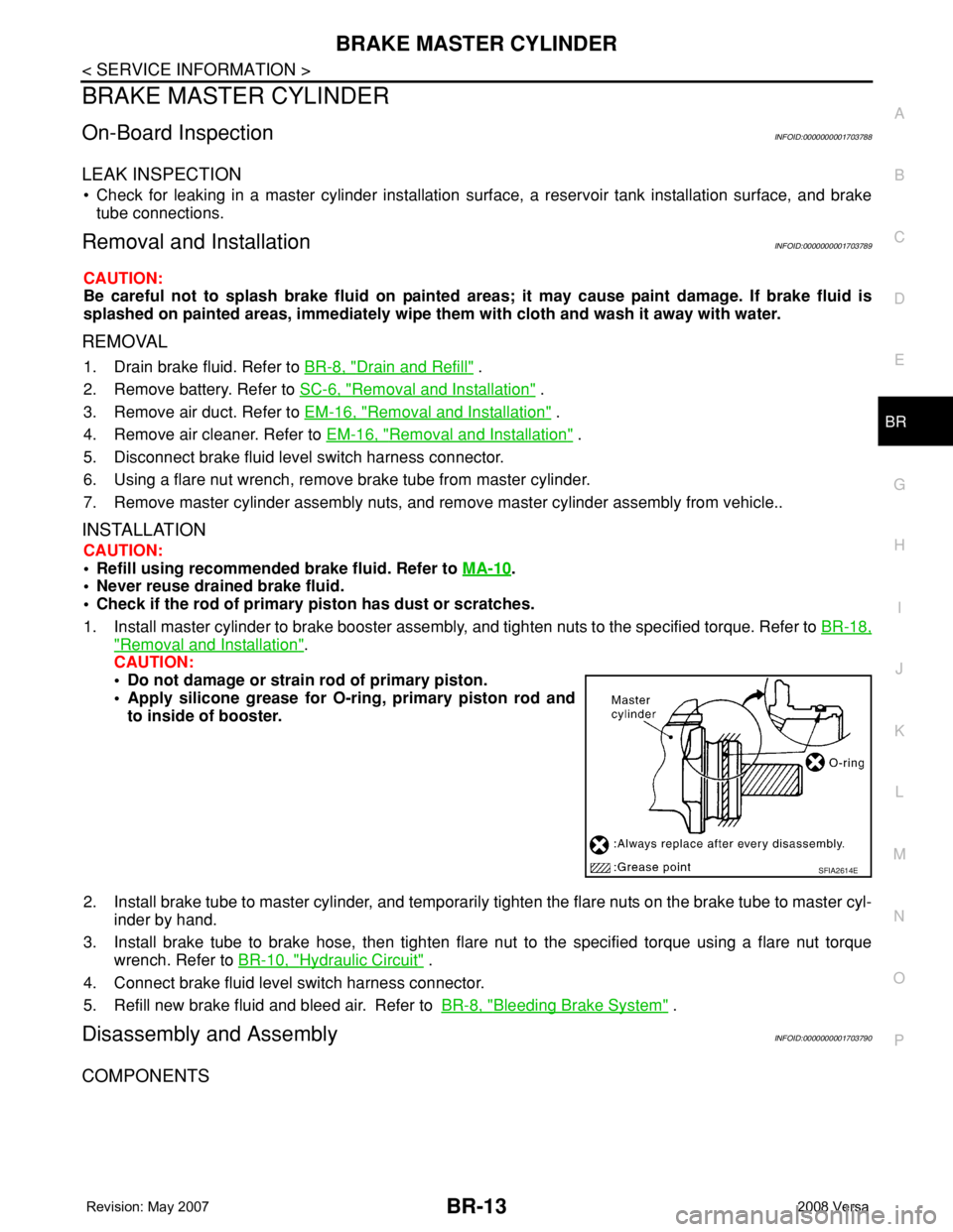
• Apply silicone grease for O-ring, primary piston rod and
to inside of booster.
2. Install brake tube to master cylinder, and temporarily tighten the flare nuts on the brake tube to master cyl-
inder by hand.
3. Install brake tube to brake hose, then tighten flare nut to the specified torque using a flare nut torque
wrench. Refer to BR-10, "
Hydraulic Circuit" .
4. Connect brake fluid level switch harness connector.
5. Refill new brake fluid and bleed air. Refer toBR-8, "
Bleeding Brake System" .
Disassembly and AssemblyINFOID:0000000001703790
COMPONENTS
SFIA2614E
Page 810 of 2771
CLUTCH MASTER CYLINDER
CL-9
< SERVICE INFORMATION >
D
E
F
G
H
I
J
K
L
MA
B
CL
N
O
P
CLUTCH MASTER CYLINDER
Removal and InstallationINFOID:0000000001703120
REMOVAL
1. Remove the battery, battery tray and brackets. Refer to SC-4.
2. Remove the air cleaner and air duct. Refer to EM-16
.
3. Use one of the following methods to remove hose from master cylinder.
• Drain clutch fluid from reservoir tank and remove hose.
• Remove hose from master cylinder. Immediately plug hose and reservoir tank to prevent clutch fluid
from dripping.
CAUTION:
Do not spill clutch fluid onto painted surfaces. If it spills, wipe up immediately and wash the
affected area with water.
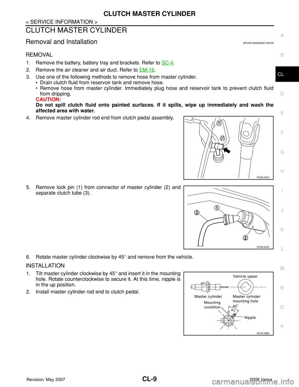
4. Remove master cylinder rod end from clutch pedal assembly.
5. Remove lock pin (1) from connector of master cylinder (2) and
separate clutch tube (3).
6. Rotate master cylinder clockwise by 45° and remove from the vehicle.
INSTALLATION
1. Tilt master cylinder clockwise by 45° and insert it in the mounting
hole. Rotate counterclockwise to secure it. At this time, nipple is
in the up position.
2. Install master cylinder rod end to clutch pedal.
PCIB1491E
PCIB1497E
SCIA1286E
Page 1678 of 2771
EM-1
ENGINE
C
D
E
F
G
H
I
J
K
L
M
SECTION EM
A
EM
N
O
P
CONTENTS
ENGINE MECHANICAL
SERVICE INFORMATION ............................3
PRECAUTIONS ...................................................3
Precaution for Supplemental Restraint System
(SRS) "AIR BAG" and "SEAT BELT PRE-TEN-
SIONER" ...................................................................
3
Precaution for Procedure without Cowl Top Cover ......3
Precaution Necessary for Steering Wheel Rota-
tion After Battery Disconnect .....................................
3
Precaution for Drain Coolant .....................................4
Precaution for Disconnecting Fuel Piping .................4
Precaution for Removal and Disassembly ................4
Precaution for Inspection, Repair and Replace-
ment ..........................................................................
4
Precaution for Assembly and Installation ..................4
Parts Requiring Angular Tightening ..........................4
Precaution for Liquid Gasket .....................................5
PREPARATION ...................................................7
Special Service Tool .................................................7
Commercial Service Tool ..........................................9
NOISE, VIBRATION AND HARSHNESS
(NVH) TROUBLESHOOTING ............................
11
NVH Troubleshooting - Engine Noise .....................11
Use the Chart Below to Help You Find the Cause
of the Symptom .......................................................
12
DRIVE BELTS ....................................................13
Component ..............................................................13
Checking Drive Belts ...............................................13
Tension Adjustment ................................................13
Removal and Installation .........................................13
Component ..............................................................14
Removal and Installation of Drive Belt Auto Ten-
sioner ......................................................................
14
AIR CLEANER AND AIR DUCT ........................16
Component ..............................................................16
Removal and Installation .........................................16
Changing Air Cleaner Filter .....................................17
INTAKE MANIFOLD .........................................18
Component ..............................................................18
Removal and Installation .........................................18
EXHAUST MANIFOLD ......................................21
Component ..............................................................21
Removal and Installation .........................................21
OIL PAN ............................................................24
Component ..............................................................24
Removal and Installation .........................................24
IGNITION COIL, SPARK PLUG AND ROCK-
ER COVER ........................................................
30
Component ..............................................................30
Removal and Installation .........................................30
FUEL INJECTOR AND FUEL TUBE ................33
Component ..............................................................33
Removal and Installation .........................................33
TIMING CHAIN ..................................................37
Component ..............................................................37
Removal and Installation .........................................38
CAMSHAFT .......................................................47
Component ..............................................................47
Removal and Installation .........................................47
Valve Clearance ......................................................55
OIL SEAL ..........................................................59
Removal and Installation of Valve Oil Seal ..............59
Removal and Installation of Front Oil Seal ..............59
Removal and Installation of Rear Oil Seal ...............60
CYLINDER HEAD .............................................62
On-Vehicle Service ..................................................62
Component ..............................................................63
Removal and Installation .........................................63
Component ..............................................................65
Disassembly and Assembly .....................................66
Inspection After Disassembly ..................................67
Page 1694 of 2771
AIR CLEANER AND AIR DUCT
EM-17
< SERVICE INFORMATION >
C
D
E
F
G
H
I
J
K
L
MA
EM
N
P O
• Align marks.
• Attach each joint securely.
• Screw clamps firmly.
Changing Air Cleaner FilterINFOID:0000000001702482
REMOVAL
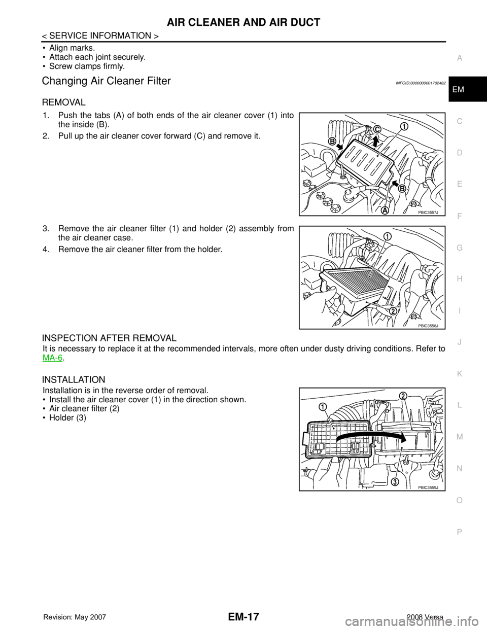
1. Push the tabs (A) of both ends of the air cleaner cover (1) into
the inside (B).
2. Pull up the air cleaner cover forward (C) and remove it.
3. Remove the air cleaner filter (1) and holder (2) assembly from
the air cleaner case.
4. Remove the air cleaner filter from the holder.
INSPECTION AFTER REMOVAL
It is necessary to replace it at the recommended intervals, more often under dusty driving conditions. Refer to
MA-6
.
INSTALLATION
Installation is in the reverse order of removal.
• Install the air cleaner cover (1) in the direction shown.
• Air cleaner filter (2)
• Holder (3)
PBIC3557J
PBIC3558J
PBIC3559J
Page 1750 of 2771
ENGINE ASSEMBLY
EM-73
< SERVICE INFORMATION >
C
D
E
F
G
H
I
J
K
L
MA
EM
N
P O
• Use either 2-pole lift type or separate type lift as best you can. If board-on type is used for unavoid-
able reasons, support at the rear axle jacking point with a transmission jack or similar tool before
starting work, in preparation for the backward shift of center of gravity.
• For supporting points for lifting and jacking point at rear axle, refer to GI-38, "
Garage Jack and
Safety Stand and 2-Pole Lift".
REMOVAL
Remove the engine and the transaxle assembly from the vehicle downward. Separate the engine and the tran-
saxle.
1. Remove engine undercover
2. Drain engine coolant from radiator. Refer to CO-8, "
Changing Engine Coolant".
CAUTION:
• Perform this step when the engine is cold.
• Do not spill engine coolant on drive belt.
3. Remove front fender protector (RH and LH); Refer to EI-23
.
4. Remove exhaust front tube; Refer to EX-4
.
5. Remove drive shafts (LH and RH) from steering knuckle. Refer to FAX-8
.
6. Remove transaxle joint bolts which pierce at oil pan (upper) lower rear side. Refer to AT-226
(A/T models),
CVT-178
(CVT) or MT-16 (M/T models).
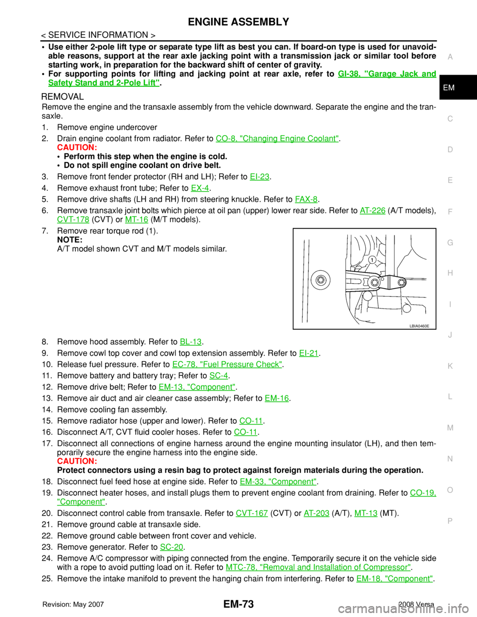
7. Remove rear torque rod (1).
NOTE:
A/T model shown CVT and M/T models similar.
8. Remove hood assembly. Refer to BL-13
.
9. Remove cowl top cover and cowl top extension assembly. Refer to EI-21
.
10. Release fuel pressure. Refer to EC-78, "
Fuel Pressure Check".
11. Remove battery and battery tray; Refer to SC-4
.
12. Remove drive belt; Refer to EM-13, "
Component".
13. Remove air duct and air cleaner case assembly; Refer to EM-16
.
14. Remove cooling fan assembly.
15. Remove radiator hose (upper and lower). Refer to CO-11
.
16. Disconnect A/T, CVT fluid cooler hoses. Refer to CO-11
.
17. Disconnect all connections of engine harness around the engine mounting insulator (LH), and then tem-
porarily secure the engine harness into the engine side.
CAUTION:
Protect connectors using a resin bag to protect against foreign materials during the operation.
18. Disconnect fuel feed hose at engine side. Refer to EM-33, "
Component".
19. Disconnect heater hoses, and install plugs them to prevent engine coolant from draining. Refer to CO-19,
"Component".
20. Disconnect control cable from transaxle. Refer to CVT-167
(CVT) or AT-203 (A/T), MT-13 (MT).
21. Remove ground cable at transaxle side.
22. Remove ground cable between front cover and vehicle.
23. Remove generator. Refer to SC-20
.
24. Remove A/C compressor with piping connected from the engine. Temporarily secure it on the vehicle side
with a rope to avoid putting load on it. Refer to MTC-78, "
Removal and Installation of Compressor".
25. Remove the intake manifold to prevent the hanging chain from interfering. Refer to EM-18, "
Component".
LBIA0460E
Page 2275 of 2771
ENGINE MAINTENANCE
MA-15
< SERVICE INFORMATION >
C
D
E
F
G
H
I
J
K
MA
B
MA
N
O
P
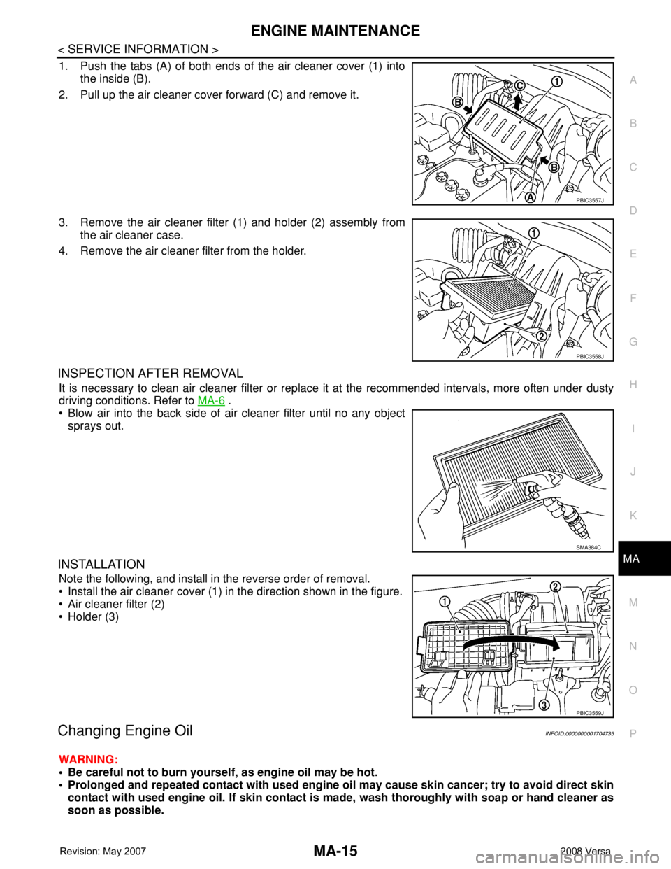
1. Push the tabs (A) of both ends of the air cleaner cover (1) into
the inside (B).
2. Pull up the air cleaner cover forward (C) and remove it.
3. Remove the air cleaner filter (1) and holder (2) assembly from
the air cleaner case.
4. Remove the air cleaner filter from the holder.
INSPECTION AFTER REMOVAL
It is necessary to clean air cleaner filter or replace it at the recommended intervals, more often under dusty
driving conditions. Refer to MA-6
.
• Blow air into the back side of air cleaner filter until no any object
sprays out.
INSTALLATION
Note the following, and install in the reverse order of removal.
• Install the air cleaner cover (1) in the direction shown in the figure.
• Air cleaner filter (2)
• Holder (3)
Changing Engine OilINFOID:0000000001704735
WARNING:
• Be careful not to burn yourself, as engine oil may be hot.
• Prolonged and repeated contact with used engine oil may cause skin cancer; try to avoid direct skin
contact with used engine oil. If skin contact is made, wash thoroughly with soap or hand cleaner as
soon as possible.
PBIC3557J
PBIC3558J
SMA384C
PBIC3559J
Page 2301 of 2771
CONTROL LINKAGE
MT-13
< SERVICE INFORMATION >
D
E
F
G
H
I
J
K
L
MA
B
MT
N
O
P
CONTROL LINKAGE
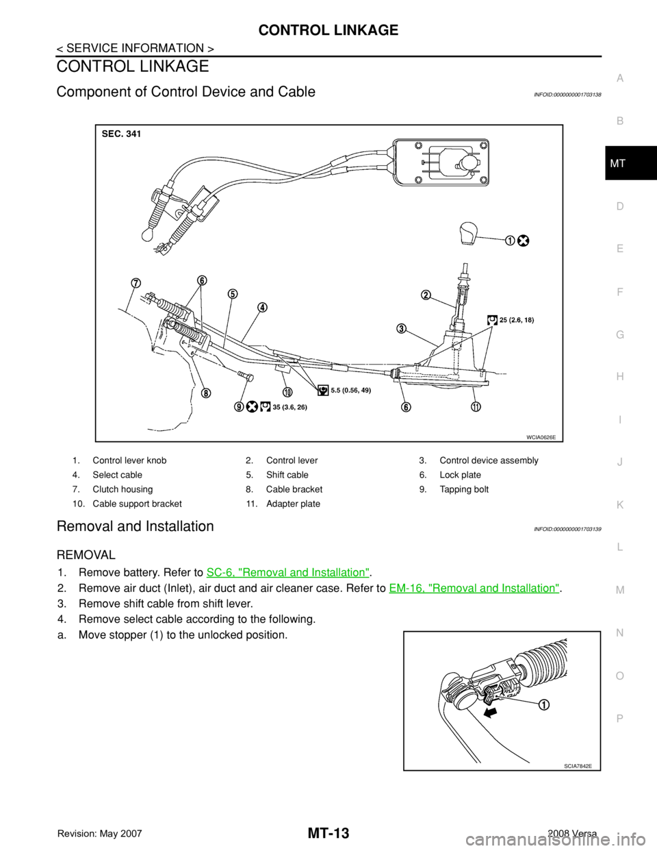
Component of Control Device and CableINFOID:0000000001703138
Removal and InstallationINFOID:0000000001703139
REMOVAL
1. Remove battery. Refer to SC-6, "Removal and Installation".
2. Remove air duct (Inlet), air duct and air cleaner case. Refer to EM-16, "
Removal and Installation".
3. Remove shift cable from shift lever.
4. Remove select cable according to the following.
a. Move stopper (1) to the unlocked position.
1. Control lever knob 2. Control lever 3. Control device assembly
4. Select cable 5. Shift cable 6. Lock plate
7. Clutch housing 8. Cable bracket 9. Tapping bolt
10. Cable support bracket 11. Adapter plate
WCIA0626E
SCIA7842E
Page 2303 of 2771
AIR BREATHER HOSE
MT-15
< SERVICE INFORMATION >
D
E
F
G
H
I
J
K
L
MA
B
MT
N
O
P
AIR BREATHER HOSE
Removal and InstallationINFOID:0000000001703140
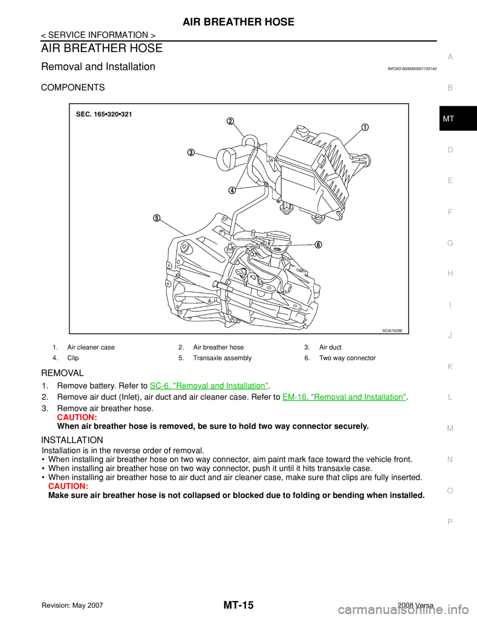
COMPONENTS
REMOVAL
1. Remove battery. Refer to SC-6, "Removal and Installation".
2. Remove air duct (Inlet), air duct and air cleaner case. Refer to EM-16, "
Removal and Installation".
3. Remove air breather hose.
CAUTION:
When air breather hose is removed, be sure to hold two way connector securely.
INSTALLATION
Installation is in the reverse order of removal.
• When installing air breather hose on two way connector, aim paint mark face toward the vehicle front.
• When installing air breather hose on two way connector, push it until it hits transaxle case.
• When installing air breather hose to air duct and air cleaner case, make sure that clips are fully inserted.
CAUTION:
Make sure air breather hose is not collapsed or blocked due to folding or bending when installed.
1. Air cleaner case 2. Air breather hose 3. Air duct
4. Clip 5. Transaxle assembly 6. Two way connector
SCIA7629E