2008 NISSAN TIIDA meter
[x] Cancel search: meterPage 966 of 2771
DTC P1722 ESTM VEHICLE SPEED SIGNAL
CVT-127
< SERVICE INFORMATION >
D
E
F
G
H
I
J
K
L
MA
B
CVT
N
O
P
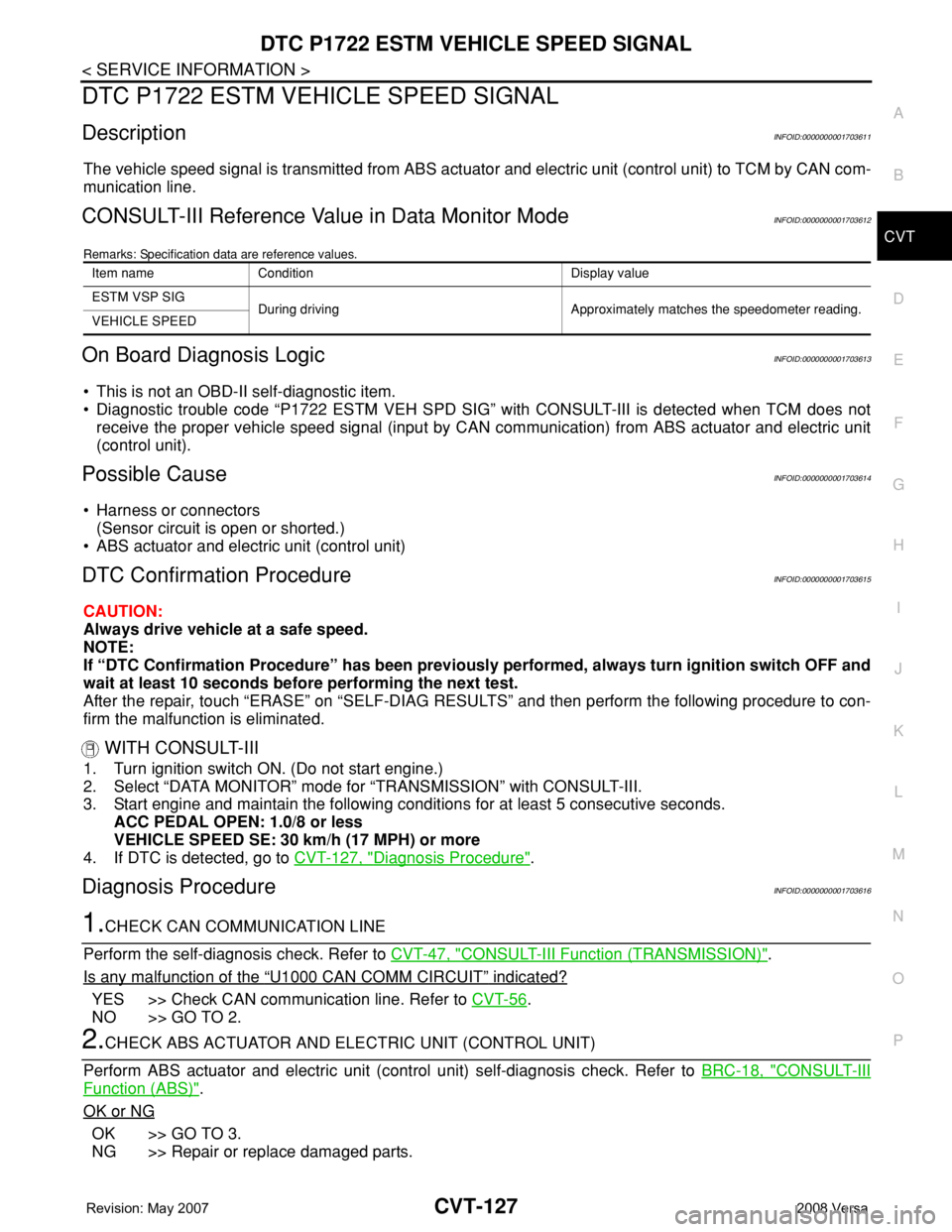
DTC P1722 ESTM VEHICLE SPEED SIGNAL
DescriptionINFOID:0000000001703611
The vehicle speed signal is transmitted from ABS actuator and electric unit (control unit) to TCM by CAN com-
munication line.
CONSULT-III Reference Value in Data Monitor ModeINFOID:0000000001703612
Remarks: Specification data are reference values.
On Board Diagnosis LogicINFOID:0000000001703613
• This is not an OBD-II self-diagnostic item.
• Diagnostic trouble code “P1722 ESTM VEH SPD SIG” with CONSULT-III is detected when TCM does not
receive the proper vehicle speed signal (input by CAN communication) from ABS actuator and electric unit
(control unit).
Possible CauseINFOID:0000000001703614
• Harness or connectors
(Sensor circuit is open or shorted.)
• ABS actuator and electric unit (control unit)
DTC Confirmation ProcedureINFOID:0000000001703615
CAUTION:
Always drive vehicle at a safe speed.
NOTE:
If “DTC Confirmation Procedure” has been previously performed, always turn ignition switch OFF and
wait at least 10 seconds before performing the next test.
After the repair, touch “ERASE” on “SELF-DIAG RESULTS” and then perform the following procedure to con-
firm the malfunction is eliminated.
WITH CONSULT-III
1. Turn ignition switch ON. (Do not start engine.)
2. Select “DATA MONITOR” mode for “TRANSMISSION” with CONSULT-III.
3. Start engine and maintain the following conditions for at least 5 consecutive seconds.
ACC PEDAL OPEN: 1.0/8 or less
VEHICLE SPEED SE: 30 km/h (17 MPH) or more
4. If DTC is detected, go to CVT-127, "
Diagnosis Procedure".
Diagnosis ProcedureINFOID:0000000001703616
1.CHECK CAN COMMUNICATION LINE
Perform the self-diagnosis check. Refer to CVT-47, "
CONSULT-III Function (TRANSMISSION)".
Is any malfunction of the
“U1000 CAN COMM CIRCUIT” indicated?
YES >> Check CAN communication line. Refer to CVT-56.
NO >> GO TO 2.
2.CHECK ABS ACTUATOR AND ELECTRIC UNIT (CONTROL UNIT)
Perform ABS actuator and electric unit (control unit) self-diagnosis check. Refer to BRC-18, "
CONSULT-III
Function (ABS)".
OK or NG
OK >> GO TO 3.
NG >> Repair or replace damaged parts.
Item name Condition Display value
ESTM VSP SIG
During driving Approximately matches the speedometer reading.
VEHICLE SPEED
Page 967 of 2771
CVT-128
< SERVICE INFORMATION >
DTC P1722 ESTM VEHICLE SPEED SIGNAL
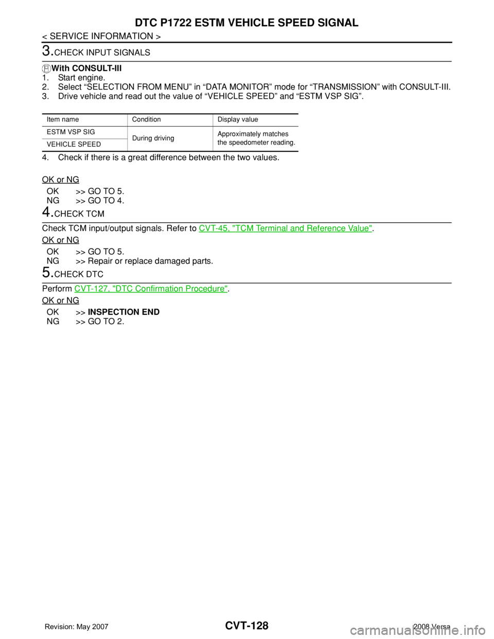
3.CHECK INPUT SIGNALS
With CONSULT-III
1. Start engine.
2. Select “SELECTION FROM MENU” in “DATA MONITOR” mode for “TRANSMISSION” with CONSULT-III.
3. Drive vehicle and read out the value of “VEHICLE SPEED” and “ESTM VSP SIG”.
4. Check if there is a great difference between the two values.
OK or NG
OK >> GO TO 5.
NG >> GO TO 4.
4.CHECK TCM
Check TCM input/output signals. Refer to CVT-45, "
TCM Terminal and Reference Value".
OK or NG
OK >> GO TO 5.
NG >> Repair or replace damaged parts.
5.CHECK DTC
Perform CVT-127, "
DTC Confirmation Procedure".
OK or NG
OK >>INSPECTION END
NG >> GO TO 2.
Item name Condition Display value
ESTM VSP SIG
During drivingApproximately matches
the speedometer reading.
VEHICLE SPEED
Page 984 of 2771
OVERDRIVE CONTROL SWITCH
CVT-145
< SERVICE INFORMATION >
D
E
F
G
H
I
J
K
L
MA
B
CVT
N
O
P
Perform the self-diagnosis check. Refer to CVT-47, "CONSULT-III Function (TRANSMISSION)".
Is any malfunction of the
“U1000 CAN COMM CIRCUIT” indicated in the results?
YES >> Check CAN communication line. Refer to CVT-56.
NO >> GO TO 2.
2.CHECK OVERDRIVE CONTROL SWITCH SIGNAL
With CONSULT-III
1. Turn ignition switch ON.
2. Select “ECU INPUT SIGNALS” in “DATA MONITOR” mode for “TRANSMISSION” with CONSULT-III.
3. Read out ON/OFF switching action of the “SPORT MODE SW”.
OK or NG
OK >>INSPECTION END
NG >> GO TO 3.
3.CHECK OVERDRIVE CONTROL SWITCH
Check overdrive control switch. Refer to CVT-146, "
Component Inspection"
OK or NG
OK >> GO TO 4.
NG >> Repair or replace damaged parts.
4.CHECK SELF-DIAGNOSTIC RESULTS (COMBINATION METER)
Perform self-diagnosis check. Refer to DI-11, "
Self-Diagnosis Mode of Combination Meter".
Is any malfunction detected by self-diagnostic?
YES >> Check the malfunctioning system.
NO - 1 >> With intelligent key: GO TO 5.
NO - 2 >> Without intelligent key: GO TO 6.
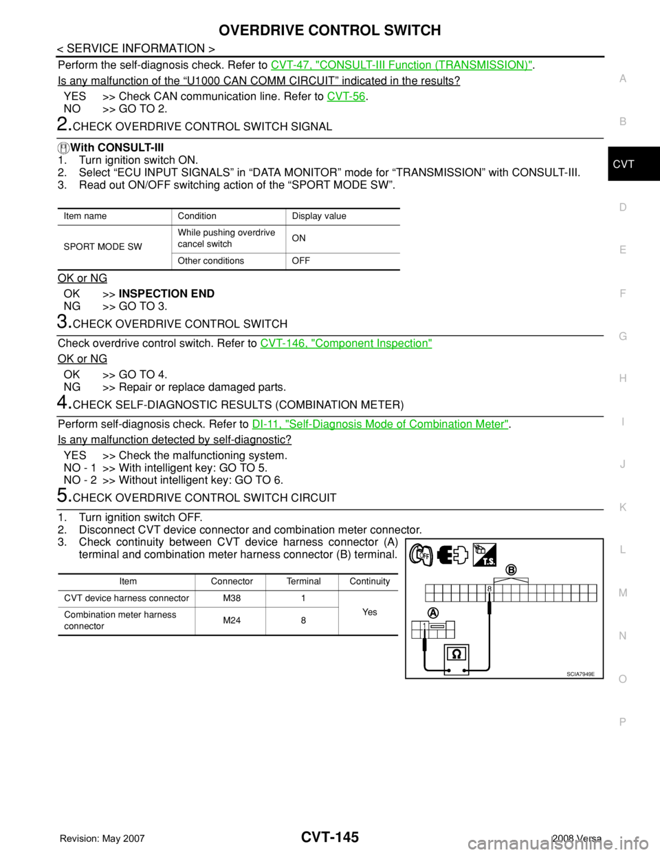
5.CHECK OVERDRIVE CONTROL SWITCH CIRCUIT
1. Turn ignition switch OFF.
2. Disconnect CVT device connector and combination meter connector.
3. Check continuity between CVT device harness connector (A)
terminal and combination meter harness connector (B) terminal.
Item name Condition Display value
SPORT MODE SWWhile pushing overdrive
cancel switchON
Other conditions OFF
Item Connector Terminal Continuity
CVT device harness connector M38 1
Ye s
Combination meter harness
connectorM24 8
SCIA7949E
Page 985 of 2771
CVT-146
< SERVICE INFORMATION >
OVERDRIVE CONTROL SWITCH
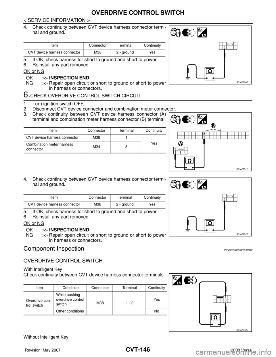
4. Check continuity between CVT device harness connector termi-
nal and ground.
5. If OK, check harness for short to ground and short to power.
6. Reinstall any part removed.
OK or NG
OK >>INSPECTION END
NG >> Repair open circuit or short to ground or short to power
in harness or connectors.
6.CHECK OVERDRIVE CONTROL SWITCH CIRCUIT
1. Turn ignition switch OFF.
2. Disconnect CVT device connector and combination meter connector.
3. Check continuity between CVT device harness connector (A)
terminal and combination meter harness connector (B) terminal.
4. Check continuity between CVT device harness connector termi-
nal and ground.
5. If OK, check harness for short to ground and short to power.
6. Reinstall any part removed.
OK or NG
OK >>INSPECTION END
NG >> Repair open circuit or short to ground or short to power
in harness or connectors.
Component InspectionINFOID:0000000001703658
OVERDRIVE CONTROL SWITCH
With Intelligent Key
Check continuity between CVT device harness connector terminals.
Without Intelligent Key
Item Connector Terminal Continuity
CVT device harness connector M38 2 - ground Yes
SCIA7950E
Item Connector Terminal Continuity
CVT device harness connector M38 1
Ye s
Combination meter harness
connectorM24 8
SCIA7951E
Item Connector Terminal Continuity
CVT device harness connector M38 2 - ground Yes
SCIA7952E
Item Condition Connector Terminal Continuity
Overdrive con-
trol switchWhile pushing
overdrive control
switchM38 1 - 2Ye s
Other conditions No
SCIA7942E
Page 987 of 2771
CVT-148
< SERVICE INFORMATION >
SHIFT POSITION INDICATOR CIRCUIT
SHIFT POSITION INDICATOR CIRCUIT
DescriptionINFOID:0000000001703659
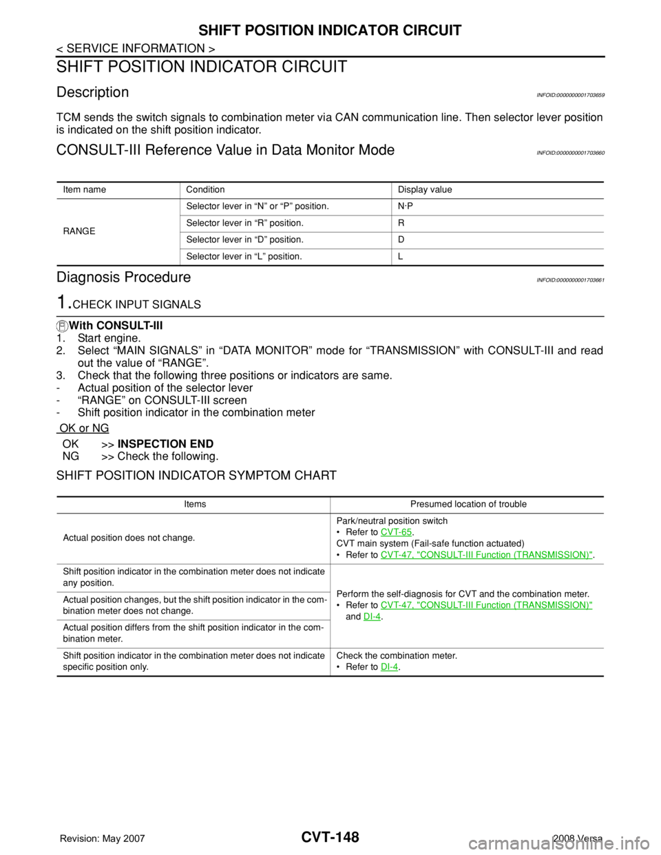
TCM sends the switch signals to combination meter via CAN communication line. Then selector lever position
is indicated on the shift position indicator.
CONSULT-III Reference Value in Data Monitor ModeINFOID:0000000001703660
Diagnosis ProcedureINFOID:0000000001703661
1.CHECK INPUT SIGNALS
With CONSULT-III
1. Start engine.
2. Select “MAIN SIGNALS” in “DATA MONITOR” mode for “TRANSMISSION” with CONSULT-III and read
out the value of “RANGE”.
3. Check that the following three positions or indicators are same.
- Actual position of the selector lever
- “RANGE” on CONSULT-III screen
- Shift position indicator in the combination meter
OK or NG
OK >>INSPECTION END
NG >> Check the following.
SHIFT POSITION INDICATOR SYMPTOM CHART
Item name Condition Display value
RANGESelector lever in “N” or “P” position. N·P
Selector lever in “R” position. R
Selector lever in “D” position. D
Selector lever in “L” position. L
Items Presumed location of trouble
Actual position does not change.Park/neutral position switch
• Refer to CVT-65
.
CVT main system (Fail-safe function actuated)
• Refer to CVT-47, "
CONSULT-III Function (TRANSMISSION)".
Shift position indicator in the combination meter does not indicate
any position.
Perform the self-diagnosis for CVT and the combination meter.
• Refer to CVT-47, "
CONSULT-III Function (TRANSMISSION)"
and DI-4
. Actual position changes, but the shift position indicator in the com-
bination meter does not change.
Actual position differs from the shift position indicator in the com-
bination meter.
Shift position indicator in the combination meter does not indicate
specific position only.Check the combination meter.
• Refer to DI-4
.
Page 992 of 2771
TROUBLE DIAGNOSIS FOR SYMPTOMS
CVT-153
< SERVICE INFORMATION >
D
E
F
G
H
I
J
K
L
MA
B
CVT
N
O
P
Check again. Refer to CVT-41, "Check before Engine Is Started".
OK or NG
OK >>INSPECTION END
NG >> GO TO 7.
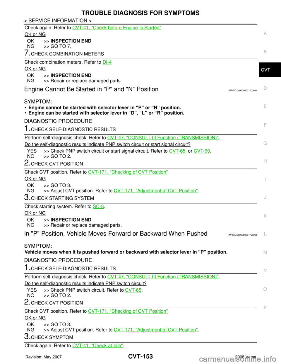
7.CHECK COMBINATION METERS
Check combination meters. Refer to DI-4
OK or NG
OK >>INSPECTION END
NG >> Repair or replace damaged parts.
Engine Cannot Be Started in "P" and "N" PositionINFOID:0000000001703664
SYMPTOM:
•Engine cannot be started with selector lever in “P” or “N” position.
•Engine can be started with selector lever in “D”, “L” or “R” position.
DIAGNOSTIC PROCEDURE
1.CHECK SELF-DIAGNOSTIC RESULTS
Perform self-diagnosis check. Refer to CVT-47, "
CONSULT-III Function (TRANSMISSION)".
Do the self-diagnostic results indicate PNP switch circuit or start signal circuit?
YES >> Check PNP switch circuit or start signal circuit. Refer to CVT-65 or CVT-60.
NO >> GO TO 2.
2.CHECK CVT POSITION
Check CVT position. Refer to CVT-171, "
Checking of CVT Position"
OK or NG
OK >> GO TO 3.
NG >> Adjust CVT position. Refer to CVT-171, "
Adjustment of CVT Position".
3.CHECK STARTING SYSTEM
Check starting system. Refer to SC-8
.
OK or NG
OK >>INSPECTION END
NG >> Repair or replace damaged parts.
In "P" Position, Vehicle Moves Forward or Backward When PushedINFOID:0000000001703665
SYMPTOM:
Vehicle moves when it is pushed forward or backward with selector lever in “P” position.
DIAGNOSTIC PROCEDURE
1.CHECK SELF-DIAGNOSTIC RESULTS
Perform self-diagnosis check. Refer to CVT-47, "
CONSULT-III Function (TRANSMISSION)".
Do the self-diagnostic results indicate PNP switch circuit?
YES >> Check PNP switch circuit. Refer to CVT-65.
NO >> GO TO 2.
2.CHECK CVT POSITION
Check CVT position. Refer to CVT-171, "
Checking of CVT Position"
OK or NG
OK >> GO TO 3.
NG >> Adjust CVT position. Refer to CVT-171, "
Adjustment of CVT Position".
3.CHECK SYMPTOM
Check again. Refer to CVT-41, "
Check at Idle".
Page 1022 of 2771

DI-1
ELECTRICAL
C
D
E
F
G
H
I
J
L
M
SECTION DI
A
B
DI
N
O
P
CONTENTS
DRIVER INFORMATION SYSTEM
SERVICE INFORMATION ............................2
PRECAUTION .....................................................2
Precaution for Supplemental Restraint System
(SRS) "AIR BAG" and "SEAT BELT PRE-TEN-
SIONER" ...................................................................
2
PREPARATION ...................................................3
Commercial Service Tool ..........................................3
COMBINATION METERS ...................................4
Component Parts and Harness Connector Loca-
tion ............................................................................
4
System Description ...................................................4
Arrangement of Combination Meter ..........................6
Internal Circuit ...........................................................7
Wiring Diagram - METER - .......................................8
Combination Meter Harness Connector Terminal
Layout .....................................................................
10
Terminal and Reference Value for Combination
Meter .......................................................................
10
Self-Diagnosis Mode of Combination Meter ............11
CONSULT-III Function (METER/M&A) ...................13
Trouble Diagnosis ...................................................14
Symptom Chart .......................................................15
Power Supply and Ground Circuit Inspection .........15
Vehicle Speed Signal Inspection .............................16
Engine Speed Signal Inspection .............................17
Fuel Level Sensor Signal Inspection .......................17
Fuel Gauge Fluctuates, Indicates Wrong Value, or
Varies ......................................................................
19
Fuel Gauge Does Not Move to Full-position ...........19
DTC [U1000] CAN Communication Circuit .............19
Electrical Component Inspection .............................19
Removal and Installation .........................................20
WARNING LAMPS .............................................21
Schematic ................................................................21
Wiring Diagram - WARN - .......................................22
Oil Pressure Warning Lamp Stays Off (Ignition
Switch ON) ..............................................................
30
Oil Pressure Warning Lamp Does Not Turn Off
(Oil Pressure Is Normal) ..........................................
32
Component Inspection .............................................32
A/T INDICATOR ................................................34
System Description ..................................................34
Wiring Diagram - AT/IND - .......................................35
A/T Indicator Does Not Illuminate ............................36
CVT INDICATOR ...............................................38
System Description ..................................................38
Wiring Diagram - CVTIND - .....................................38
CVT Indicator Does Not Illuminate ..........................39
WARNING CHIME .............................................41
Component Parts and Harness Connector Loca-
tion ...........................................................................
41
System Description ..................................................41
Wiring Diagram - CHIME - .......................................44
Terminal and Reference Value for BCM ..................45
CONSULT-III Function (BCM) .................................45
Trouble Diagnosis ....................................................46
Combination Meter Buzzer Circuit Inspection .........47
Front Door Switch LH Signal Inspection ..................48
Key Switch Signal Inspection (Without Intelligent
Key) .........................................................................
49
Key Switch and Ignition Knob Switch Signal In-
spection (With Intelligent Key, When Mechanical
Key Is Used) ............................................................
50
Lighting Switch Signal Inspection ............................52
Parking Brake Switch Signal Inspection ..................52
Electrical Component Inspection .............................53
Page 1025 of 2771
DI-4
< SERVICE INFORMATION >
COMBINATION METERS
COMBINATION METERS
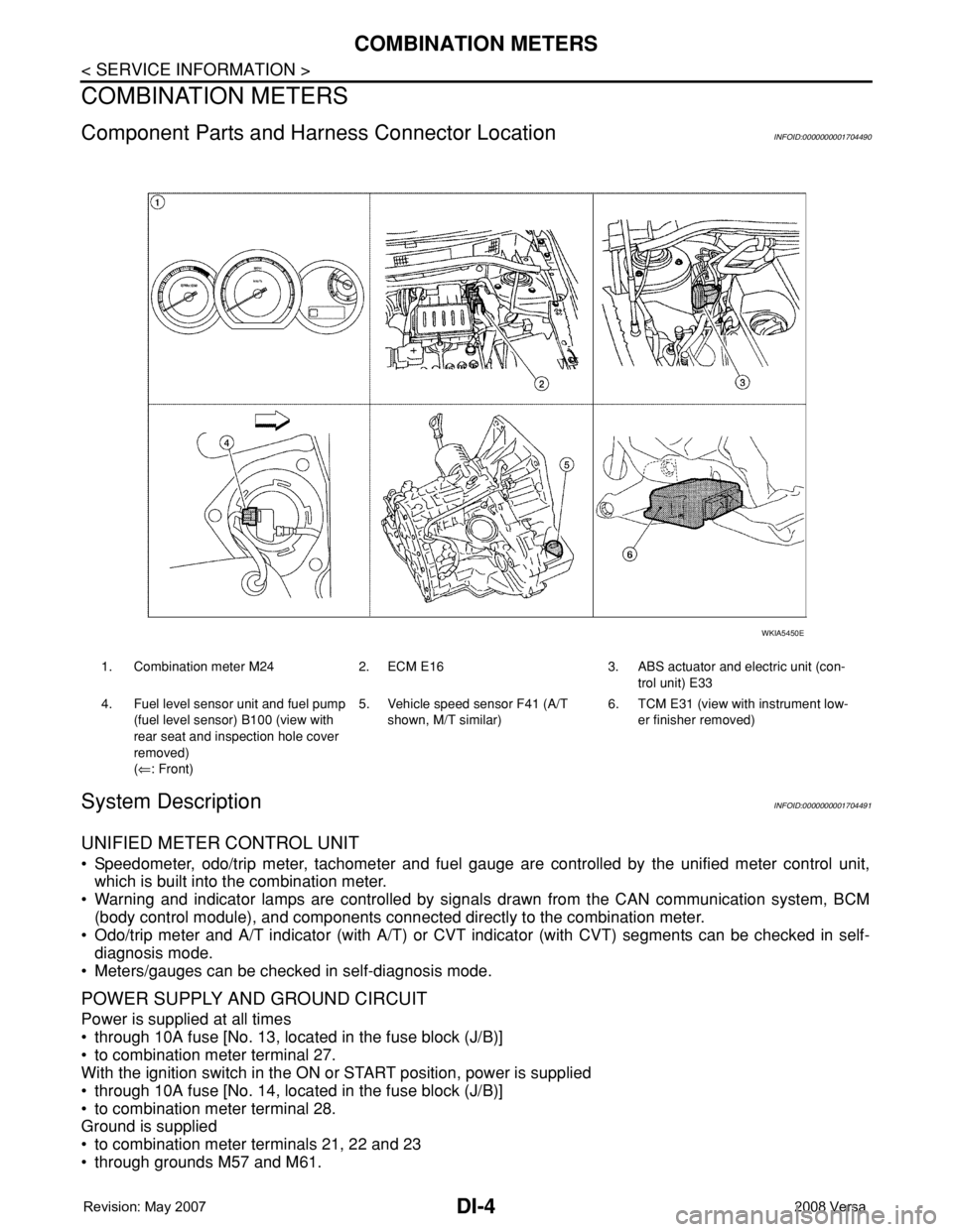
Component Parts and Harness Connector LocationINFOID:0000000001704490
System DescriptionINFOID:0000000001704491
UNIFIED METER CONTROL UNIT
• Speedometer, odo/trip meter, tachometer and fuel gauge are controlled by the unified meter control unit,
which is built into the combination meter.
• Warning and indicator lamps are controlled by signals drawn from the CAN communication system, BCM
(body control module), and components connected directly to the combination meter.
• Odo/trip meter and A/T indicator (with A/T) or CVT indicator (with CVT) segments can be checked in self-
diagnosis mode.
• Meters/gauges can be checked in self-diagnosis mode.
POWER SUPPLY AND GROUND CIRCUIT
Power is supplied at all times
• through 10A fuse [No. 13, located in the fuse block (J/B)]
• to combination meter terminal 27.
With the ignition switch in the ON or START position, power is supplied
• through 10A fuse [No. 14, located in the fuse block (J/B)]
• to combination meter terminal 28.
Ground is supplied
• to combination meter terminals 21, 22 and 23
• through grounds M57 and M61.
1. Combination meter M24 2. ECM E16 3. ABS actuator and electric unit (con-
trol unit) E33
4. Fuel level sensor unit and fuel pump
(fuel level sensor) B100 (view with
rear seat and inspection hole cover
removed)
(⇐: Front)5. Vehicle speed sensor F41 (A/T
shown, M/T similar)6. TCM E31 (view with instrument low-
er finisher removed)
WKIA5450E