2008 NISSAN TIIDA Mirrors
[x] Cancel search: MirrorsPage 1 of 2771

-1
QUICK REFERENCE INDEX
AGENERAL INFORMATIONGIGeneral Information
BENGINEEMEngine Mechanical
LUEngine Lubrication System
COEngine Cooling System
ECEngine Control System
FLFuel System
EXExhaust System
ACCAccelerator Control System
CTRANSMISSION/
TRANSAXLECLClutch System
MTManual Transaxle
ATAutomatic Transaxle
CVTCVT
DDRIVELINE/AXLEFAXFront Axle
RAXRear Axle
ESUSPENSIONFSUFront Suspension
RSURear Suspension
WTRoad Wheels & Tires
FBRAKESBRBrake System
PBParking Brake System
BRCBrake Control System
GSTEERINGPSPower Steering System
STCSteering Control System
HRESTRAINTSSBSeat Belts
SRSSupplemental Restraint System (SRS)
IBODYBLBody, Lock & Security System
GWGlasses, Window System & Mirrors
RFRoof
EIExterior & Interior
IPInstrument Panel
SESeat
JAIR CONDITIONERMTCManual Air Conditioner
KELECTRICALSCStarting & Charging System
LTLighting System
DIDriver Information System
WWWiper, Washer & Horn
BCSBody Control System
LANLAN System
AVAudio Visual, Navigation & Telephone System
ACSAuto Cruise Control System
PGPower Supply, Ground & Circuit Elements
LMAINTENANCEMAMaintenance
Edition: May 2007
Revision: May 2007
Publication No. SM8E-1C11U0
B
D
© 2007 NISSAN NORTH AMERICA, INC.
All rights reserved. No part of this Service Manual may be reproduced or stored in a retrieval system, or transmitted in any
form, or by any means, electronic, mechanical, photo-copying, recording or otherwise, without the prior written permission
of Nissan North America Inc.
A
C
E
F
G
H
I
J
K
L
M
Page 1893 of 2771

GI-42
< SERVICE INFORMATION >
RECOMMENDED CHEMICAL PRODUCTS AND SEALANTS
RECOMMENDED CHEMICAL PRODUCTS AND SEALANTS
Recommended Chemical Product and SealantINFOID:0000000001702455
Refer to the following chart for help in selecting the appropriate chemical product or sealant.
Product Description PurposeNissan North America
Part No. (USA)Nissan Canada Part
No. (Canada)Aftermarket Cross-
reference Part Nos.
1Rear View Mirror Adhe-
siveUsed to permanently re-
mount rear view mirrors to
windows.999MP-AM000P 99998-50505 Permatex 81844
2Anaerobic Liquid Gas-
ketFor metal-to-metal flange
sealing.
Can fill a 0.38 mm (0.015
inch) gap and provide in-
stant sealing for most pow-
ertrain applications.999MP-AM001P 99998-50503Permatex 51813 and
51817
3High Performance
Thread SealantProvides instant sealing on
any threaded straight or
parallel threaded fitting.
(Thread sealant only, no
locking ability.)
• Do not use on plastic.999MP-AM002P 999MP-AM002P Permatex 56521
4 Silicone RTVGasket Maker999MP-AM003P
(Ultra Grey)99998-50506
(Ultra Grey)Permatex Ultra Grey
82194;
Three Bond
1207,1215, 1216,
1217F, 1217G and
1217H
Nissan RTV Part No.
999MP-A7007
Gasket Maker for Maxima/
Quest 5-speed automatic
transmission
(RE5F22A)––Three Bond 1281B
or exact equivalent in
its quality
5High Temperature,
High Strength Thread
Locking Sealant (Red)Threadlocker 999MP-AM004P 999MP-AM004PPermatex 27200;
Three Bond 1360,
1360N, 1305 N&P,
1307N, 1335,
1335B, 1363B,
1377C, 1386B, D&E
and 1388
Loctite 648
6Medium Strength
Thread Locking Seal-
ant (Blue)Threadlocker (service tool
removable)999MP-AM005P 999MP-AM005PPermatex 24200,
24206, 24240,
24283 and 09178;
Three Bond 1322,
1322N, 1324 D&N,
1333D, 1361C,
1364D, 1370C and
1374
Page 1902 of 2771
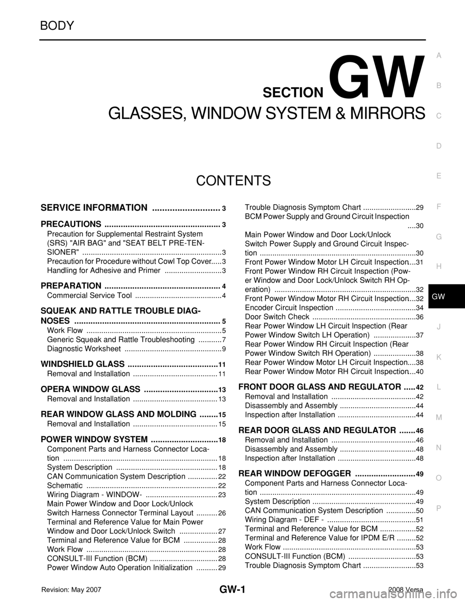
GW-1
BODY
C
D
E
F
G
H
J
K
L
M
SECTION GW
A
B
GW
N
O
P
CONTENTS
GLASSES, WINDOW SYSTEM & MIRRORS
SERVICE INFORMATION ............................3
PRECAUTIONS ...................................................3
Precaution for Supplemental Restraint System
(SRS) "AIR BAG" and "SEAT BELT PRE-TEN-
SIONER" ...................................................................
3
Precaution for Procedure without Cowl Top Cover ......3
Handling for Adhesive and Primer ............................3
PREPARATION ...................................................4
Commercial Service Tool ..........................................4
SQUEAK AND RATTLE TROUBLE DIAG-
NOSES ................................................................
5
Work Flow .................................................................5
Generic Squeak and Rattle Troubleshooting ............7
Diagnostic Worksheet ...............................................9
WINDSHIELD GLASS ........................................11
Removal and Installation .........................................11
OPERA WINDOW GLASS .................................13
Removal and Installation .........................................13
REAR WINDOW GLASS AND MOLDING .........15
Removal and Installation .........................................15
POWER WINDOW SYSTEM ..............................18
Component Parts and Harness Connector Loca-
tion ..........................................................................
18
System Description .................................................18
CAN Communication System Description ...............22
Schematic ...............................................................22
Wiring Diagram - WINDOW- ...................................23
Main Power Window and Door Lock/Unlock
Switch Harness Connector Terminal Layout ...........
26
Terminal and Reference Value for Main Power
Window and Door Lock/Unlock Switch ...................
27
Terminal and Reference Value for BCM .................28
Work Flow ...............................................................28
CONSULT-III Function (BCM) .................................28
Power Window Auto Operation Initialization ...........29
Trouble Diagnosis Symptom Chart ..........................29
BCM Power Supply and Ground Circuit Inspection
....
30
Main Power Window and Door Lock/Unlock
Switch Power Supply and Ground Circuit Inspec-
tion ...........................................................................
30
Front Power Window Motor LH Circuit Inspection ....31
Front Power Window RH Circuit Inspection (Pow-
er Window and Door Lock/Unlock Switch RH Op-
eration) ....................................................................
32
Front Power Window Motor RH Circuit Inspection ....32
Encoder Circuit Inspection .......................................34
Door Switch Check ..................................................36
Rear Power Window LH Circuit Inspection (Rear
Power Window Switch LH Operation) .....................
37
Rear Power Window RH Circuit Inspection (Rear
Power Window Switch RH Operation) .....................
38
Rear Power Window Motor LH Circuit Inspection ....38
Rear Power Window Motor RH Circuit Inspection ....40
FRONT DOOR GLASS AND REGULATOR .....42
Removal and Installation .........................................42
Disassembly and Assembly .....................................44
Inspection after Installation ......................................44
REAR DOOR GLASS AND REGULATOR .......46
Removal and Installation .........................................46
Disassembly and Assembly .....................................48
Inspection after Installation ......................................48
REAR WINDOW DEFOGGER ..........................49
Component Parts and Harness Connector Loca-
tion ...........................................................................
49
System Description ..................................................49
CAN Communication System Description ...............50
Wiring Diagram - DEF - ...........................................51
Terminal and Reference Value for BCM ..................52
Terminal and Reference Value for IPDM E/R ..........52
Work Flow ................................................................53
CONSULT-III Function (BCM) .................................53
Trouble Diagnosis Symptom Chart ..........................53
Page 1950 of 2771
REAR WINDOW DEFOGGER
GW-49
< SERVICE INFORMATION >
C
D
E
F
G
H
J
K
L
MA
B
GW
N
O
P
REAR WINDOW DEFOGGER
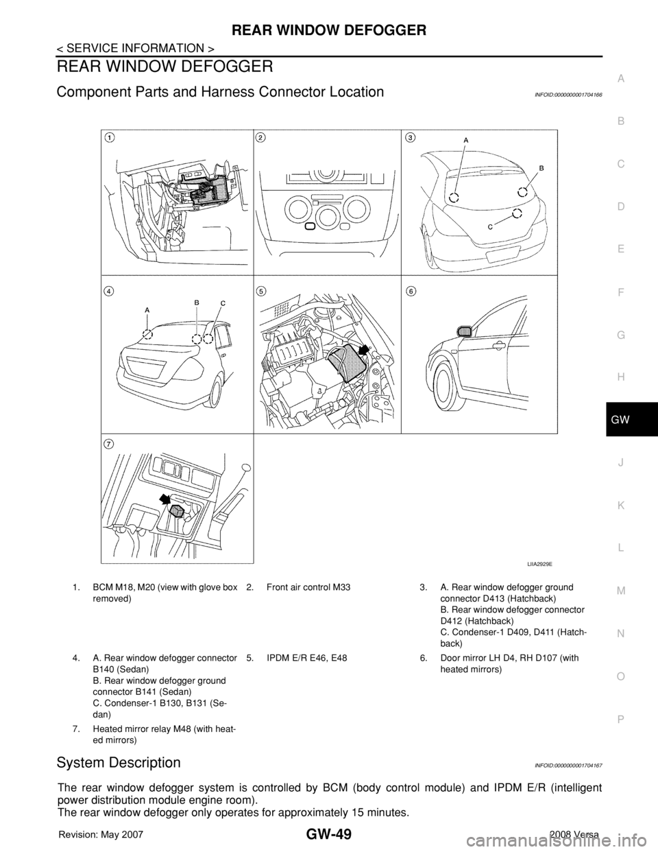
Component Parts and Harness Connector LocationINFOID:0000000001704166
System DescriptionINFOID:0000000001704167
The rear window defogger system is controlled by BCM (body control module) and IPDM E/R (intelligent
power distribution module engine room).
The rear window defogger only operates for approximately 15 minutes.
1. BCM M18, M20 (view with glove box
removed)2. Front air control M33 3. A. Rear window defogger ground
connector D413 (Hatchback)
B. Rear window defogger connector
D412 (Hatchback)
C. Condenser-1 D409, D411 (Hatch-
back)
4. A. Rear window defogger connector
B140 (Sedan)
B. Rear window defogger ground
connector B141 (Sedan)
C. Condenser-1 B130, B131 (Se-
dan)5. IPDM E/R E46, E48 6. Door mirror LH D4, RH D107 (with
heated mirrors)
7. Heated mirror relay M48 (with heat-
ed mirrors)
LIIA2929E
Page 1951 of 2771
GW-50
< SERVICE INFORMATION >
REAR WINDOW DEFOGGER
Power is supplied at all times
• through 15A fuses (No. 46 and 47, located in the IPDM E/R)
• to rear window defogger relay
• through 10A fuse [No. 5 (with heated mirrors), located in the fuse block (J/B)]
• to heated mirror relay terminal 3
• through 40A fusible link (letter g , located in the fuse and fusible link box)
• to BCM terminal 70.
With the ignition switch turned to ON or START position, power is supplied
• through ignition relay
• to rear window defogger relay (located in the IPDM E/R)
• through 10A fuse [No. 6, located in the fuse block (J/B)]
• to BCM terminal 38.
Ground is supplied
• to BCM terminal 67 and
• to front air control terminal 8
• through body grounds M57 and M61
• to IPDM E/R terminals 39 and 59
• through body grounds E15 and E24.
When front air control (rear window defogger switch) is turned to ON, ground is supplied
• to BCM terminal 9
• through front air control terminal 3
• through front air control terminal 8
• through body grounds M57 and M61.
Then rear window defogger switch is illuminated.
Then BCM recognizes that rear window defogger switch is turned to ON.
Then it sends rear window defogger switch signals to IPDM E/R via CAN communication (CAN-H, CAN-L).
When IPDM E/R receives rear window defogger switch signals, ground is supplied
• to rear window defogger relay (located in the IPDM E/R)
• through IPDM E/R terminals 39 and 59
• through body grounds E15 and E24
Then rear window defogger relay is energized.
With power and ground supplied, rear window defogger filaments heat and defog the rear window.
When rear window defogger relay is turned to ON (with heated mirrors), power is supplied
• through heated mirror relay terminal 5
• to door mirror (LH and RH) terminal 1.
Door mirror (LH and RH) is grounded through body grounds M57 and M61.
With power and ground supplied, rear window defogger filaments heat and defog the rear window and door
mirror filaments heat and defog the mirrors.
CAN Communication System DescriptionINFOID:0000000001704168
Refer to LAN-6, "System Description".
Page 1954 of 2771
REAR WINDOW DEFOGGER
GW-53
< SERVICE INFORMATION >
C
D
E
F
G
H
J
K
L
MA
B
GW
N
O
P
Work FlowINFOID:0000000001704172
1. Check the symptom and customer's requests.
2. Understand the outline of system. Refer to GW-49, "
System Description" .
3. According to the trouble diagnosis chart, repair or replace the cause of the malfunction. Refer to GW-53,
"Trouble Diagnosis Symptom Chart" .
4. Does rear window defogger operate normally? YES: GO TO 5, NO: GO TO 3.
5. Inspection End.
CONSULT-III Function (BCM)INFOID:0000000001704173
CONSULT-III can display each diagnostic item using the diagnostic test modes shown following.
DATA MONITOR
Display Item List
ACTIVE TEST
Display Item List
Trouble Diagnosis Symptom ChartINFOID:0000000001704174
Make sure other systems using the signal of the following systems operate normally.
BCM diagnostic
test itemDiagnostic mode Content
Inspection by partWORK SUPPORTSupports inspections and adjustments. Commands are transmitted to the BCM for
setting the status suitable for required operation, input/output signals are received
from the BCM and received data is displayed.
DATA MONITOR Displays BCM input/output data in real time.
ACTIVE TEST Operation of electrical loads can be checked by sending drive signal to them.
SELF-DIAG RESULTS Displays BCM self-diagnosis results.
CAN DIAG SUPPORT
MNTRThe results of transmit/receive diagnosis of CAN communication can be read.
ECU PART NUMBER BCM part number can be read.
CONFIGURATION Performs BCM configuration read/write functions.
Monitor item “Operation” Content
REAR DEF SW “ON/OFF” Indicates (ON/OFF) condition of the rear window defogger switch.
IGN ON SW “ON/OFF” Indicates (ON/OFF) condition of the ignition switch signal.
Test item Content
REAR WINDOW DEFOGGER Gives a drive signal to the rear window defogger to activate it.
Symptom Diagnoses / Service procedure Refer to page
Rear window defogger and door mirror defoggers do not
operate. (With heated mirrors)1. BCM power supply and ground circuit checkBCS-15
2. IPDM E/R auto active test checkPG-19
3. Rear window defogger switch circuit checkGW-54
4. Replace IPDM E/RPG-26
Page 1955 of 2771
GW-54
< SERVICE INFORMATION >
REAR WINDOW DEFOGGER
BCM Power Supply and Ground Circuit Inspection
INFOID:0000000001704175
Refer to BCS-15, "BCM Power Supply and Ground Circuit Inspection" .
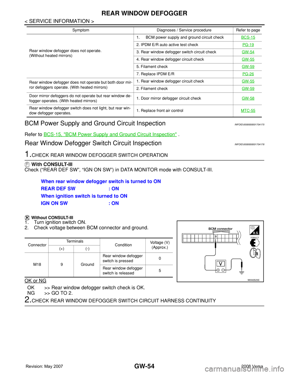
Rear Window Defogger Switch Circuit InspectionINFOID:0000000001704176
1.CHECK REAR WINDOW DEFOGGER SWITCH OPERATION
With CONSULT-III
Check (“REAR DEF SW”, “IGN ON SW”) in DATA MONITOR mode with CONSULT-III.
Without CONSULT-III
1. Turn ignition switch ON.
2. Check voltage between BCM connector and ground.
OK or NG
OK >> Rear window defogger switch check is OK.
NG >> GO TO 2.
2.CHECK REAR WINDOW DEFOGGER SWITCH CIRCUIT HARNESS CONTINUITY
Rear window defogger does not operate.
(Without heated mirrors)1. BCM power supply and ground circuit checkBCS-15
2. IPDM E/R auto active test checkPG-19
3. Rear window defogger switch circuit checkGW-54
4. Rear window defogger circuit checkGW-55
5. Filament checkGW-59
7. Replace IPDM E/RPG-26
Rear window defogger does not operate but both door mir-
ror defoggers operate. (With heated mirrors)1. Rear window defogger circuit checkGW-55
2. Filament checkGW-59
Door mirror defoggers do not operate but rear window de-
fogger operates. (With heated mirrors)1. Door mirror defogger circuit checkGW-58
Rear window defogger switch does not light, but rear win-
dow defogger operates.1. Replace front air controlMTC-55
Symptom Diagnoses / Service procedure Refer to page
When rear window defogger switch is turned to ON
REAR DEF SW : ON
When ignition switch is turned to ON
IGN ON SW : ON
ConnectorTe r m i n a l s
ConditionVoltage (V)
(Approx.)
(+) (-)
M18 9 GroundRear window defogger
switch is pressed0
Rear window defogger
switch is released5
WIIA0523E