2008 NISSAN TIIDA U1001
[x] Cancel search: U1001Page 1076 of 2771

EC-2
ECM Terminal and Reference Value .....................102
CONSULT-II Function (ENGINE) ..........................109
Generic Scan Tool (GST) Function .......................119
CONSULT-II Reference Value in Data Monitor
Mode ......................................................................
121
Major Sensor Reference Graph in Data Monitor
Mode ......................................................................
124
TROUBLE DIAGNOSIS - SPECIFICATION
VALUE .............................................................
127
Description .............................................................127
Testing Condition ...................................................127
Inspection Procedure .............................................127
Diagnosis Procedure .............................................127
TROUBLE DIAGNOSIS FOR INTERMITTENT
INCIDENT ........................................................
136
Description .............................................................136
Diagnosis Procedure .............................................136
POWER SUPPLY AND GROUND CIRCUIT ...137
Wiring Diagram ......................................................137
Diagnosis Procedure .............................................138
Ground Inspection .................................................142
DTC U1000, U1001 CAN COMMUNICATION
LINE .................................................................
143
Description .............................................................143
On Board Diagnosis Logic .....................................143
DTC Confirmation Procedure ................................143
Wiring Diagram ......................................................144
Diagnosis Procedure .............................................144
DTC U1010 CAN COMMUNICATION .............145
Description .............................................................145
On Board Diagnosis Logic .....................................145
DTC Confirmation Procedure ................................145
Diagnosis Procedure .............................................145
DTC P0011 IVT CONTROL .............................147
Description .............................................................147
CONSULT-II Reference Value in Data Monitor
Mode ......................................................................
147
On Board Diagnosis Logic .....................................148
DTC Confirmation Procedure ................................148
Diagnosis Procedure .............................................149
Component Inspection ...........................................150
Removal and Installation .......................................150
DTC P0031, P0032 A/F SENSOR 1 HEATER .151
Description .............................................................151
CONSULT-II Reference Value in Data Monitor
Mode ......................................................................
151
On Board Diagnosis Logic .....................................151
DTC Confirmation Procedure ................................151
Wiring Diagram ......................................................152
Diagnosis Procedure .............................................153
Component Inspection ...........................................154
Removal and Installation .......................................155
DTC P0037, P0038 HO2S2 HEATER ..............156
Description ............................................................156
CONSULT-II Reference Value in Data Monitor
Mode .....................................................................
156
On Board Diagnosis Logic ....................................156
DTC Confirmation Procedure ................................156
Wiring Diagram .....................................................158
Diagnosis Procedure .............................................159
Component Inspection ..........................................160
Removal and Installation .......................................161
DTC P0075 IVT CONTROL SOLENOID
VALVE ..............................................................
162
Component Description ........................................162
CONSULT-II Reference Value in Data Monitor
Mode .....................................................................
162
On Board Diagnosis Logic ....................................162
DTC Confirmation Procedure ................................162
Wiring Diagram .....................................................163
Diagnosis Procedure .............................................164
Component Inspection ..........................................165
Removal and Installation .......................................166
DTC P0101 MAF SENSOR ..............................167
Component Description ........................................167
CONSULT-II Reference Value in Data Monitor
Mode .....................................................................
167
On Board Diagnosis Logic ....................................167
DTC Confirmation Procedure ................................167
Overall Function Check .........................................169
Wiring Diagram .....................................................170
Diagnosis Procedure .............................................171
Component Inspection ..........................................173
Removal and Installation .......................................174
DTC P0102, P0103 MAF SENSOR ..................175
Component Description ........................................175
CONSULT-II Reference Value in Data Monitor
Mode .....................................................................
175
On Board Diagnosis Logic ....................................175
DTC Confirmation Procedure ................................175
Wiring Diagram .....................................................177
Diagnosis Procedure .............................................178
Component Inspection ..........................................180
Removal and Installation .......................................181
DTC P0112, P0113 IAT SENSOR ....................182
Component Description ........................................182
On Board Diagnosis Logic ....................................182
DTC Confirmation Procedure ................................182
Wiring Diagram .....................................................184
Diagnosis Procedure .............................................184
Component Inspection ..........................................186
Removal and Installation .......................................186
DTC P0117, P0118 ECT SENSOR ...................187
Component Description ........................................187
On Board Diagnosis Logic ....................................187
DTC Confirmation Procedure ................................188
Wiring Diagram .....................................................189
Page 1083 of 2771
INDEX FOR DTC
EC-9
< SERVICE INFORMATION >
C
D
E
F
G
H
I
J
K
L
MA
EC
N
P O
SERVICE INFORMATION
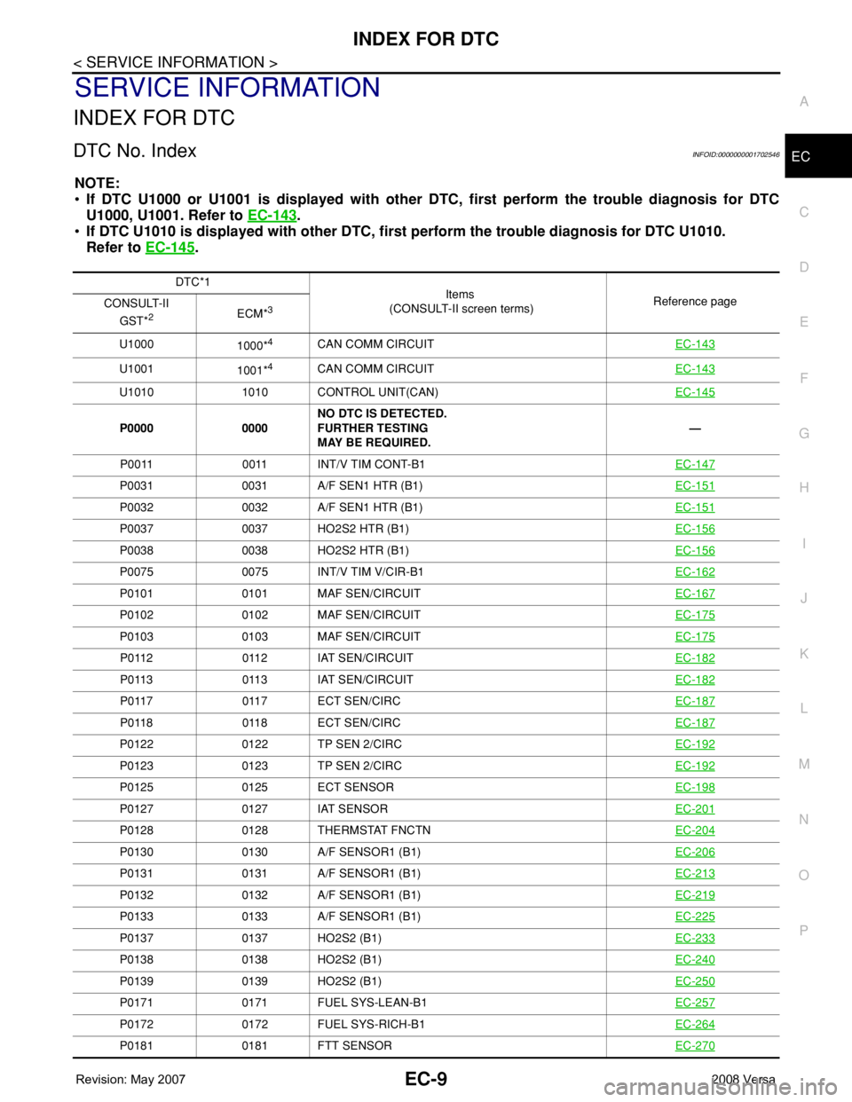
INDEX FOR DTC
DTC No. IndexINFOID:0000000001702546
NOTE:
•If DTC U1000 or U1001 is displayed with other DTC, first perform the trouble diagnosis for DTC
U1000, U1001. Refer to EC-143
.
•If DTC U1010 is displayed with other DTC, first perform the trouble diagnosis for DTC U1010.
Refer to EC-145
.
DTC*1
Items
(CONSULT-II screen terms)Reference page
CONSULT-II
GST*
2ECM*3
U1000
1000*4CAN COMM CIRCUITEC-143
U1001
1001*4CAN COMM CIRCUITEC-143
U1010 1010 CONTROL UNIT(CAN)EC-145
P0000 0000NO DTC IS DETECTED.
FURTHER TESTING
MAY BE REQUIRED.—
P0011 0011 INT/V TIM CONT-B1EC-147
P0031 0031 A/F SEN1 HTR (B1)EC-151
P0032 0032 A/F SEN1 HTR (B1)EC-151
P0037 0037 HO2S2 HTR (B1)EC-156
P0038 0038 HO2S2 HTR (B1)EC-156
P0075 0075 INT/V TIM V/CIR-B1EC-162
P0101 0101 MAF SEN/CIRCUITEC-167
P0102 0102 MAF SEN/CIRCUITEC-175
P0103 0103 MAF SEN/CIRCUITEC-175
P0112 0112 IAT SEN/CIRCUITEC-182
P0113 0113 IAT SEN/CIRCUITEC-182
P0117 0117 ECT SEN/CIRCEC-187
P0118 0118 ECT SEN/CIRCEC-187
P0122 0122 TP SEN 2/CIRCEC-192
P0123 0123 TP SEN 2/CIRCEC-192
P0125 0125 ECT SENSOREC-198
P0127 0127 IAT SENSOREC-201
P0128 0128 THERMSTAT FNCTNEC-204
P0130 0130 A/F SENSOR1 (B1)EC-206
P0131 0131 A/F SENSOR1 (B1)EC-213
P0132 0132 A/F SENSOR1 (B1)EC-219
P0133 0133 A/F SENSOR1 (B1)EC-225
P0137 0137 HO2S2 (B1)EC-233
P0138 0138 HO2S2 (B1)EC-240
P0139 0139 HO2S2 (B1)EC-250
P0171 0171 FUEL SYS-LEAN-B1EC-257
P0172 0172 FUEL SYS-RICH-B1EC-264
P0181 0181 FTT SENSOREC-270
Page 1086 of 2771
EC-12
< SERVICE INFORMATION >
INDEX FOR DTC
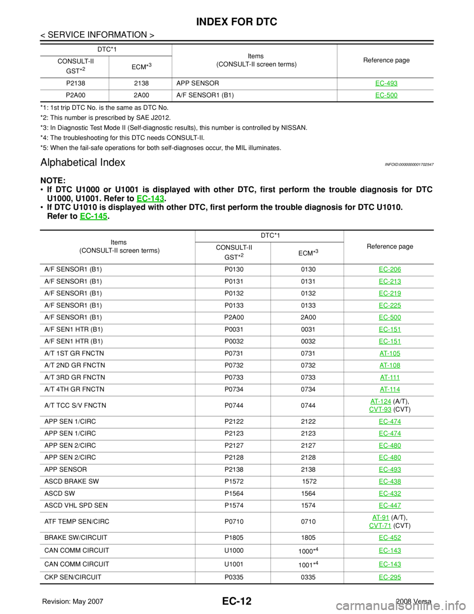
*1: 1st trip DTC No. is the same as DTC No.
*2: This number is prescribed by SAE J2012.
*3: In Diagnostic Test Mode II (Self-diagnostic results), this number is controlled by NISSAN.
*4: The troubleshooting for this DTC needs CONSULT-II.
*5: When the fail-safe operations for both self-diagnoses occur, the MIL illuminates.
Alphabetical IndexINFOID:0000000001702547
NOTE:
•If DTC U1000 or U1001 is displayed with other DTC, first perform the trouble diagnosis for DTC
U1000, U1001. Refer to EC-143
.
•If DTC U1010 is displayed with other DTC, first perform the trouble diagnosis for DTC U1010.
Refer to EC-145
.
P2138 2138 APP SENSOREC-493
P2A00 2A00 A/F SENSOR1 (B1)EC-500
DTC*1
Items
(CONSULT-II screen terms)Reference page
CONSULT-II
GST*
2ECM*3
Items
(CONSULT-II screen terms)DTC*1
Reference page
CONSULT-II
GST*
2ECM*3
A/F SENSOR1 (B1) P0130 0130EC-206
A/F SENSOR1 (B1) P0131 0131EC-213
A/F SENSOR1 (B1) P0132 0132EC-219
A/F SENSOR1 (B1) P0133 0133EC-225
A/F SENSOR1 (B1) P2A00 2A00EC-500
A/F SEN1 HTR (B1) P0031 0031EC-151
A/F SEN1 HTR (B1) P0032 0032EC-151
A/T 1ST GR FNCTN P0731 0731AT- 1 0 5
A/T 2ND GR FNCTN P0732 0732AT- 1 0 8
A/T 3RD GR FNCTN P0733 0733AT- 111
A/T 4TH GR FNCTN P0734 0734AT- 11 4
A/T TCC S/V FNCTN P0744 0744AT- 1 2 4 (A/T),
CVT-93
(CVT)
APP SEN 1/CIRC P2122 2122EC-474
APP SEN 1/CIRC P2123 2123EC-474
APP SEN 2/CIRC P2127 2127EC-480
APP SEN 2/CIRC P2128 2128EC-480
APP SENSOR P2138 2138EC-493
ASCD BRAKE SW P1572 1572EC-438
ASCD SW P1564 1564EC-432
ASCD VHL SPD SEN P1574 1574EC-447
ATF TEMP SEN/CIRC P0710 0710AT- 9 1 (A/T),
CVT-71
(CVT)
BRAKE SW/CIRCUIT P1805 1805EC-452
CAN COMM CIRCUIT U1000
1000*4EC-143
CAN COMM CIRCUIT U1001
1001*4EC-143
CKP SEN/CIRCUIT P0335 0335EC-295
Page 1121 of 2771
ON BOARD DIAGNOSTIC (OBD) SYSTEM
EC-47
< SERVICE INFORMATION >
C
D
E
F
G
H
I
J
K
L
MA
EC
N
P O
Therefore, when electrical controlled throttle and part of ECM related diagnoses are continuously detected as
NG for 5 trips, ECM warns the driver that engine control system malfunctions and MIL circuit is open by means
of operating fail-safe function.
The fail-safe function also operates when above diagnoses except MIL circuit are detected, and demands the
driver to repair the malfunction.
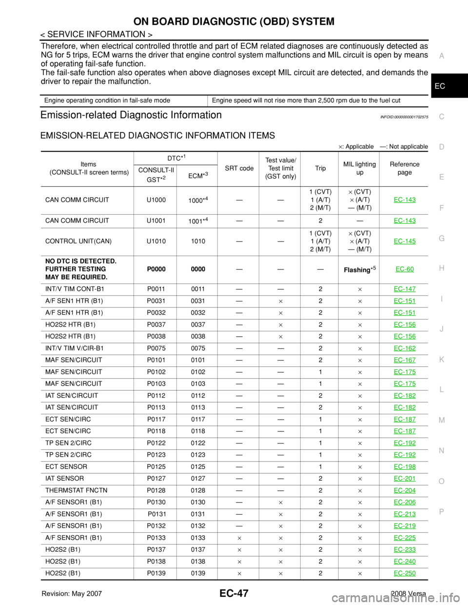
Emission-related Diagnostic InformationINFOID:0000000001702575
EMISSION-RELATED DIAGNOSTIC INFORMATION ITEMS
×: Applicable —: Not applicable
Engine operating condition in fail-safe mode Engine speed will not rise more than 2,500 rpm due to the fuel cut
Items
(CONSULT-II screen terms)DTC*
1
SRT codeTest value/
Test limit
(GST only)TripMIL lighting
upReference
page CONSULT-II
GST*
2ECM*3
CAN COMM CIRCUIT U1000
1000*4——1 (CVT)
1 (A/T)
2 (M/T)× (CVT)
× (A/T)
— (M/T)EC-143
CAN COMM CIRCUIT U1001
1001*4——2—EC-143
CONTROL UNIT(CAN) U1010 1010 — —1 (CVT)
1 (A/T)
2 (M/T)× (CVT)
× (A/T)
— (M/T)EC-145
NO DTC IS DETECTED.
FURTHER TESTING
MAY BE REQUIRED.P0000 0000———
Flashing*5EC-60
INT/V TIM CONT-B1 P0011 0011 — — 2×EC-147
A/F SEN1 HTR (B1) P0031 0031 —×2×EC-151
A/F SEN1 HTR (B1) P0032 0032 —×2×EC-151
HO2S2 HTR (B1) P0037 0037 —×2×EC-156
HO2S2 HTR (B1) P0038 0038 —×2×EC-156
INT/V TIM V/CIR-B1 P0075 0075 — — 2×EC-162
MAF SEN/CIRCUIT P0101 0101 — — 2×EC-167
MAF SEN/CIRCUIT P0102 0102 — — 1×EC-175
MAF SEN/CIRCUIT P0103 0103 — — 1×EC-175
IAT SEN/CIRCUIT P0112 0112 — — 2×EC-182
IAT SEN/CIRCUIT P0113 0113 — — 2×EC-182
ECT SEN/CIRC P0117 0117 — — 1×EC-187
ECT SEN/CIRC P0118 0118 — — 1×EC-187
TP SEN 2/CIRC P0122 0122 — — 1×EC-192
TP SEN 2/CIRC P0123 0123 — — 1×EC-192
ECT SENSOR P0125 0125 — — 1×EC-198
IAT SENSOR P0127 0127 — — 2×EC-201
THERMSTAT FNCTN P0128 0128 — — 2×EC-204
A/F SENSOR1 (B1) P0130 0130 —×2×EC-206
A/F SENSOR1 (B1) P0131 0131 —×2×EC-213
A/F SENSOR1 (B1) P0132 0132 —×2×EC-219
A/F SENSOR1 (B1) P0133 0133××2×EC-225
HO2S2 (B1) P0137 0137××2×EC-233
HO2S2 (B1) P0138 0138××2×EC-240
HO2S2 (B1) P0139 0139××2×EC-250
Page 1160 of 2771
EC-86
< SERVICE INFORMATION >
TROUBLE DIAGNOSIS
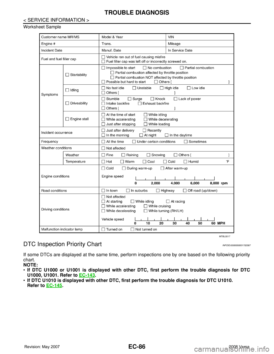
Worksheet Sample
DTC Inspection Priority ChartINFOID:0000000001702587
If some DTCs are displayed at the same time, perform inspections one by one based on the following priority
chart.
NOTE:
•If DTC U1000 or U1001 is displayed with other DTC, first perform the trouble diagnosis for DTC
U1000, U1001. Refer to EC-143
.
•If DTC U1010 is displayed with other DTC, first perform the trouble diagnosis for DTC U1010.
Refer to EC-145
.
MTBL0017
Page 1161 of 2771

TROUBLE DIAGNOSIS
EC-87
< SERVICE INFORMATION >
C
D
E
F
G
H
I
J
K
L
MA
EC
N
P O
Fail-Safe ChartINFOID:0000000001702588
When the DTC listed below is detected, the ECM enters fail-safe mode and the MIL lights up.
Priority Detected items (DTC)
1 • U1000 U1001 CAN communication line
• U1010 CAN communication
• P0101 P0102 P0103 Mass air flow sensor
• P0112 P0113 P0127 Intake air temperature sensor
• P0117 P0118 P0125 Engine coolant temperature sensor
• P0122 P0123 P0222 P0223 P1225 P1226 P2135 Throttle position sensor
• P0128 Thermostat function
• P0181 P0182 P0183 Fuel tank temperature sensor
• P0327 P0328 Knock sensor
• P0335 Crankshaft position sensor (POS)
• P0340 Camshaft position sensor (PHASE)
• P0460 P0461 P0462 P0463 Fuel level sensor
• P0500 Vehicle speed sensor
• P0605 ECM
• P0643 Sensor power supply
• P0705 P0850 Park/neutral position (PNP) switch
• P1610 - P1615 NATS
• P2122 P2123 P2127 P2128 P2138 Accelerator pedal position sensor
2 • P0031 P0032 Air fuel ratio (A/F) sensor 1 heater
• P0037 P0038 Heated oxygen sensor 2 heater
• P0075 Intake valve timing control solenoid valve
• P0130 P0131 P0132 P0133 P2A00 Air fuel ratio (A/F) sensor 1
• P0137 P0138 P0139 Heated oxygen sensor 2
• P0441 EVAP control system purge flow monitoring
• P0443 P0444 P0445 EVAP canister purge volume control solenoid valve
• P0447 P0448 EVAP canister vent control valve
• P0451 P0452 P0453 EVAP control system pressure sensor
• P1217 Engine over temperature (OVERHEAT)
• P1805 Brake switch
• P2100 P2103 Throttle control motor relay
• P2101 Electric throttle control function
• P2118 Throttle control motor
3 • P0011 Intake valve timing control
• P0171 P0172 Fuel injection system function
• P0300 - P0304 Misfire
• P0420 Three way catalyst function
• P0442 P0456 EVAP control system (SMALL LEAK, VERY SMALL LEAK)
• P0455 EVAP control system (GROSS LEAK)
• P0506 P0507 Idle speed control system
• P0710 P0715 P0720 P0725 P0731 P0732 P0733 P0734 P0740 P0744 P0745 P0746 P0750 P0755 P0776 P0778
P0840 P0845 P1705 P1740 P1760 P1777 P1778 A/T or CVT related sensors, solenoid valves and switches
• P1148 Closed loop control
• P1421 Cold start control
• P1564 ASCD steering switch
• P1572 ASCD brake switch
• P1574 ASCD vehicle speed sensor
• P1715 Turbine revolution sensor (A/T), Primary speed sensor (CVT)
• P2119 Electric throttle control actuator
DTC No. Detected items Engine operating condition in fail-safe mode
P0102
P0103Mass air flow sensor circuit Engine speed will not rise more than 2,400 rpm due to the fuel cut.
Page 1217 of 2771
DTC U1000, U1001 CAN COMMUNICATION LINE
EC-143
< SERVICE INFORMATION >
C
D
E
F
G
H
I
J
K
L
MA
EC
N
P O
DTC U1000, U1001 CAN COMMUNICATION LINE
DescriptionINFOID:0000000001702608
CAN (Controller Area Network) is a serial communication line for real time application. It is an on-vehicle mul-
tiplex communication line with high data communication speed and excellent error detection ability. Many elec-
tronic control units are equipped onto a vehicle, and each control unit shares information and links with other
control units during operation (not independent). In CAN communication, control units are connected with 2
communication lines (CAN H line, CAN L line) allowing a high rate of information transmission with less wiring.
Each control unit transmits/receives data but selectively reads required data only.
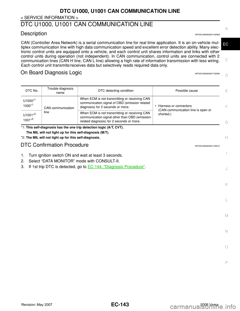
On Board Diagnosis LogicINFOID:0000000001702609
*1: This self-diagnosis has the one trip detection logic (A/T, CVT).
The MIL will not light up for this self-diagnosis (M/T).
*2: The MIL will not light up for this self-diagnosis.
DTC Confirmation ProcedureINFOID:0000000001702610
1. Turn ignition switch ON and wait at least 3 seconds.
2. Select “DATA MONITOR” mode with CONSULT-II.
3. If 1st trip DTC is detected, go to EC-144, "
Diagnosis Procedure".
DTC No.Trouble diagnosis
nameDTC detecting condition Possible cause
U1000*
1
1000*1CAN communication
lineWhen ECM is not transmitting or receiving CAN
communication signal of OBD (emission related
diagnosis) for 2 seconds or more.• Harness or connectors
(CAN communication line is open or
shorted.)
U1001*
2
1001*2
When ECM is not transmitting or receiving CAN
communication signal other than OBD (emission-
related diagnosis) for 2 seconds or more.
Page 1218 of 2771
EC-144
< SERVICE INFORMATION >
DTC U1000, U1001 CAN COMMUNICATION LINE
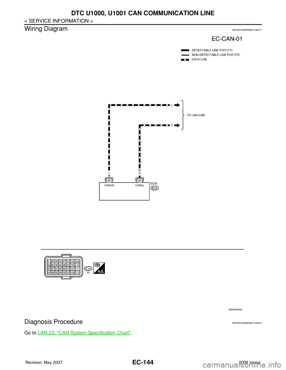
Wiring Diagram
INFOID:0000000001702611
Diagnosis ProcedureINFOID:0000000001702612
Go to LAN-23, "CAN System Specification Chart".
BBWA2626E