2008 NISSAN TIIDA blower
[x] Cancel search: blowerPage 423 of 2771

BCM (BODY CONTROL MODULE)
BCS-7
< SERVICE INFORMATION >
C
D
E
F
G
H
I
J
L
MA
B
BCS
N
O
P
CAN Communication System DescriptionINFOID:0000000001704585
Refer to LAN-6, "System Description".
Panic alarm• Key switch
•KeyfobIPDM E/R
Vehicle security system• All door switches
•Keyfob
• Door lock/unlock switch
• Trunk key cylinder switch (Se-
dan)
• Front door key cylinder switch
LH• IPDM/ER
• Security indicator lamp
Battery saver control• Ignition switch
• Combination switchIPDM E/R
Headlamp Combination switch IPDM E/R
Tail lamp Combination switch IPDM E/R
Front fog lamp Combination switch IPDM E/R
Turn signal lamp Combination switch• Turn signal lamp
• Combination meter
Hazard lamp Hazard switch• Turn signal lamp
• Combination meter
Room lamp timer• Key switch
•Keyfob
• Main power window and door
lock/unlock switch
• Front door switch LH
• All door switchInterior room lamp
Back door switch signal (Hatchback) Back door lock assembly Luggage room lamp
Back door lock signal (Hatchback) Back door lock assembly Back door opener
Trunk lamp switch signalTrunk lamp switch and trunk re-
lease solenoidLuggage room lamp
Trunk lid opener signalTrunk lamp switch and trunk re-
lease solenoidTrunk lid opener
Key warning chime• Key switch
• Front door switch LHCombination meter (warning buzzer)
Light warning chime• Combination switch
• Key switch
• Front door switch LHCombination meter (warning buzzer)
Seat belt warning chime• Seat belt buckle switch LH
• Ignition switchCombination meter (warning buzzer)
Front wiper and washer system• Combination switch
• Ignition switchIPDM E/R
Rear window defogger Rear window defogger switch IPDM E/R
Rear wiper and washer system• Combination switch
• Ignition switchRear wiper motor
A/C switch signal Front air control ECM
Blower fan switch signal Front air control ECM
A/C indicator signal Front air control A/C indicator
Low tire pressure warning system Remote keyless entry receiver Combination meterSystem Input Output
Page 428 of 2771

BCS-12
< SERVICE INFORMATION >
BCM (BODY CONTROL MODULE)
18 VRemote keyless entry
receiver (ground)Output OFF — 0V
19 BRRemote keyless entry
receiver (power sup-
ply)Output OFF Ignition switch OFF
20 GRemote keyless entry
receiver signal (signal)Input OFFStand-by (keyfob buttons re-
leased)
When remote keyless entry
receiver receives signal from
keyfob (keyfob buttons
pressed)
21 P NATS antenna amp.Input/
OutputOFF →
ONIgnition switch (OFF → ON)Just after turning ignition switch
ON: Pointer of tester should
move for approx. 1 second, then
return to battery voltage.
23 RSecurity indicator
lampOutput OFFGoes OFF → illuminates (Ev-
ery 2.4 seconds)Battery voltage → 0V
25 LG NATS antenna amp.Input/
OutputOFF →
ONIgnition switch (OFF → ON)Just after turning ignition switch
ON: Pointer of tester should
move for approx. 1 second, then
return to battery voltage.
26 GR Thermo control amp. Input ON A/C switch ON
27 OCompressor ON sig-
nalInput ONA/C switch OFF 5V
A/C switch ON 0V
28 P Front blower monitor Input ONFront blower motor OFF Battery voltage
Front blower motor ON 0V
29 L Hazard switch Input OFFON 0V
OFF 5V Te r m i n a lWire
colorSignal nameSignal
input/
outputMeasuring condition
Reference value or waveform
(Approx.) Ignition
switchOperation or condition
LIIA1893E
LIIA1894E
LIIA1895E
ZJIA0719J
Page 433 of 2771

BCM (BODY CONTROL MODULE)
BCS-17
< SERVICE INFORMATION >
C
D
E
F
G
H
I
J
L
MA
B
BCS
N
O
P
WORK SUPPORT
Display Item List
CAN Communication Inspection Using CONSULT-III (Self-Diagnosis)INFOID:0000000001704591
1.SELF-DIAGNOSTIC RESULT CHECK
1. Connect CONSULT–III and select “BCM” on “SELECT SYSTEM” screen.
2. Select “BCM” on “SELECT TEST ITEM” screen, and select “SELF-DIAG RESULTS”.
3. Check display content in self-diagnostic results.
Contents displayed
No malfunction>>Inspection End
Malfunction in CAN communication system>>After printing the monitor items, go to “CAN System”. Refer to
LAN-15, "
Trouble Diagnosis Flow Chart".
ConfigurationINFOID:0000000001806223
DESCRIPTION
CONFIGURATION has three functions as follows:
• READ CONFIGURATION is the function to read (extract) vehicle configuration of current BCM.
Blower fan switch sig-
nal
Air conditioner switch
signalAIR CONDITION-
ER×
Intelligent KeyINTELLIGENT
KEY×
Combination switch COMB SW×
NVIS (NATS) IMMU××
Interior lamp battery
saverBATTERY SAV-
ER×××
Back door/Trunk TRUNK××
Theft alarm THEFT ALARM×××
Retained accessory
power controlRETAINED PWR×××
Oil pressure switch SIGNAL BUFFER××
Low tire pressure moni-
torAIR PRESSURE
MONITOR×× × ×
Panic alarm PANIC ALARM× System and itemCONSULT-III dis-
playDiagnostic test mode (Inspection by part)
WORK
SUPPORTSELF−
DIAG RE-
SULTSCAN DIAG
SUPPORT
MNTRDATA
MONITORECU
PA R T
NUMBERAC-
TIVE
TESTCON-
FIGU-
RATION
Item Description
RESET SETTING VALUE Return a value set with WORK SUPPORT of each system to a default value in factory shipment.
CONSULT-III display code Diagnosis item
U1000INITIAL DIAG
TRANSMIT DIAG
ECM
IPDM E/R
METER/M&A
I-KEY
Page 1179 of 2771
![NISSAN TIIDA 2008 Service Repair Manual TROUBLE DIAGNOSIS
EC-105
< SERVICE INFORMATION >
C
D
E
F
G
H
I
J
K
L
MA
EC
N
P O
33 LG Throttle position sensor 1[Ignition switch: ON]
• Engine stopped
• Shift lever: D (A/T, CVT), 1st (M/T)
• A NISSAN TIIDA 2008 Service Repair Manual TROUBLE DIAGNOSIS
EC-105
< SERVICE INFORMATION >
C
D
E
F
G
H
I
J
K
L
MA
EC
N
P O
33 LG Throttle position sensor 1[Ignition switch: ON]
• Engine stopped
• Shift lever: D (A/T, CVT), 1st (M/T)
• A](/manual-img/5/57399/w960_57399-1178.png)
TROUBLE DIAGNOSIS
EC-105
< SERVICE INFORMATION >
C
D
E
F
G
H
I
J
K
L
MA
EC
N
P O
33 LG Throttle position sensor 1[Ignition switch: ON]
• Engine stopped
• Shift lever: D (A/T, CVT), 1st (M/T)
• Accelerator pedal: Fully releasedMore than 0.36V
[Ignition switch: ON]
• Engine stopped
• Shift lever: D (A/T, CVT), 1st (M/T)
• Accelerator pedal: Fully depressedLess than 4.75V
34 O Throttle position sensor 2[Ignition switch: ON]
• Engine stopped
• Shift lever: D (A/T, CVT), 1st (M/T)
• Accelerator pedal: Fully releasedLess than 4.75V
[Ignition switch: ON]
• Engine stopped
• Shift lever: D (A/T, CVT), 1st (M/T)
• Accelerator pedal: Fully depressedMore than 0.36V
36 YSensor ground
(Throttle position sensor)[Engine is running]
•Warm-up condition
• Idle speedApproximately 0V
37 W Knock sensor[Engine is running]
• Idle speedApproximately 2.5V
38 PEngine coolant temperature
sensor[Engine is running]Approximately 0 - 4.8V
Output voltage varies with en-
gine coolant temperature.
40 —Sensor ground
(Knock sensor)[Engine is running]
•Warm-up condition
• Idle speedApproximately 0V
41 GR Refrigerant pressure sensor[Engine is running]
•Warm-up condition
• Both A/C switch and blower fan switch: ON
(Compressor operates.)1.0 - 4.0V
42 VEVAP control system pres-
sure sensor[Ignition switch: ON]Approximately 1.8 - 4.8V
43 PFuel tank temperature sen-
sor[Engine is running]Approximately 0 - 4.8V
Output voltage varies with fuel
tank temperature
44 BSensor ground
(Engine coolant temperature
sensor)[Engine is running]
•Warm-up condition
• Idle speedApproximately 0V
45 G Mass air flow sensor[Engine is running]
•Warm-up condition
• Idle speed0.8 - 1.1V
[Engine is running]
•Warm-up condition
• Engine speed: 2,500 rpm1.4 - 1.7V
46 VIntake air temperature
sensor[Engine is running]Approximately 0 - 4.8V
Output voltage varies with intake
air temperature.
48 BRSensor ground
(Refrigerant pressure sen-
sor)[Engine is running]
•Warm-up condition
• Idle speed
Approximately 0V
49 W A/F sensor 1[Engine is running]
•Warm-up condition
• Engine speed: 2,000 rpmApproximately 1.8V
Output voltage varies with air fuel
ratio. TERMI-
NAL
NO.WIRE
COLORITEM CONDITION DATA (DC Voltage)
Page 1391 of 2771

DTC P0441 EVAP CONTROL SYSTEM
EC-317
< SERVICE INFORMATION >
C
D
E
F
G
H
I
J
K
L
MA
EC
N
P O
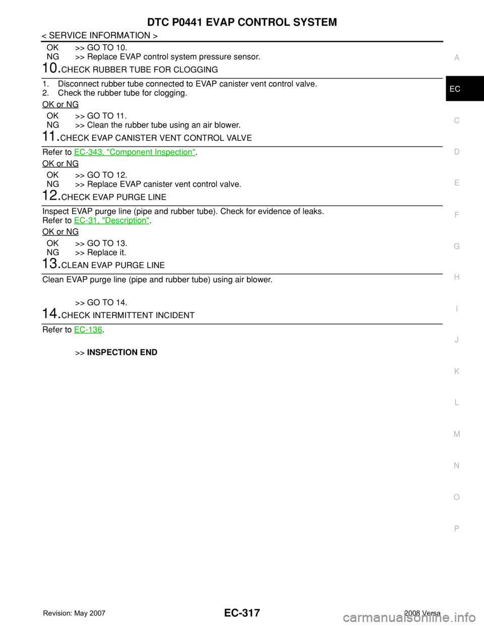
OK >> GO TO 10.
NG >> Replace EVAP control system pressure sensor.
10.CHECK RUBBER TUBE FOR CLOGGING
1. Disconnect rubber tube connected to EVAP canister vent control valve.
2. Check the rubber tube for clogging.
OK or NG
OK >> GO TO 11.
NG >> Clean the rubber tube using an air blower.
11 .CHECK EVAP CANISTER VENT CONTROL VALVE
Refer to EC-343, "
Component Inspection".
OK or NG
OK >> GO TO 12.
NG >> Replace EVAP canister vent control valve.
12.CHECK EVAP PURGE LINE
Inspect EVAP purge line (pipe and rubber tube). Check for evidence of leaks.
Refer to EC-31, "
Description".
OK or NG
OK >> GO TO 13.
NG >> Replace it.
13.CLEAN EVAP PURGE LINE
Clean EVAP purge line (pipe and rubber tube) using air blower.
>> GO TO 14.
14.CHECK INTERMITTENT INCIDENT
Refer to EC-136
.
>>INSPECTION END
Page 1394 of 2771

EC-320
< SERVICE INFORMATION >
DTC P0442 EVAP CONTROL SYSTEM
Diagnosis Procedure
INFOID:0000000001702827
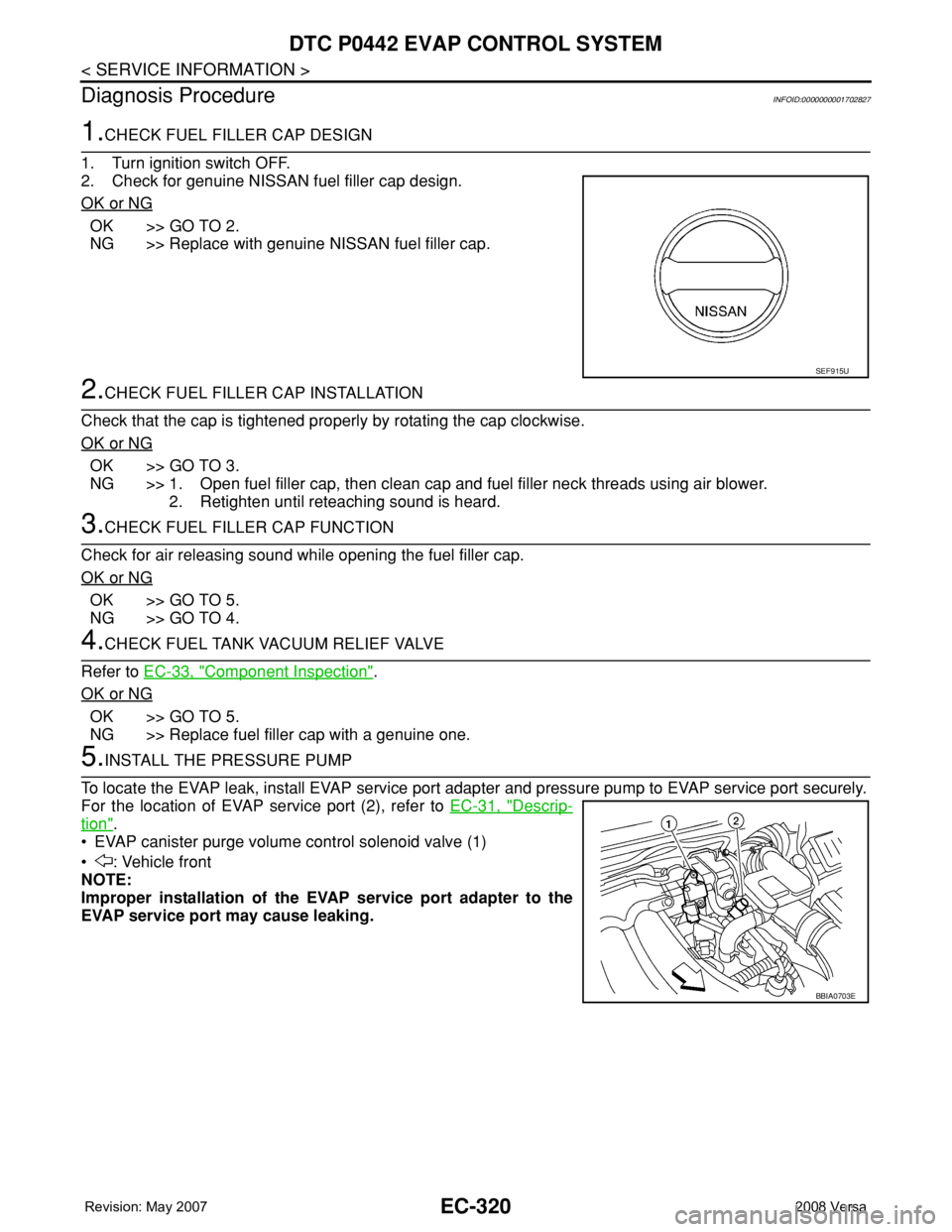
1.CHECK FUEL FILLER CAP DESIGN
1. Turn ignition switch OFF.
2. Check for genuine NISSAN fuel filler cap design.
OK or NG
OK >> GO TO 2.
NG >> Replace with genuine NISSAN fuel filler cap.
2.CHECK FUEL FILLER CAP INSTALLATION
Check that the cap is tightened properly by rotating the cap clockwise.
OK or NG
OK >> GO TO 3.
NG >> 1. Open fuel filler cap, then clean cap and fuel filler neck threads using air blower.
2. Retighten until reteaching sound is heard.
3.CHECK FUEL FILLER CAP FUNCTION
Check for air releasing sound while opening the fuel filler cap.
OK or NG
OK >> GO TO 5.
NG >> GO TO 4.
4.CHECK FUEL TANK VACUUM RELIEF VALVE
Refer to EC-33, "
Component Inspection".
OK or NG
OK >> GO TO 5.
NG >> Replace fuel filler cap with a genuine one.
5.INSTALL THE PRESSURE PUMP
To locate the EVAP leak, install EVAP service port adapter and pressure pump to EVAP service port securely.
For the location of EVAP service port (2), refer to EC-31, "
Descrip-
tion".
• EVAP canister purge volume control solenoid valve (1)
• : Vehicle front
NOTE:
Improper installation of the EVAP service port adapter to the
EVAP service port may cause leaking.
SEF915U
BBIA0703E
Page 1398 of 2771

EC-324
< SERVICE INFORMATION >
DTC P0442 EVAP CONTROL SYSTEM
Clean EVAP purge line (pipe and rubber tube) using air blower.
>> GO TO 20.
20.CHECK EVAP/ORVR LINE
Check EVAP/ORVR line between EVAP canister and fuel tank for clogging, kink, looseness and improper con-
nection. For location, refer to EC-38
.
OK or NG
OK >> GO TO 21.
NG >> Repair or replace hoses and tubes.
21.CHECK RECIRCULATION LINE
Check recirculation line between filler neck tube and fuel tank for clogging, kink, cracks, looseness and
improper connection.
OK or NG
OK >> GO TO 22.
NG >> Repair or replace hoses, tubes or filler neck tube.
22.CHECK REFUELING EVAP VAPOR CUT VALVE
Refer to EC-40, "
Component Inspection".
OK or NG
OK >> GO TO 23.
NG >> Replace refueling EVAP vapor cut valve with fuel tank.
23.CHECK FUEL LEVEL SENSOR
Refer to FL-5
.
OK or NG
OK >> GO TO 24.
NG >> Replace fuel level sensor unit.
24.CHECK INTERMITTENT INCIDENT
Refer to EC-136
.
>>INSPECTION END
Page 1404 of 2771

EC-330
< SERVICE INFORMATION >
DTC P0443 EVAP CANISTER PURGE VOLUME CONTROL SOLENOID VALVE
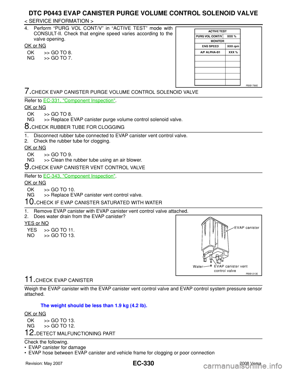
4. Perform “PURG VOL CONT/V” in “ACTIVE TEST” mode with
CONSULT-II. Check that engine speed varies according to the
valve opening.
OK or NG
OK >> GO TO 8.
NG >> GO TO 7.
7.CHECK EVAP CANISTER PURGE VOLUME CONTROL SOLENOID VALVE
Refer to EC-331, "
Component Inspection".
OK or NG
OK >> GO TO 8.
NG >> Replace EVAP canister purge volume control solenoid valve.
8.CHECK RUBBER TUBE FOR CLOGGING
1. Disconnect rubber tube connected to EVAP canister vent control valve.
2. Check the rubber tube for clogging.
OK or NG
OK >> GO TO 9.
NG >> Clean the rubber tube using an air blower.
9.CHECK EVAP CANISTER VENT CONTROL VALVE
Refer to EC-343, "
Component Inspection".
OK or NG
OK >> GO TO 10.
NG >> Replace EVAP canister vent control valve.
10.CHECK IF EVAP CANISTER SATURATED WITH WATER
1. Remove EVAP canister with EVAP canister vent control valve attached.
2. Does water drain from the EVAP canister?
YES or NO
YES >> GO TO 11.
NO >> GO TO 13.
11 .CHECK EVAP CANISTER
Weigh the EVAP canister with the EVAP canister vent control valve and EVAP control system pressure sensor
attached.
OK or NG
OK >> GO TO 13.
NG >> GO TO 12.
12.DETECT MALFUNCTIONING PART
Check the following.
• EVAP canister for damage
• EVAP hose between EVAP canister and vehicle frame for clogging or poor connection
PBIB1786E
PBIB1213E
The weight should be less than 1.9 kg (4.2 lb).