2008 NISSAN TIIDA blower fan
[x] Cancel search: blower fanPage 423 of 2771

BCS-7
< SERVICE INFORMATION >
C
D
E
F
G
H
I
J
L
MA
B
BCS
N
O
P
CAN Communication System DescriptionINFOID:0000000001704585
Refer to LAN-6, \"System Description\".
Panic")
BCM (BODY CONTROL MODULE)
BCS-7
< SERVICE INFORMATION >
C
D
E
F
G
H
I
J
L
MA
B
BCS
N
O
P
CAN Communication System DescriptionINFOID:0000000001704585
Refer to LAN-6, "System Description".
Panic alarm• Key switch
•KeyfobIPDM E/R
Vehicle security system• All door switches
•Keyfob
• Door lock/unlock switch
• Trunk key cylinder switch (Se-
dan)
• Front door key cylinder switch
LH• IPDM/ER
• Security indicator lamp
Battery saver control• Ignition switch
• Combination switchIPDM E/R
Headlamp Combination switch IPDM E/R
Tail lamp Combination switch IPDM E/R
Front fog lamp Combination switch IPDM E/R
Turn signal lamp Combination switch• Turn signal lamp
• Combination meter
Hazard lamp Hazard switch• Turn signal lamp
• Combination meter
Room lamp timer• Key switch
•Keyfob
• Main power window and door
lock/unlock switch
• Front door switch LH
• All door switchInterior room lamp
Back door switch signal (Hatchback) Back door lock assembly Luggage room lamp
Back door lock signal (Hatchback) Back door lock assembly Back door opener
Trunk lamp switch signalTrunk lamp switch and trunk re-
lease solenoidLuggage room lamp
Trunk lid opener signalTrunk lamp switch and trunk re-
lease solenoidTrunk lid opener
Key warning chime• Key switch
• Front door switch LHCombination meter (warning buzzer)
Light warning chime• Combination switch
• Key switch
• Front door switch LHCombination meter (warning buzzer)
Seat belt warning chime• Seat belt buckle switch LH
• Ignition switchCombination meter (warning buzzer)
Front wiper and washer system• Combination switch
• Ignition switchIPDM E/R
Rear window defogger Rear window defogger switch IPDM E/R
Rear wiper and washer system• Combination switch
• Ignition switchRear wiper motor
A/C switch signal Front air control ECM
Blower fan switch signal Front air control ECM
A/C indicator signal Front air control A/C indicator
Low tire pressure warning system Remote keyless entry receiver Combination meterSystem Input Output
Page 433 of 2771

BCS-17
< SERVICE INFORMATION >
C
D
E
F
G
H
I
J
L
MA
B
BCS
N
O
P
WORK SUPPORT
Display Item List
CAN Communication Inspection Using CONSULT-III (Self-Diagnosis)INFOID:000000000")
BCM (BODY CONTROL MODULE)
BCS-17
< SERVICE INFORMATION >
C
D
E
F
G
H
I
J
L
MA
B
BCS
N
O
P
WORK SUPPORT
Display Item List
CAN Communication Inspection Using CONSULT-III (Self-Diagnosis)INFOID:0000000001704591
1.SELF-DIAGNOSTIC RESULT CHECK
1. Connect CONSULT–III and select “BCM” on “SELECT SYSTEM” screen.
2. Select “BCM” on “SELECT TEST ITEM” screen, and select “SELF-DIAG RESULTS”.
3. Check display content in self-diagnostic results.
Contents displayed
No malfunction>>Inspection End
Malfunction in CAN communication system>>After printing the monitor items, go to “CAN System”. Refer to
LAN-15, "
Trouble Diagnosis Flow Chart".
ConfigurationINFOID:0000000001806223
DESCRIPTION
CONFIGURATION has three functions as follows:
• READ CONFIGURATION is the function to read (extract) vehicle configuration of current BCM.
Blower fan switch sig-
nal
Air conditioner switch
signalAIR CONDITION-
ER×
Intelligent KeyINTELLIGENT
KEY×
Combination switch COMB SW×
NVIS (NATS) IMMU××
Interior lamp battery
saverBATTERY SAV-
ER×××
Back door/Trunk TRUNK××
Theft alarm THEFT ALARM×××
Retained accessory
power controlRETAINED PWR×××
Oil pressure switch SIGNAL BUFFER××
Low tire pressure moni-
torAIR PRESSURE
MONITOR×× × ×
Panic alarm PANIC ALARM× System and itemCONSULT-III dis-
playDiagnostic test mode (Inspection by part)
WORK
SUPPORTSELF−
DIAG RE-
SULTSCAN DIAG
SUPPORT
MNTRDATA
MONITORECU
PA R T
NUMBERAC-
TIVE
TESTCON-
FIGU-
RATION
Item Description
RESET SETTING VALUE Return a value set with WORK SUPPORT of each system to a default value in factory shipment.
CONSULT-III display code Diagnosis item
U1000INITIAL DIAG
TRANSMIT DIAG
ECM
IPDM E/R
METER/M&A
I-KEY
Page 1179 of 2771
![NISSAN TIIDA 2008 Service Repair Manual TROUBLE DIAGNOSIS
EC-105
< SERVICE INFORMATION >
C
D
E
F
G
H
I
J
K
L
MA
EC
N
P O
33 LG Throttle position sensor 1[Ignition switch: ON]
• Engine stopped
• Shift lever: D (A/T, CVT), 1st (M/T)
• A](/manual-img/5/57399/w960_57399-1178.png "NISSAN TIIDA 2008 Service Repair Manual TROUBLE DIAGNOSIS
EC-105
< SERVICE INFORMATION >
C
D
E
F
G
H
I
J
K
L
MA
EC
N
P O
33 LG Throttle position sensor 1[Ignition switch: ON]
• Engine stopped
• Shift lever: D (A/T, CVT), 1st (M/T)
• A")
TROUBLE DIAGNOSIS
EC-105
< SERVICE INFORMATION >
C
D
E
F
G
H
I
J
K
L
MA
EC
N
P O
33 LG Throttle position sensor 1[Ignition switch: ON]
• Engine stopped
• Shift lever: D (A/T, CVT), 1st (M/T)
• Accelerator pedal: Fully releasedMore than 0.36V
[Ignition switch: ON]
• Engine stopped
• Shift lever: D (A/T, CVT), 1st (M/T)
• Accelerator pedal: Fully depressedLess than 4.75V
34 O Throttle position sensor 2[Ignition switch: ON]
• Engine stopped
• Shift lever: D (A/T, CVT), 1st (M/T)
• Accelerator pedal: Fully releasedLess than 4.75V
[Ignition switch: ON]
• Engine stopped
• Shift lever: D (A/T, CVT), 1st (M/T)
• Accelerator pedal: Fully depressedMore than 0.36V
36 YSensor ground
(Throttle position sensor)[Engine is running]
•Warm-up condition
• Idle speedApproximately 0V
37 W Knock sensor[Engine is running]
• Idle speedApproximately 2.5V
38 PEngine coolant temperature
sensor[Engine is running]Approximately 0 - 4.8V
Output voltage varies with en-
gine coolant temperature.
40 —Sensor ground
(Knock sensor)[Engine is running]
•Warm-up condition
• Idle speedApproximately 0V
41 GR Refrigerant pressure sensor[Engine is running]
•Warm-up condition
• Both A/C switch and blower fan switch: ON
(Compressor operates.)1.0 - 4.0V
42 VEVAP control system pres-
sure sensor[Ignition switch: ON]Approximately 1.8 - 4.8V
43 PFuel tank temperature sen-
sor[Engine is running]Approximately 0 - 4.8V
Output voltage varies with fuel
tank temperature
44 BSensor ground
(Engine coolant temperature
sensor)[Engine is running]
•Warm-up condition
• Idle speedApproximately 0V
45 G Mass air flow sensor[Engine is running]
•Warm-up condition
• Idle speed0.8 - 1.1V
[Engine is running]
•Warm-up condition
• Engine speed: 2,500 rpm1.4 - 1.7V
46 VIntake air temperature
sensor[Engine is running]Approximately 0 - 4.8V
Output voltage varies with intake
air temperature.
48 BRSensor ground
(Refrigerant pressure sen-
sor)[Engine is running]
•Warm-up condition
• Idle speed
Approximately 0V
49 W A/F sensor 1[Engine is running]
•Warm-up condition
• Engine speed: 2,000 rpmApproximately 1.8V
Output voltage varies with air fuel
ratio. TERMI-
NAL
NO.WIRE
COLORITEM CONDITION DATA (DC Voltage)
Page 1488 of 2771

EC-414
< SERVICE INFORMATION >
DTC P1217 ENGINE OVER TEMPERATURE
Never remove the radiator cap when the engine is hot. Serious burns could be caused by high pres-
sure fluid escaping from the reservoir tank or the radiator.
Wrap a thick cloth around cap. Carefully remove the cap by turning it a quarter turn to allow built-up
pressure to escape. Then turn the cap all the way off.
WITH CONSULT-II
1. Check the coolant level in the reservoir tank and radiator.
Allow engine to cool before checking coolant level.
If the coolant level in the reservoir tank and/or radiator is below
the proper range, skip the following steps and go to EC-417,
"Diagnosis Procedure" or EC-417, "Diagnosis Procedure".
2. Confirm whether customer filled the coolant or not. If customer
filled the coolant, skip the following steps and go to EC-417,
"Diagnosis Procedure" or EC-417, "Diagnosis Procedure".
3. Turn ignition switch ON.
4. Perform “COOLING FAN” in “ACTIVE TEST” mode with CON-
SULT-II.
5. If the results are NG, go to EC-417, "
Diagnosis Procedure" or
EC-417, "
Diagnosis Procedure".
WITH GST
Models with A/C
1. Check the coolant level in the reservoir tank and radiator.
Allow engine to cool before checking coolant level.
If the coolant level in the reservoir tank and/or radiator is below
the proper range, skip the following steps and go to EC-417,
"Diagnosis Procedure".
2. Confirm whether customer filled the coolant or not. If customer
filled the coolant, skip the following steps and go to EC-417,
"Diagnosis Procedure".
3. Start engine.
CAUTION:
Be careful not to overheat engine.
4. Set temperature control switch to full cold position.
5. Turn air conditioner switch ON.
6. Turn blower fan switch ON.
7. Run engine at idle for a few minutes with air conditioner operating.
CAUTION:
Be careful not to overheat engine.
SEF621W
SEF646X
SEF621W
Page 1489 of 2771
DTC P1217 ENGINE OVER TEMPERATURE
EC-415
< SERVICE INFORMATION >
C
D
E
F
G
H
I
J
K
L
MA
EC
N
P O
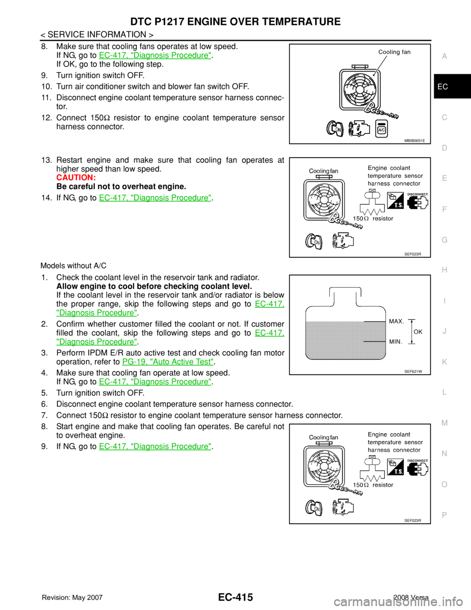
8. Make sure that cooling fans operates at low speed.
If NG, go to EC-417, "
Diagnosis Procedure".
If OK, go to the following step.
9. Turn ignition switch OFF.
10. Turn air conditioner switch and blower fan switch OFF.
11. Disconnect engine coolant temperature sensor harness connec-
tor.
12. Connect 150Ω resistor to engine coolant temperature sensor
harness connector.
13. Restart engine and make sure that cooling fan operates at
higher speed than low speed.
CAUTION:
Be careful not to overheat engine.
14. If NG, go to EC-417, "
Diagnosis Procedure".
Models without A/C
1. Check the coolant level in the reservoir tank and radiator.
Allow engine to cool before checking coolant level.
If the coolant level in the reservoir tank and/or radiator is below
the proper range, skip the following steps and go to EC-417,
"Diagnosis Procedure".
2. Confirm whether customer filled the coolant or not. If customer
filled the coolant, skip the following steps and go to EC-417,
"Diagnosis Procedure".
3. Perform IPDM E/R auto active test and check cooling fan motor
operation, refer to PG-19, "
Auto Active Test".
4. Make sure that cooling fan operate at low speed.
If NG, go to EC-417, "
Diagnosis Procedure".
5. Turn ignition switch OFF.
6. Disconnect engine coolant temperature sensor harness connector.
7. Connect 150Ω resistor to engine coolant temperature sensor harness connector.
8. Start engine and make that cooling fan operates. Be careful not
to overheat engine.
9. If NG, go to EC-417, "
Diagnosis Procedure".
MBIB0651E
SEF023R
SEF621W
SEF023R
Page 1492 of 2771

EC-418
< SERVICE INFORMATION >
DTC P1217 ENGINE OVER TEMPERATURE
No >> GO TO 4.
2.CHECK COOLING FAN LOW SPEED OPERATION
With CONSULT-II
1. Turn ignition switch ON.
2. Perform “COOLING FAN” in “ACTIVE TEST” mode with CON-
SULT-II and touch “LOW” on the CONSULT-II screen.
3. Make sure that cooling fan operate at low speed.
OK or NG
OK >> GO TO 3.
NG >> Check cooling fan control circuit. (Go to "PROCEDURE
A".)
3.CHECK COOLING FAN HIGH SPEED OPERATION
With CONSULT-II
1. Touch “HIGH” on the CONSULT-II screen.
2. Make sure that cooling fan operate at higher speed than low
speed.
OK or NG
OK >> GO TO 6.
NG >> Check cooling fan control circuit. (Go to "PROCEDURE
A".)
4.CHECK COOLING FAN LOW SPEED OPERATION
Without CONSULT-II
1. Start engine and let it idle.
2. Turn air conditioner switch ON.
3. Turn blower fan switch ON.
4. Make sure that cooling fan operate at low speed.
OK or NG
OK >> GO TO 5.
NG >> Check cooling fan low speed control circuit. (Go to
"PROCEDURE A".)
5.CHECK COOLING FAN HIGH SPEED OPERATION
Without CONSULT-II
1. Turn ignition switch OFF.
2. Turn air conditioner switch and blower fan switch OFF.
3. Disconnect engine coolant temperature sensor harness connector.
4. Connect 150Ω resistor to engine coolant temperature sensor harness connector.
SEF784Z
SEF785Z
MBIB0651E
Page 1617 of 2771

REFRIGERANT PRESSURE SENSOR
EC-543
< SERVICE INFORMATION >
C
D
E
F
G
H
I
J
K
L
MA
EC
N
P O
Diagnosis ProcedureINFOID:0000000001703078
1.CHECK REFRIGERANT PRESSURE SENSOR OVERALL FUNCTION
1. Start engine and warm it up to normal operating temperature.
2. Turn A/C switch and blower fan switch ON.
3. Check voltage between ECM terminal 41 and ground with CON-
SULT-II or tester.
OK or NG
OK >>INSPECTION END
NG >> GO TO 2.
2.CHECK GROUND CONNECTIONS
1. Turn A/C switch and blower fan switch OFF.
2. Stop engine and turn ignition switch OFF.
3. Loosen and retighten ground screw on the body.
Refer to EC-142, "
Ground Inspection".
OK or NG
OK >> GO TO 3.
NG >> Repair or replace ground connections.
3.CHECK REFRIGERANT PRESSURE SENSOR POWER SUPPLY CIRCUIT
TERMI-
NAL
NO.WIRE
COLORITEM CONDITION DATA (DC Voltage)
41 GR Refrigerant pressure sensor[Engine is running]
•Warm-up condition
• Both A/C switch and blower fan switch: ON
(Compressor operates)1.0 - 4.0V
48 BRSensor ground
(Refrigerant pressure sensor)[Engine is running]
•Warm-up condition
• Idle speedApproximately 0V
74 WSensor power supply
(Refrigerant pressure sensor)[Ignition switch: ON]Approximately 5V
Voltage: 1.0 - 4.0V
PBIA9574J
:Vehicle front
1. Body ground E24 2. Engine ground F9 3. Engine ground F16
4. Body ground E15
BBIA0698E
Page 2015 of 2771
![NISSAN TIIDA 2008 Service Repair Manual LAN-24
< FUNCTION DIAGNOSIS >[CAN]
CAN COMMUNICATION SYSTEM
Engine coolant temperature signal T R
Engine speed signal T R R
Engine status signal T R
Fuel consumption monitor signal T R
Malfunction ind](/manual-img/5/57399/w960_57399-2014.png "NISSAN TIIDA 2008 Service Repair Manual LAN-24
< FUNCTION DIAGNOSIS >[CAN]
CAN COMMUNICATION SYSTEM
Engine coolant temperature signal T R
Engine speed signal T R R
Engine status signal T R
Fuel consumption monitor signal T R
Malfunction ind")
LAN-24
< FUNCTION DIAGNOSIS >[CAN]
CAN COMMUNICATION SYSTEM
Engine coolant temperature signal T R
Engine speed signal T R R
Engine status signal T R
Fuel consumption monitor signal T R
Malfunction indicator lamp signal T R
Wide open throttle position signal T R R
A/C switch signal R T
Blower fan motor switch signal R T
Buzzer output signalTR
TR
Day time running light request signal
*3TR R
Door lock/unlock status signal T R
Door switch signal T R R R
Front wiper request signal T R
High beam request signal T R R
Horn chirp signal T R
Ignition switch signal T R
Low beam request signal T R
Position lights request signal T R R
Rear window defogger switch signal T R
Sleep/wake up signalRT
TRR R
Theft warning horn request signal T R
Tire pressure signal
*4TR
Trunk open/close status signal T R
Turn indicator signal T R
EPS operation signal R T
EPS warning lamp signal T R
Door lock/unlock/trunk open request signal R T
Hazard request signal R T
Ignition knob switch signal R T
KEY warning lamp signal T R
LOCK warning lamp signal T R
Panic alarm request signal R T
Fuel level sensor signal R T
Overdrive control switch signal T R R
P/N range signal T R
Stop lamp switch signal T R R
Vehicle speed signalRRR T
RRRT R
R
*5R*5T*5
ABS warning lamp signal R TSignal name/Connecting unit
ECM
BCM
EPS
I-KEY
M&A
ABS
TCM
*1
TCM
*2
IPDM-E