2008 NISSAN TIIDA meter
[x] Cancel search: meterPage 644 of 2771
BL-210
< SERVICE INFORMATION >
NATS (NISSAN ANTI-THEFT SYSTEM)
NATS (NISSAN ANTI-THEFT SYSTEM)
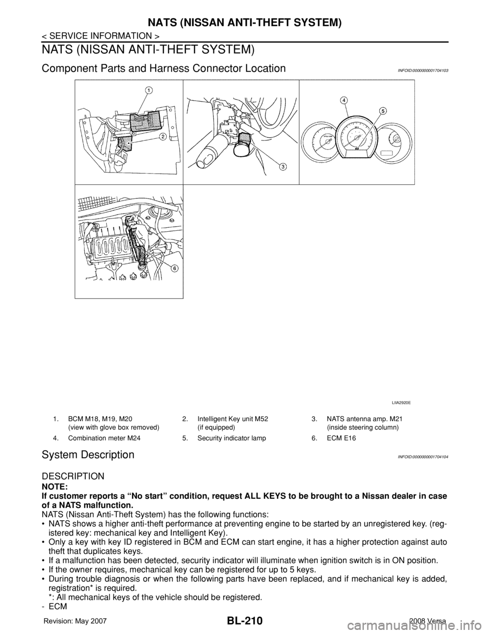
Component Parts and Harness Connector LocationINFOID:0000000001704103
System DescriptionINFOID:0000000001704104
DESCRIPTION
NOTE:
If customer reports a “No start” condition, request ALL KEYS to be brought to a Nissan dealer in case
of a NATS malfunction.
NATS (Nissan Anti-Theft System) has the following functions:
• NATS shows a higher anti-theft performance at preventing engine to be started by an unregistered key. (reg-
istered key: mechanical key and Intelligent Key).
• Only a key with key ID registered in BCM and ECM can start engine, it has a higher protection against auto
theft that duplicates keys.
• If a malfunction has been detected, security indicator will illuminate when ignition switch is in ON position.
• If the owner requires, mechanical key can be registered for up to 5 keys.
• During trouble diagnosis or when the following parts have been replaced, and if mechanical key is added,
registration* is required.
*: All mechanical keys of the vehicle should be registered.
-ECM
LIIA2920E
1. BCM M18, M19, M20
(view with glove box removed)2. Intelligent Key unit M52
(if equipped)3. NATS antenna amp. M21
(inside steering column)
4. Combination meter M24 5. Security indicator lamp 6. ECM E16
Page 649 of 2771
NATS (NISSAN ANTI-THEFT SYSTEM)
BL-215
< SERVICE INFORMATION >
C
D
E
F
G
H
J
K
L
MA
B
BL
N
O
P
Trouble Diagnosis ProcedureINFOID:0000000001704110
PRELIMINARY CHECK
1.GET SYMPTOMS
Listen to customer complaints request. (Get symptoms)
NOTE:
If customer reports a “No start” condition, request all Intelligent Keys to be brought to the dealer in case of
Intelligent Key system malfunction.
Intelligent Key or mechanical key service request>> For further information, refer to CONSULT-III operation
manual.
Malfunctions>>GO TO 2.
2.START ENGINE WITH INTELLIGENT KEY (IF EQUIPPED)
Check if the engine could be started by all registered Intelligent Keys.
The engine cannot be started by some Intelligent Keys>>Intelligent Key is low battery or malfunction. Refer
to BL-142, "
Intelligent Key Battery Replacement" .
The engine cannot be started by all Intelligent Keys>>GO TO 3.
The engine can be started by all Intelligent Keys>>GO TO 4.
3.CHECK “KEY” WARNING LAMP ILLUMINATION
When pushing the ignition switch, check if “KEY” warning lamp in combination meter illuminates.
KEY warning lamp illuminates green>>GO TO BL-103, "
Trouble Diagnosis Symptom Chart" .
KEY warning lamp illuminates red>>GO TO BL-103, "
Trouble Diagnosis Symptom Chart" .
Does not illuminate>>GO TO BL-103, "
Trouble Diagnosis Symptom Chart" .
4.START ENGINE WITH MECHANICAL KEY
Check if the engine could be started by all registered mechanical keys.
The engine can not be started by some mechanical keys>>Register mechanical key. Refer to CONSULT-III
operation manual.
The engine cannot be started by all mechanical keys>> "WORK FLOW" .
The engine can be started by all mechanical keys>>GO TO 5.
5.PERFORM SELF-DIAGNOSIS
1. Turn ignition switch to ON by carrying the Intelligent Key.
2. Perform self-diagnosis of Intelligent Key system with CONSULT-III.
Malfunction is detected>>GO TO BL-101, "
CONSULT-III Application Item" .
No malfunction is detected>>GO TO BL-99, "
Trouble Diagnosis Procedure" .
WORK FLOW
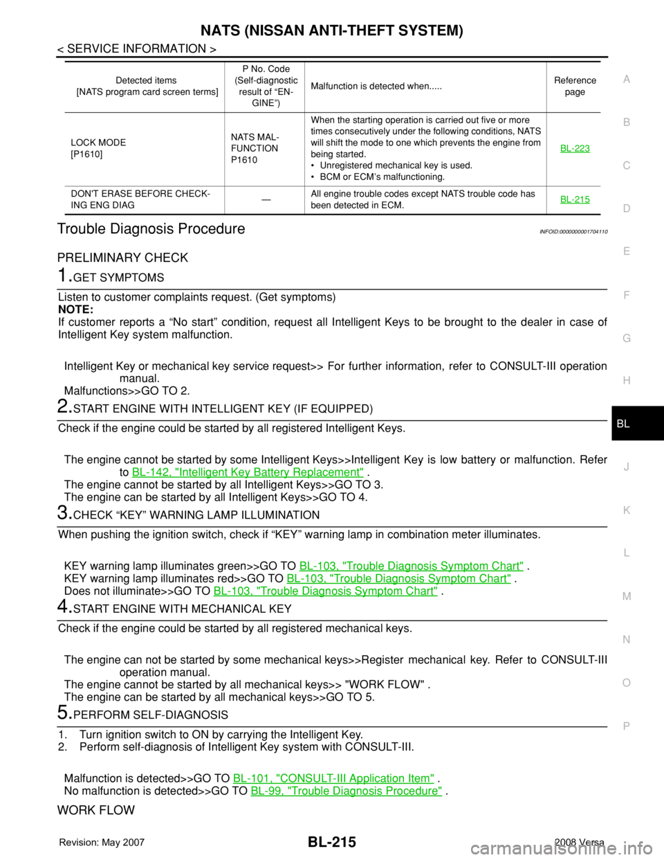
LOCK MODE
[P1610]NATS MAL-
FUNCTION
P1610When the starting operation is carried out five or more
times consecutively under the following conditions, NATS
will shift the mode to one which prevents the engine from
being started.
• Unregistered mechanical key is used.
• BCM or ECM’s malfunctioning.BL-223
DON'T ERASE BEFORE CHECK-
ING ENG DIAG—All engine trouble codes except NATS trouble code has
been detected in ECM.BL-215
Detected items
[NATS program card screen terms]P No. Code
(Self-diagnostic
result of “EN-
GINE”)Malfunction is detected when.....Reference
page
Page 656 of 2771
BL-222
< SERVICE INFORMATION >
NATS (NISSAN ANTI-THEFT SYSTEM)
“ID DISCORD IMM-ECM”:
Registered ID of BCM is in discord with that of ECM.
Is
“ID DISCORD IMM-ECM” displayed?
Ye s > > G O T O 2 .
No >> GO TO BL-217, "
Trouble Diagnosis" .
2.PERFORM INITIALIZATION WITH CONSULT-III
Perform initialization with CONSULT-III. Re-register all NATS ignition key IDs.
For initialization, refer to “CONSULT-III Operation Manual NATS”.
NOTE:
If the initialization is not completed or malfunctions, CONSULT-III shows message on the screen.
Can the system be initialized?
Yes >> • Start engine. (END)
• (System initialization had not been completed.)
No >> ECM is malfunctioning.
• Replace ECM.
• Perform initialization with CONSULT-III
For initialization, refer to “CONSULT-III Operation Manual NATS”
Diagnosis Procedure 4INFOID:0000000001704115
“COMBINATION METER (SECURITY) DOES NOT LIGHT UP”
1.CHECK FUSE
Check 10A fuse [No.13, located in the fuse block (J/B)]
OK or NG
OK >> GO TO 2.
NG >> Replace fuse.
2.CHECK COMBINATION METER (SECURITY)
1. Install 10A fuse.
2. Start engine and turn ignition switch OFF.
3. Check if the combination meter (security) lights up.
OK or NG
OK >> INSPECTION END.
NG >> GO TO 3.
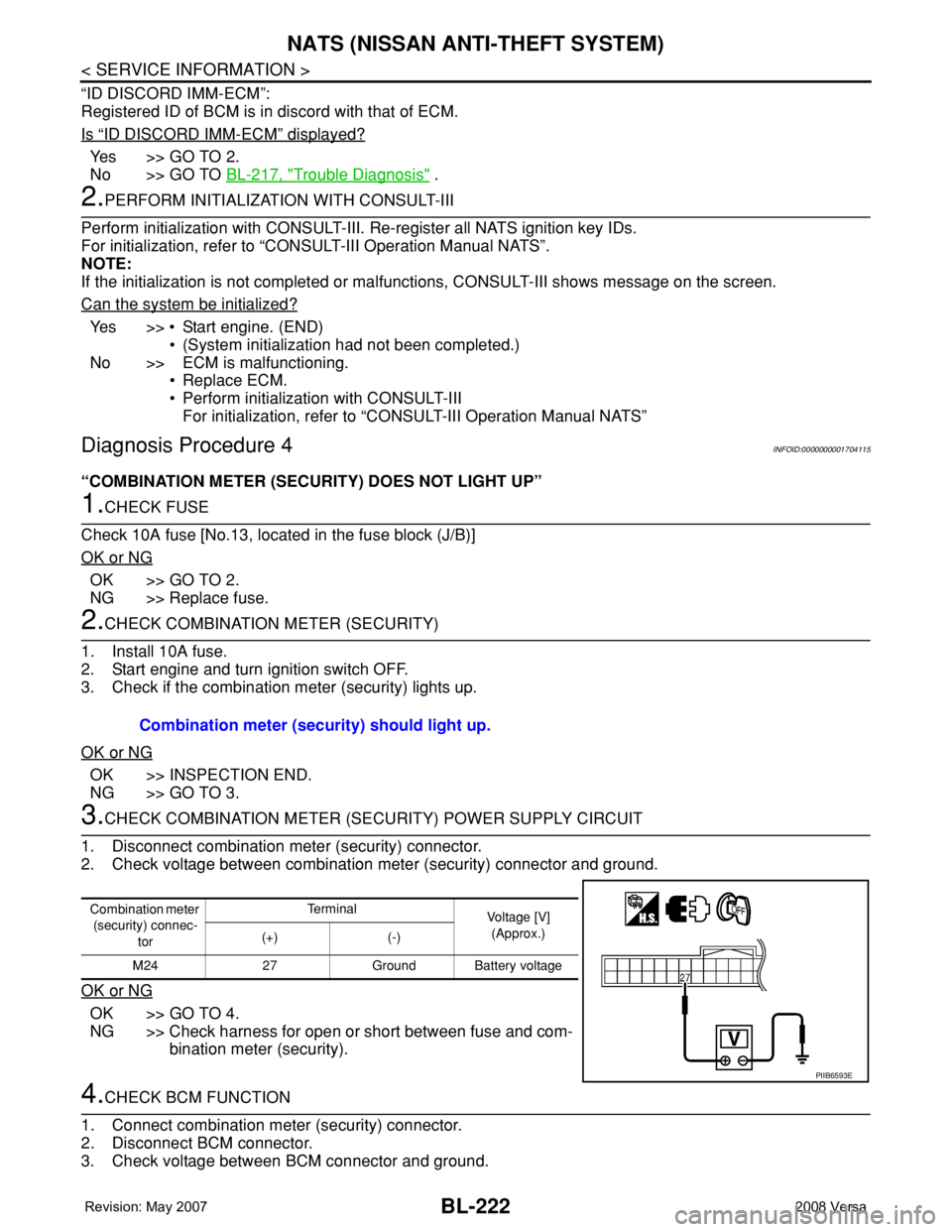
3.CHECK COMBINATION METER (SECURITY) POWER SUPPLY CIRCUIT
1. Disconnect combination meter (security) connector.
2. Check voltage between combination meter (security) connector and ground.
OK or NG
OK >> GO TO 4.
NG >> Check harness for open or short between fuse and com-
bination meter (security).
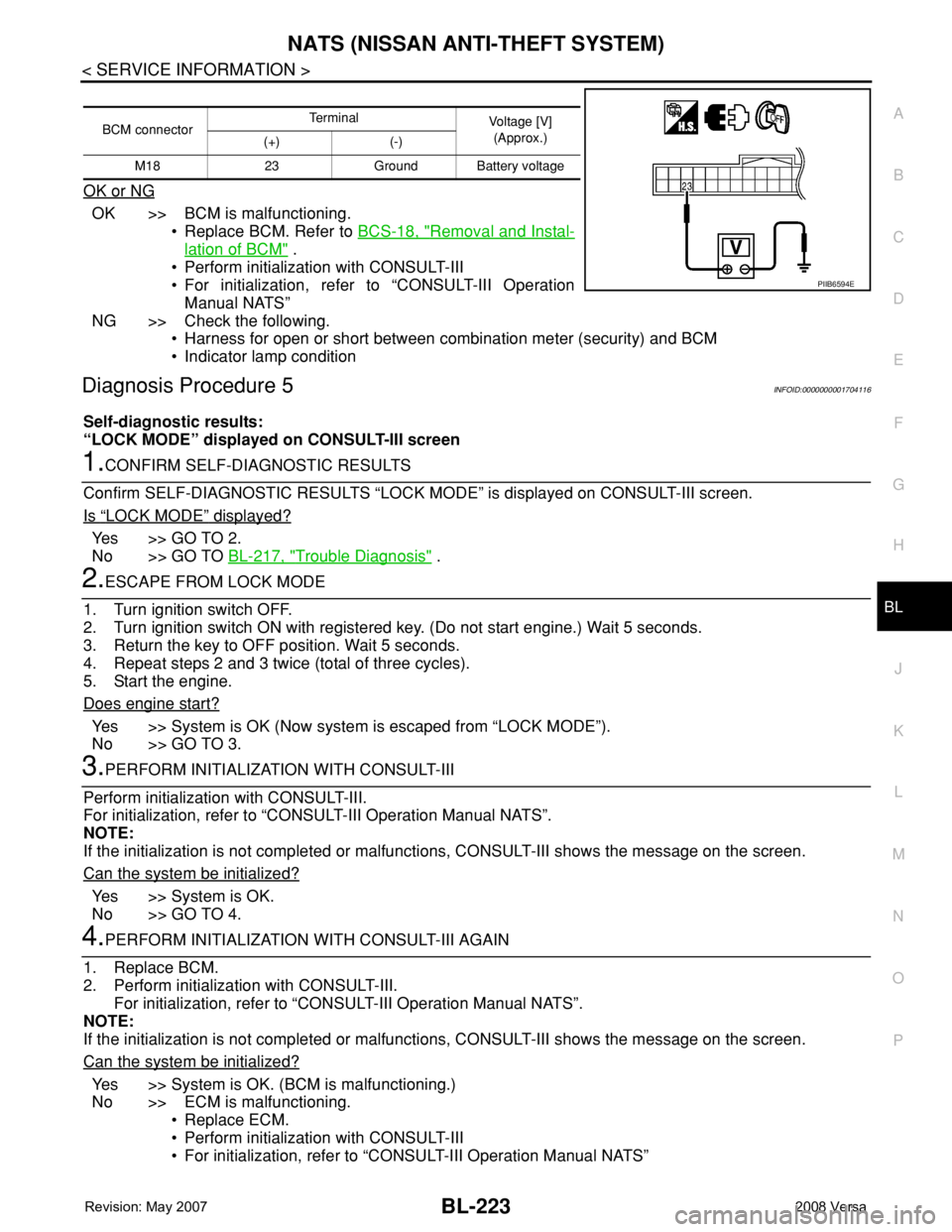
4.CHECK BCM FUNCTION
1. Connect combination meter (security) connector.
2. Disconnect BCM connector.
3. Check voltage between BCM connector and ground. Combination meter (security) should light up.
Combination meter
(security) connec-
torTe r m i n a l
Voltage [V]
(Approx.)
(+) (-)
M24 27 Ground Battery voltage
PIIB6593E
Page 657 of 2771
NATS (NISSAN ANTI-THEFT SYSTEM)
BL-223
< SERVICE INFORMATION >
C
D
E
F
G
H
J
K
L
MA
B
BL
N
O
P
OK or NG
OK >> BCM is malfunctioning.
• Replace BCM. Refer to BCS-18, "
Removal and Instal-
lation of BCM" .
• Perform initialization with CONSULT-III
• For initialization, refer to “CONSULT-III Operation
Manual NATS”
NG >> Check the following.
• Harness for open or short between combination meter (security) and BCM
• Indicator lamp condition
Diagnosis Procedure 5INFOID:0000000001704116
Self-diagnostic results:
“LOCK MODE” displayed on CONSULT-III screen
1.CONFIRM SELF-DIAGNOSTIC RESULTS
Confirm SELF-DIAGNOSTIC RESULTS “LOCK MODE” is displayed on CONSULT-III screen.
Is
“LOCK MODE” displayed?
Yes >> GO TO 2.
No >> GO TO BL-217, "
Trouble Diagnosis" .
2.ESCAPE FROM LOCK MODE
1. Turn ignition switch OFF.
2. Turn ignition switch ON with registered key. (Do not start engine.) Wait 5 seconds.
3. Return the key to OFF position. Wait 5 seconds.
4. Repeat steps 2 and 3 twice (total of three cycles).
5. Start the engine.
Does engine start?
Yes >> System is OK (Now system is escaped from “LOCK MODE”).
No >> GO TO 3.
3.PERFORM INITIALIZATION WITH CONSULT-III
Perform initialization with CONSULT-III.
For initialization, refer to “CONSULT-III Operation Manual NATS”.
NOTE:
If the initialization is not completed or malfunctions, CONSULT-III shows the message on the screen.
Can the system be initialized?
Yes >> System is OK.
No >> GO TO 4.
4.PERFORM INITIALIZATION WITH CONSULT-III AGAIN
1. Replace BCM.
2. Perform initialization with CONSULT-III.
For initialization, refer to “CONSULT-III Operation Manual NATS”.
NOTE:
If the initialization is not completed or malfunctions, CONSULT-III shows the message on the screen.
Can the system be initialized?
Yes >> System is OK. (BCM is malfunctioning.)
No >> ECM is malfunctioning.
• Replace ECM.
• Perform initialization with CONSULT-III
• For initialization, refer to “CONSULT-III Operation Manual NATS”
BCM connectorTerminal
Voltage [V]
(Approx.)
(+) (-)
M18 23 Ground Battery voltage
PIIB6594E
Page 700 of 2771
BL-266
< SERVICE INFORMATION >
BODY REPAIR
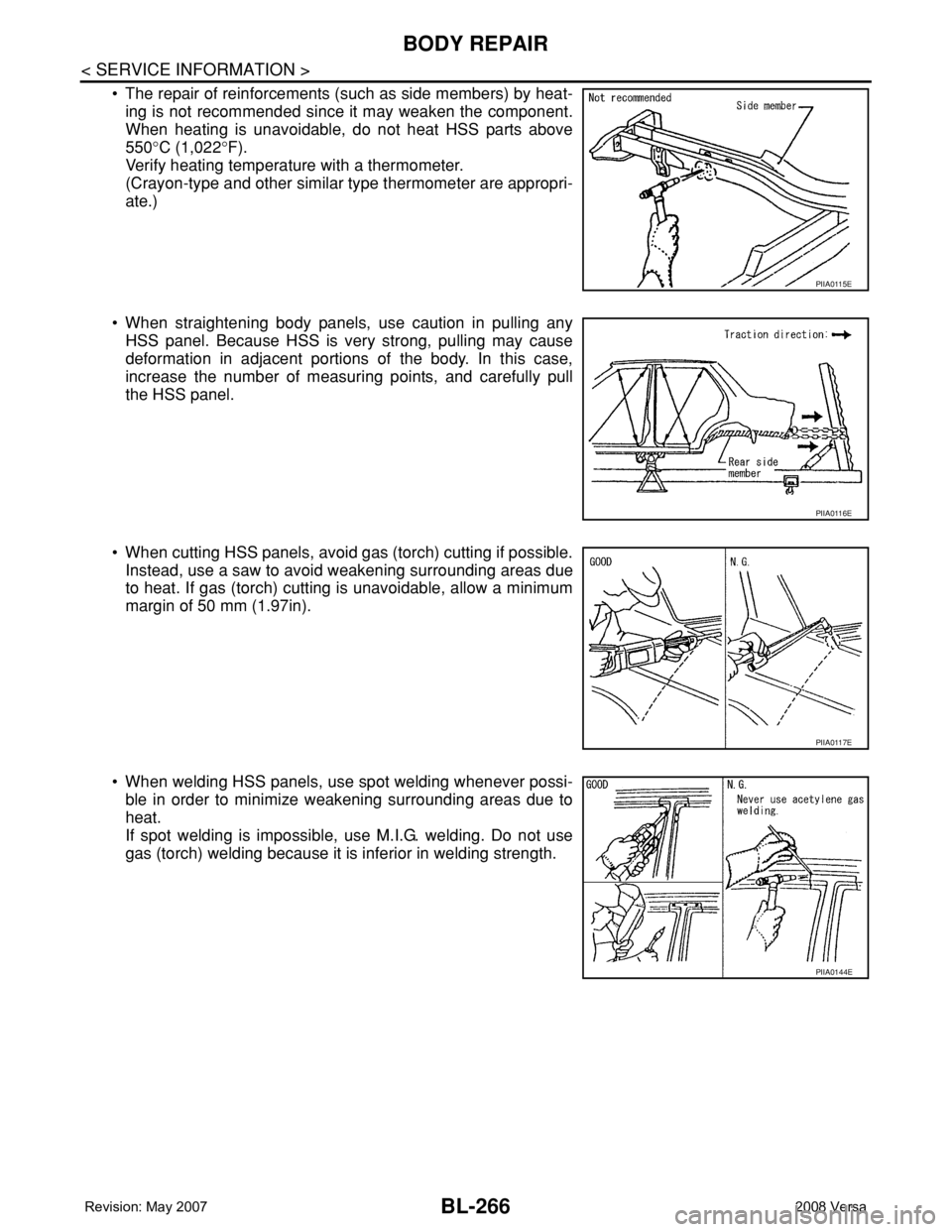
• The repair of reinforcements (such as side members) by heat-
ing is not recommended since it may weaken the component.
When heating is unavoidable, do not heat HSS parts above
550°C (1,022°F).
Verify heating temperature with a thermometer.
(Crayon-type and other similar type thermometer are appropri-
ate.)
• When straightening body panels, use caution in pulling any
HSS panel. Because HSS is very strong, pulling may cause
deformation in adjacent portions of the body. In this case,
increase the number of measuring points, and carefully pull
the HSS panel.
• When cutting HSS panels, avoid gas (torch) cutting if possible.
Instead, use a saw to avoid weakening surrounding areas due
to heat. If gas (torch) cutting is unavoidable, allow a minimum
margin of 50 mm (1.97in).
• When welding HSS panels, use spot welding whenever possi-
ble in order to minimize weakening surrounding areas due to
heat.
If spot welding is impossible, use M.I.G. welding. Do not use
gas (torch) welding because it is inferior in welding strength.
PIIA0115E
PIIA0116E
PIIA0117E
PIIA0144E
Page 701 of 2771
BODY REPAIR
BL-267
< SERVICE INFORMATION >
C
D
E
F
G
H
J
K
L
MA
B
BL
N
O
P
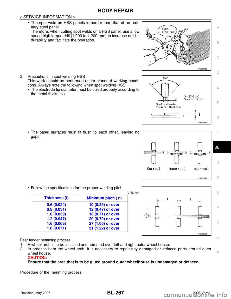
• The spot weld on HSS panels is harder than that of an ordi-
nary steel panel.
Therefore, when cutting spot welds on a HSS panel, use a low
speed high torque drill (1,000 to 1,200 rpm) to increase drill bit
durability and facilitate the operation.
2. Precautions in spot welding HSS
This work should be performed under standard working condi-
tions. Always note the following when spot welding HSS:
• The electrode tip diameter must be sized properly according to
the metal thickness.
• The panel surfaces must fit flush to each other, leaving no
gaps.
• Follow the specifications for the proper welding pitch.
Unit: mm
Rear fender hemming process
1. A wheel arch is to be installed and hemmed over left and right outer wheel house.
2. In order to hem the wheel arch, it is necessary to repair any damaged or defaced parts around outer
wheel house.
CAUTION:
Ensure that the area that is to be glued around outer wheelhouse is undamaged or defaced.
Procedure of the hemming process
PIIA0145E
PIIA0146E
PIIA0147E
Thickness (t)
Minimum pitch ( )
0.6 (0.024)
0.8 (0.031)
1.0 (0.039)
1.2 (0.047)
1.6 (0.063)
1.8 (0.071)10 (0.39) or over
12 (0.47) or over
18 (0.71) or over
20 (0.79) or over
27 (1.06) or over
31 (1.22) or over
PIIA0148E
Page 734 of 2771
PREPARATION
BR-3
< SERVICE INFORMATION >
C
D
E
G
H
I
J
K
L
MA
B
BR
N
O
P
PREPARATION
Commercial Service ToolINFOID:0000000001703777
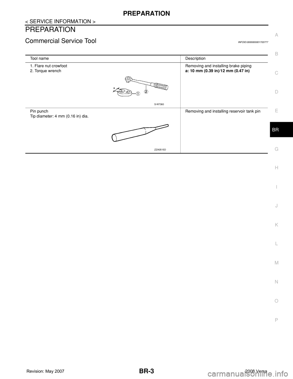
Tool nameDescription
1. Flare nut crowfoot
2. Torque wrenchRemoving and installing brake piping
a: 10 mm (0.39 in)/12 mm (0.47 in)
Pin punch
Tip diameter: 4 mm (0.16 in) dia. Removing and installing reservoir tank pin
S-NT360
ZZA0515D
Page 745 of 2771
BR-14
< SERVICE INFORMATION >
BRAKE MASTER CYLINDER
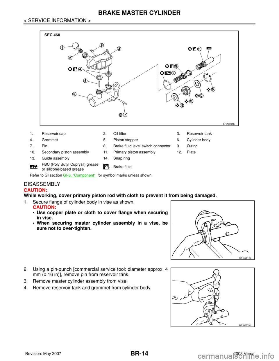
DISASSEMBLY
CAUTION:
While working, cover primary piston rod with cloth to prevent it from being damaged.
1. Secure flange of cylinder body in vise as shown.
CAUTION:
• Use copper plate or cloth to cover flange when securing
in vise.
• When securing master cylinder assembly in a vise, be
sure not to over-tighten.
2. Using a pin-punch [commercial service tool: diameter approx. 4
mm (0.16 in)], remove pin from reservoir tank.
3. Remove master cylinder assembly from vise.
4. Remove reservoir tank and grommet from cylinder body.
1. Reservoir cap 2. Oil filter 3. Reservoir tank
4. Grommet 5. Piston stopper 6. Cylinder body
7. Pin 8. Brake fluid level switch connector 9. O-ring
10. Secondary piston assembly 11. Primary piston assembly 12. Plate
13. Guide assembly 14. Snap ring
:PBC (Poly Butyl Cuprysil) grease
or silicone-based grease:Brake fluid
Refer to GI section GI-8, "
Component" for symbol marks unless shown.
SFIA3094E
WFIA0514E
WFIA0515E