2008 NISSAN TIIDA meter
[x] Cancel search: meterPage 113 of 2771
DTC P0725 ENGINE SPEED SIGNAL
AT-101
< SERVICE INFORMATION >
D
E
F
G
H
I
J
K
L
MA
B
AT
N
O
P
DTC P0725 ENGINE SPEED SIGNAL
DescriptionINFOID:0000000001703224
The engine speed signal is sent from the ECM to the TCM.
CONSULT-III Reference Value in Data Monitor ModeINFOID:0000000001703225
Remarks: Specification data are reference values.
On Board Diagnosis LogicINFOID:0000000001703226
• This is an OBD-II self-diagnostic item.
• Diagnostic trouble code “P0725 ENGINE SPEED SIG” with CONSULT-III or 9th judgement flicker without
CONSULT-III is detected when TCM does not receive the proper voltage signal from ECM.
Possible CauseINFOID:0000000001703227
Harness or connector
(Circuit is open or shorted.)
DTC Confirmation ProcedureINFOID:0000000001703228
CAUTION:
• Always drive vehicle at a safe speed.
• If performing this “DTC Confirmation Procedure” again, always turn ignition switch OFF and wait at
least 10 seconds before continuing.
After the repair, perform the following procedure to confirm the malfunction is eliminated.
WITH CONSULT-III
1. Turn ignition switch ON and select “DATA MONITOR” mode for “A/T” with CONSULT-III.
2. Touch “START”.
3. Start engine and maintain the following conditions for at least 10 consecutive seconds.
VEHICLE SPEED: 10 km/h (6 MPH) or more
THROTTLE POSI: More than 1.0/8
SLCT LVR POSI: “D” position
4. If the check result is NG, go to AT-103, "
Diagnosis Procedure" .
WITH GST
Follow the procedure “WITH CONSULT-III”.
WITHOUT CONSULT-III
1. Start engine.
2. Drive vehicle under the following conditions for more than 10 seconds.
Selector lever position: “D” position
Vehicle speed: Higher than 10 km/h (6 MPH)
Throttle position: Greater than 1.0/8 of the full throttle position
3. Perform self-diagnosis. Refer to AT-78, "
Diagnosis Procedure without CONSULT-III" .
4. If the check result is NG, go to AT-103, "
Diagnosis Procedure" .
Item name Condition Display value
ENGINE SPEED Engine running Approximately matches the tachometer reading.
Page 161 of 2771
DTC VEHICLE SPEED SENSOR MTR
AT-149
< SERVICE INFORMATION >
D
E
F
G
H
I
J
K
L
MA
B
AT
N
O
P
DTC VEHICLE SPEED SENSOR MTR
DescriptionINFOID:0000000001703298
The vehicle speed sensor·MTR is built into the speedometer assembly. The sensor functions as an auxiliary
device to the revolution sensor when it is malfunctioning. The TCM will then use a signal sent from the vehicle
speed sensor·MTR.
CONSULT-III Reference Value in Data Monitor ModeINFOID:0000000001703299
Remarks: Specification data are reference values.
On Board Diagnosis LogicINFOID:0000000001703300
• This is not an OBD-II self-diagnostic item.
• Diagnostic trouble code “VHCL SPEED SEN-MTR” with CONSULT-III or 2nd judgement flicker without
CONSULT-III is detected when TCM does not receive the proper voltage signal from the sensor.
Possible CauseINFOID:0000000001703301
• Harness or connector
(The sensor circuit is open or shorted.)
• Vehicle speed sensor
DTC Confirmation ProcedureINFOID:0000000001703302
CAUTION:
• Always drive vehicle at a safe speed.
• If performing this “DTC Confirmation Procedure” again, always turn ignition switch OFF and wait at
least 10 seconds before continuing.
After the repair, perform the following procedure to confirm the malfunction is eliminated.
WITH CONSULT-III
1. Turn ignition switch ON and select “DATA MONITOR” mode for “A/T” with CONSULT-III.
2. Touch “START”.
3. Start engine and accelerate vehicle from 0 to 25 km/h (0 to 16 MPH).
4. If the check result is NG, go to AT-151, "
Diagnosis Procedure" .
WITHOUT CONSULT-III
1. Start engine.
2. Drive vehicle under the following conditions:
Selector lever position: “D” position
Vehicle speed: Higher than 25 km/h (16 MPH)
3. Perform self-diagnosis. Refer to AT-78, "
Diagnosis Procedure without CONSULT-III" .
4. If the check result is NG, go to AT-151, "
Diagnosis Procedure" .
Item name Condition Display value
VHCL/S SE-MTR During driving Approximately matches the speedometer reading.
Page 163 of 2771
DTC VEHICLE SPEED SENSOR MTR
AT-151
< SERVICE INFORMATION >
D
E
F
G
H
I
J
K
L
MA
B
AT
N
O
P
Diagnosis ProcedureINFOID:0000000001703304
1.CHECK INPUT SIGNAL
With CONSULT-III
1. Start engine.
2. Select “TCM INPUT SIGNALS” in “DATA MONITOR” mode for “A/T” with CONSULT-III.
3. Read out the value of “VHCL/S SE-MTR” while driving. Check the value changes according to driving
speed.
Without CONSULT-III
1. Start engine.
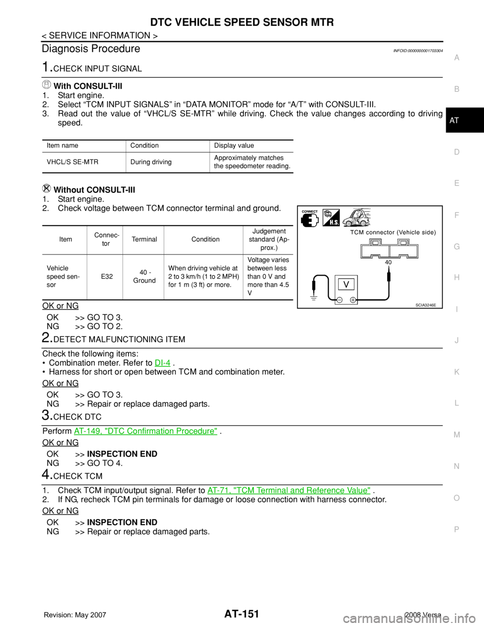
2. Check voltage between TCM connector terminal and ground.
OK or NG
OK >> GO TO 3.
NG >> GO TO 2.
2.DETECT MALFUNCTIONING ITEM
Check the following items:
• Combination meter. Refer to DI-4
.
• Harness for short or open between TCM and combination meter.
OK or NG
OK >> GO TO 3.
NG >> Repair or replace damaged parts.
3.CHECK DTC
Perform AT-149, "
DTC Confirmation Procedure" .
OK or NG
OK >>INSPECTION END
NG >> GO TO 4.
4.CHECK TCM
1. Check TCM input/output signal. Refer to AT-71, "
TCM Terminal and Reference Value" .
2. If NG, recheck TCM pin terminals for damage or loose connection with harness connector.
OK or NG
OK >>INSPECTION END
NG >> Repair or replace damaged parts.
Item name Condition Display value
VHCL/S SE-MTR During drivingApproximately matches
the speedometer reading.
Item Connec-
torTerminal ConditionJudgement
standard (Ap-
prox.)
Vehicle
speed sen-
sor E32 40 -
GroundWhen driving vehicle at
2 to 3 km/h (1 to 2 MPH)
for 1 m (3 ft) or more.Voltage varies
between less
than 0 V and
more than 4.5
V
SCIA3246E
Page 170 of 2771

AT-158
< SERVICE INFORMATION >
DTC TURBINE REVOLUTION SENSOR
DTC TURBINE REVOLUTION SENSOR
DescriptionINFOID:0000000001703313
The turbine revolution sensor (power train revolution sensor) detects forward clutch drum rpm (revolutions per
minute). It is located on the input side of the automatic transaxle. The vehicle speed sensor A/T (Revolution
sensor) is located on the output side of the automatic transaxle. With the two sensors, input and output rpms
are accurately detected. As a result, optimal shift timing during deceleration and shift quality can be improved.
CONSULT-III Reference Value in Data Monitor ModeINFOID:0000000001703314
Remarks: Specification data are reference values.
On Board Diagnosis LogicINFOID:0000000001703315
• This is not an OBD-II self-diagnostic item.
• Diagnostic trouble code “TURBINE SENSOR” with CONSULT-III or 10th judgement flicker without CON-
SULT-III is detected when TCM does not receive the proper voltage signal from the sensor.
Possible CauseINFOID:0000000001703316
• Harness or connector
(The sensor circuit is open or shorted.)
• Turbine revolution sensor (power train revolution sensor)
DTC Confirmation ProcedureINFOID:0000000001703317
CAUTION:
• Always drive vehicle at a safe speed.
• Be careful not to rev engine into the red zone on the tachometer.
• If performing this “DTC Confirmation Procedure” again, always turn ignition switch OFF and wait at
least 10 seconds before continuing.
After the repair, perform the following procedure to confirm the malfunction is eliminated.
WITH CONSULT-III
1. Start engine.
2. Select “DATA MONITOR” mode for “A/T” with CONSULT-III.
3. Touch “START”.
4. Drive vehicle under the following conditions for more than 5 seconds.
SLCT LVR POSI: “D” position
VEHICLE SPEED: Higher than 40 km/h (25 MPH)
ENGINE SPEED: Higher than 1,500 rpm
THROTTLE POSI: Greater than 1.0/8 of the full throttle position
5. If the check result is NG, go to AT-160, "
Diagnosis Procedure" .
WITHOUT CONSULT-III
1. Start engine.
2. Drive vehicle under the following conditions for more than 5 seconds.
Selector lever position: “D” position
Vehicle speed: Higher than 40 km/h (25 MPH)
Engine speed: Higher than 1,500 rpm
Throttle position: 1.0/8 of the full throttle position
3. Perform self-diagnosis. Refer to AT-78, "
Diagnosis Procedure without CONSULT-III" .
4. If the check result is NG, go to AT-160, "
Diagnosis Procedure" .
Item name Condition Display value
TURBINE REV During driving (lock-up ON) Approximately matches the engine speed.
Page 181 of 2771
PNP, OD SWITCH AND CLOSED THROTTLE, WIDE OPEN THROTTLE POSI-
TION SIGNAL CIRCUIT
AT-169
< SERVICE INFORMATION >
D
E
F
G
H
I
J
K
L
MA
B
AT
N
O
P
4.CHECK PNP SWITCH
1. Turn ignition switch OFF.
2. Disconnect PNP switch harness connector.
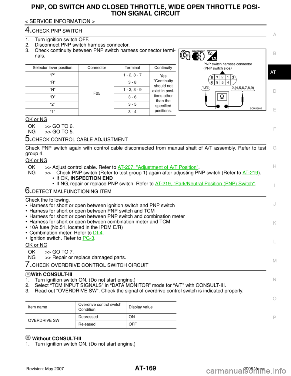
3. Check continuity between PNP switch harness connector termi-
nals.
OK or NG
OK >> GO TO 6.
NG >> GO TO 5.
5.CHECK CONTROL CABLE ADJUSTMENT
Check PNP switch again with control cable disconnected from manual shaft of A/T assembly. Refer to test
group 4.
OK or NG
OK >> Adjust control cable. Refer to AT-207, "Adjustment of A/T Position".
NG >> Check PNP switch (Refer to test group 1) again after adjusting PNP switch (Refer to AT-219
).
• If OK, INSPECTION END
• If NG, repair or replace PNP switch. Refer to AT-219, "
Park/Neutral Position (PNP) Switch".
6.DETECT MALFUNCTIONING ITEM
Check the following.
• Harness for short or open between ignition switch and PNP switch
• Harness for short or open between PNP switch and TCM
• Harness for short or open between PNP switch and combination meter
• Harness for short or open between combination meter and TCM
• 10A fuse (No.51, located in the IPDM E/R)
• Combination meter. Refer to DI-4
.
• Ignition switch. Refer to PG-3
.
OK or NG
OK >> GO TO 7.
NG >> Repair or replace damaged parts.
7.CHECK OVERDRIVE CONTROL SWITCH CIRCUIT
With CONSULT-III
1. Turn ignition switch ON. (Do not start engine.)
2. Select “TCM INPUT SIGNALS” in “DATA MONITOR” mode for “A/T” with CONSULT-III.
3. Read out “OVERDRIVE SW”. Check the signal of overdrive control switch is indicated properly.
Without CONSULT-III
1. Turn ignition switch ON. (Do not start engine.)
Selector lever position Connector Terminal Continuity
“P”
F251 - 2, 3 - 7
Ye s
*Continuity
should not
exist in posi-
tions other
than the
specified
positions. “R” 3 - 8
“N” 1 - 2, 3 - 9
“D” 3 - 6
“2” 3 - 5
“1” 3 - 4
SCIA5588E
Item nameOverdrive control switch
ConditionDisplay value
OVERDRIVE SWDepressed ON
Released OFF
Page 182 of 2771
AT-170
< SERVICE INFORMATION >
PNP, OD SWITCH AND CLOSED THROTTLE, WIDE OPEN THROTTLE POSI-
TION SIGNAL CIRCUIT
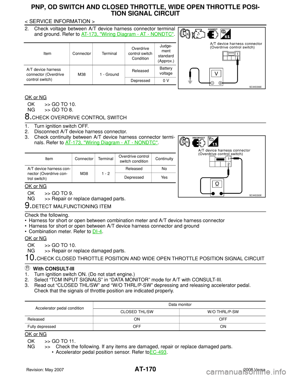
2. Check voltage between A/T device harness connector terminal
and ground. Refer to AT-173, "
Wiring Diagram - AT - NONDTC".
OK or NG
OK >> GO TO 10.
NG >> GO TO 8.
8.CHECK OVERDRIVE CONTROL SWITCH
1. Turn ignition switch OFF.
2. Disconnect A/T device harness connector.
3. Check continuity between A/T device harness connector termi-
nals. Refer to AT-173, "
Wiring Diagram - AT - NONDTC".
OK or NG
OK >> GO TO 9.
NG >> Repair or replace damaged parts.
9.DETECT MALFUNCTIONING ITEM
Check the following.
• Harness for short or open between combination meter and A/T device harness connector
• Harness for short or open between A/T device harness connector and ground
• Combination meter. Refer to DI-4
.
OK or NG
OK >> GO TO 10.
NG >> Repair or replace damaged parts.
10.CHECK CLOSED THROTTLE POSITION AND WIDE OPEN THROTTLE POSITION SIGNAL CIRCUIT
With CONSULT-III
1. Turn ignition switch ON. (Do not start engine.)
2. Select “TCM INPUT SIGNALS” in “DATA MONITOR” mode for A/T with CONSULT-III.
3. Read out “CLOSED THL/SW” and “W/O THRL/P-SW” depressing and releasing accelerator pedal.
Check that the signals of throttle position are indicated properly.
OK or NG
OK >> GO TO 11.
NG >> Check the following. If any items are damaged, repair or replace damaged parts.
• Accelerator pedal position sensor. Refer toEC-493
.
Item Connector TerminalOverdrive
control switch
ConditionJudge-
ment
standard
(Approx.)
A/T device harness
connector (Overdrive
control switch)M38 1 - GroundReleasedBattery
voltage
Depressed 0 V
SCIA5336E
Item Connector TerminalOverdrive control
switch conditionContinuity
A/T device harness con-
nector (Overdrive con-
trol switch)M38 1 - 2Released No
Depressed Yes
SCIA5330E
Accelerator pedal conditionData monitor
CLOSED THL/SW W/O THRL/P-SW
Released ON OFF
Fully depressed OFF ON
Page 184 of 2771
AT-172
< SERVICE INFORMATION >
SHIFT POSITION INDICATOR CIRCUIT
SHIFT POSITION INDICATOR CIRCUIT
DescriptionINFOID:0000000001703331
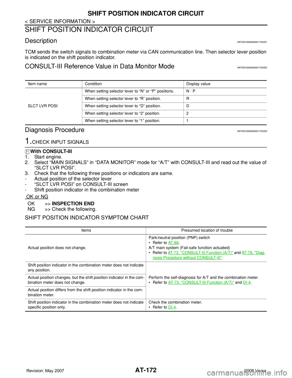
TCM sends the switch signals to combination meter via CAN communication line. Then selector lever position
is indicated on the shift position indicator.
CONSULT-III Reference Value in Data Monitor ModeINFOID:0000000001703332
Diagnosis ProcedureINFOID:0000000001703333
1.CHECK INPUT SIGNALS
With CONSULT-III
1. Start engine.
2. Select “MAIN SIGNALS” in “DATA MONITOR” mode for “A/T” with CONSULT-III and read out the value of
“SLCT LVR POSI”.
3. Check that the following three positions or indicators are same.
- Actual position of the selector lever
- “SLCT LVR POSI” on CONSULT-III screen
- Shift position indicator in the combination meter
OK or NG
OK >>INSPECTION END
NG >> Check the following.
SHIFT POSITION INDICATOR SYMPTOM CHART
Item name Condition Display value
SLCT LVR POSIWhen setting selector lever to “N” or “P” positions. N · P
When setting selector lever to “R” position. R
When setting selector lever to “D” position. D
When setting selector lever to “2” position. 2
When setting selector lever to “1” position. 1
Items Presumed location of trouble
Actual position does not change.Park/neutral position (PNP) switch
• Refer to AT- 8 6
.
A/T main system (Fail-safe function actuated)
•Refer to AT- 7 3 , "
CONSULT-III Function (A/T)" and AT- 7 8 , "Diag-
nosis Procedure without CONSULT-III".
Shift position indicator in the combination meter does not indicate
any position.
Perform the self-diagnosis for A/T and the combination meter.
• Refer to AT- 7 3 , "
CONSULT-III Function (A/T)" and DI-4. Actual position changes, but the shift position indicator in the com-
bination meter does not change.
Actual position differs from the shift position indicator in the com-
bination meter.
Shift position indicator in the combination meter does not indicate
specific position only.Check the combination meter.
• Refer to DI-4
.
Page 190 of 2771
AT-178
< SERVICE INFORMATION >
TROUBLE DIAGNOSIS FOR SYMPTOMS
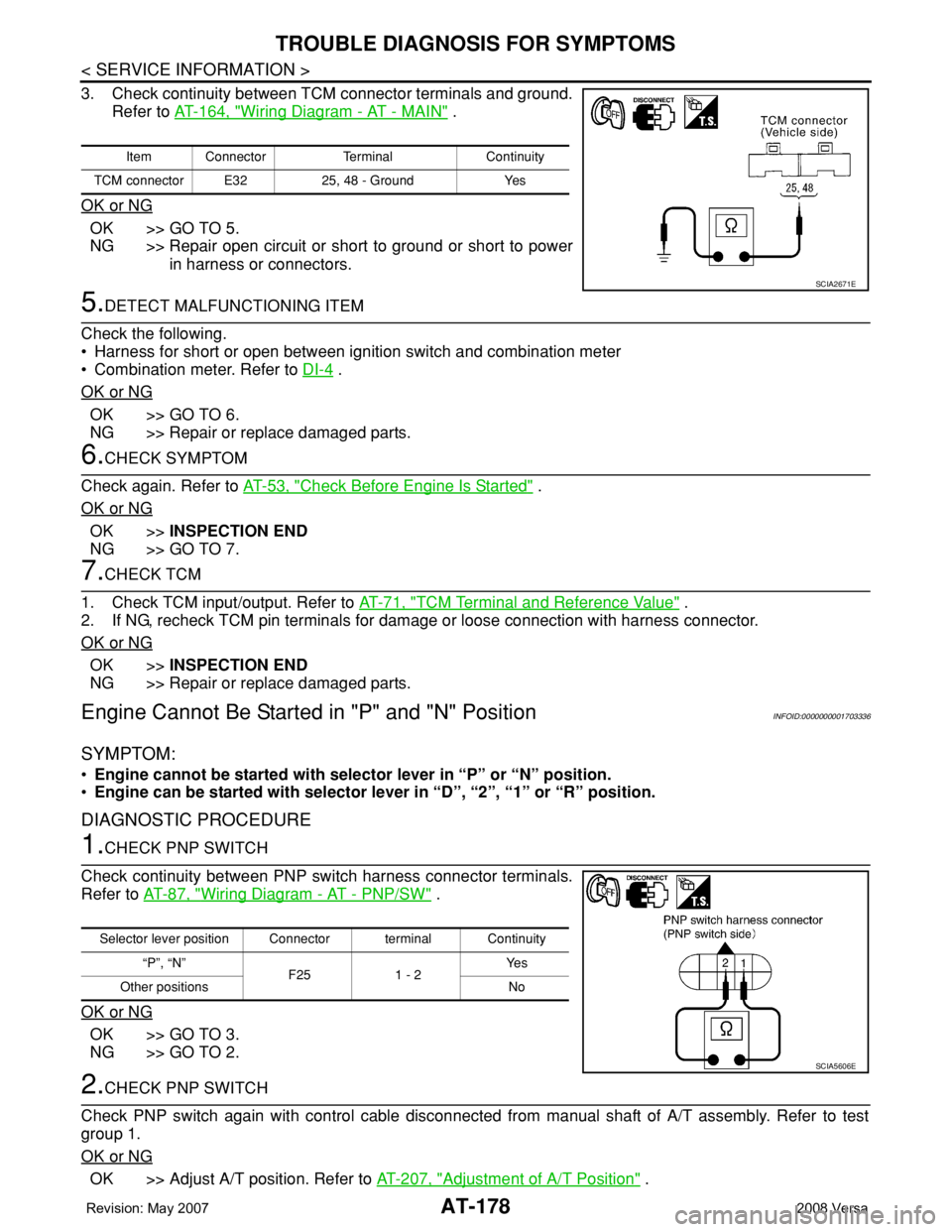
3. Check continuity between TCM connector terminals and ground.
Refer to AT-164, "
Wiring Diagram - AT - MAIN" .
OK or NG
OK >> GO TO 5.
NG >> Repair open circuit or short to ground or short to power
in harness or connectors.
5.DETECT MALFUNCTIONING ITEM
Check the following.
• Harness for short or open between ignition switch and combination meter
• Combination meter. Refer to DI-4
.
OK or NG
OK >> GO TO 6.
NG >> Repair or replace damaged parts.
6.CHECK SYMPTOM
Check again. Refer to AT-53, "
Check Before Engine Is Started" .
OK or NG
OK >>INSPECTION END
NG >> GO TO 7.
7.CHECK TCM
1. Check TCM input/output. Refer to AT-71, "
TCM Terminal and Reference Value" .
2. If NG, recheck TCM pin terminals for damage or loose connection with harness connector.
OK or NG
OK >>INSPECTION END
NG >> Repair or replace damaged parts.
Engine Cannot Be Started in "P" and "N" PositionINFOID:0000000001703336
SYMPTOM:
•Engine cannot be started with selector lever in “P” or “N” position.
•Engine can be started with selector lever in “D”, “2”, “1” or “R” position.
DIAGNOSTIC PROCEDURE
1.CHECK PNP SWITCH
Check continuity between PNP switch harness connector terminals.
Refer to AT-87, "
Wiring Diagram - AT - PNP/SW" .
OK or NG
OK >> GO TO 3.
NG >> GO TO 2.
2.CHECK PNP SWITCH
Check PNP switch again with control cable disconnected from manual shaft of A/T assembly. Refer to test
group 1.
OK or NG
OK >> Adjust A/T position. Refer to AT-207, "Adjustment of A/T Position" .
Item Connector Terminal Continuity
TCM connector E32 25, 48 - Ground Yes
SCIA2671E
Selector lever position Connector terminal Continuity
“P”, “N”
F25 1 - 2Ye s
Other positions No
SCIA5606E