2008 NISSAN TIIDA Window regulator
[x] Cancel search: Window regulatorPage 1902 of 2771
GW-1
BODY
C
D
E
F
G
H
J
K
L
M
SECTION GW
A
B
GW
N
O
P
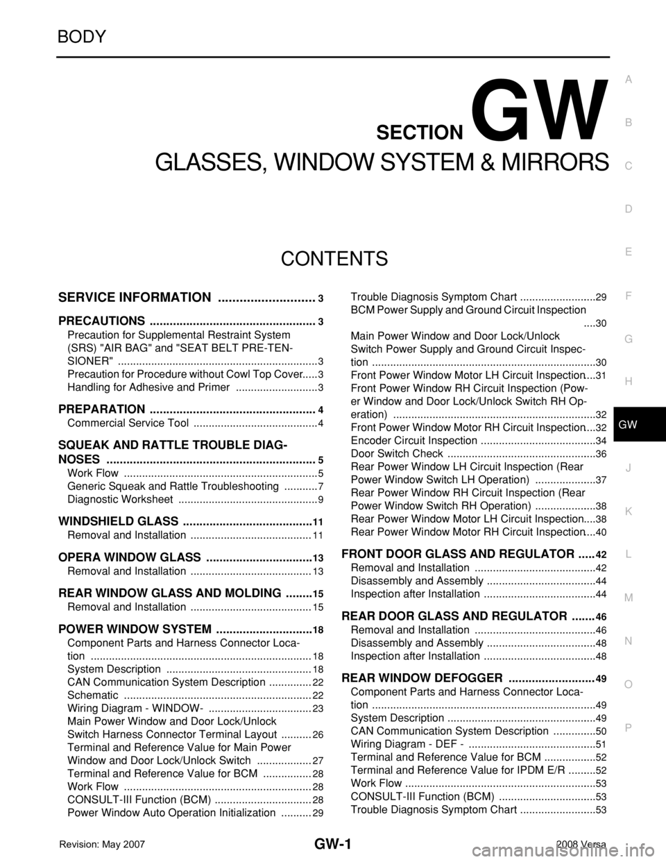
CONTENTS
GLASSES, WINDOW SYSTEM & MIRRORS
SERVICE INFORMATION ............................3
PRECAUTIONS ...................................................3
Precaution for Supplemental Restraint System
(SRS) "AIR BAG" and "SEAT BELT PRE-TEN-
SIONER" ...................................................................
3
Precaution for Procedure without Cowl Top Cover ......3
Handling for Adhesive and Primer ............................3
PREPARATION ...................................................4
Commercial Service Tool ..........................................4
SQUEAK AND RATTLE TROUBLE DIAG-
NOSES ................................................................
5
Work Flow .................................................................5
Generic Squeak and Rattle Troubleshooting ............7
Diagnostic Worksheet ...............................................9
WINDSHIELD GLASS ........................................11
Removal and Installation .........................................11
OPERA WINDOW GLASS .................................13
Removal and Installation .........................................13
REAR WINDOW GLASS AND MOLDING .........15
Removal and Installation .........................................15
POWER WINDOW SYSTEM ..............................18
Component Parts and Harness Connector Loca-
tion ..........................................................................
18
System Description .................................................18
CAN Communication System Description ...............22
Schematic ...............................................................22
Wiring Diagram - WINDOW- ...................................23
Main Power Window and Door Lock/Unlock
Switch Harness Connector Terminal Layout ...........
26
Terminal and Reference Value for Main Power
Window and Door Lock/Unlock Switch ...................
27
Terminal and Reference Value for BCM .................28
Work Flow ...............................................................28
CONSULT-III Function (BCM) .................................28
Power Window Auto Operation Initialization ...........29
Trouble Diagnosis Symptom Chart ..........................29
BCM Power Supply and Ground Circuit Inspection
....
30
Main Power Window and Door Lock/Unlock
Switch Power Supply and Ground Circuit Inspec-
tion ...........................................................................
30
Front Power Window Motor LH Circuit Inspection ....31
Front Power Window RH Circuit Inspection (Pow-
er Window and Door Lock/Unlock Switch RH Op-
eration) ....................................................................
32
Front Power Window Motor RH Circuit Inspection ....32
Encoder Circuit Inspection .......................................34
Door Switch Check ..................................................36
Rear Power Window LH Circuit Inspection (Rear
Power Window Switch LH Operation) .....................
37
Rear Power Window RH Circuit Inspection (Rear
Power Window Switch RH Operation) .....................
38
Rear Power Window Motor LH Circuit Inspection ....38
Rear Power Window Motor RH Circuit Inspection ....40
FRONT DOOR GLASS AND REGULATOR .....42
Removal and Installation .........................................42
Disassembly and Assembly .....................................44
Inspection after Installation ......................................44
REAR DOOR GLASS AND REGULATOR .......46
Removal and Installation .........................................46
Disassembly and Assembly .....................................48
Inspection after Installation ......................................48
REAR WINDOW DEFOGGER ..........................49
Component Parts and Harness Connector Loca-
tion ...........................................................................
49
System Description ..................................................49
CAN Communication System Description ...............50
Wiring Diagram - DEF - ...........................................51
Terminal and Reference Value for BCM ..................52
Terminal and Reference Value for IPDM E/R ..........52
Work Flow ................................................................53
CONSULT-III Function (BCM) .................................53
Trouble Diagnosis Symptom Chart ..........................53
Page 1930 of 2771
POWER WINDOW SYSTEM
GW-29
< SERVICE INFORMATION >
C
D
E
F
G
H
J
K
L
MA
B
GW
N
O
P
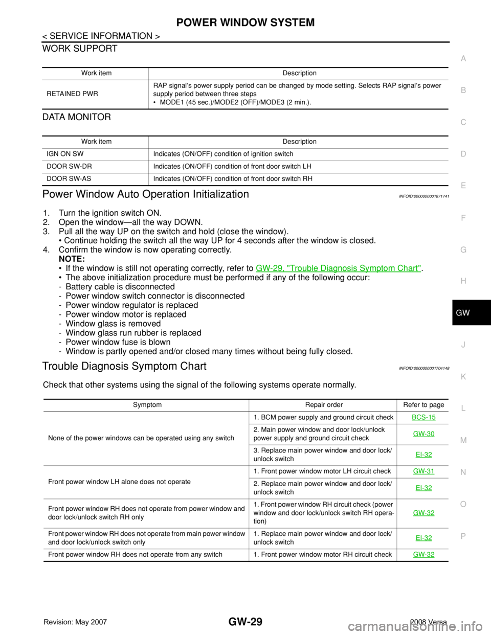
WORK SUPPORT
DATA MONITOR
Power Window Auto Operation InitializationINFOID:0000000001871741
1. Turn the ignition switch ON.
2. Open the window—all the way DOWN.
3. Pull all the way UP on the switch and hold (close the window).
• Continue holding the switch all the way UP for 4 seconds after the window is closed.
4. Confirm the window is now operating correctly.
NOTE:
• If the window is still not operating correctly, refer to GW-29, "
Trouble Diagnosis Symptom Chart".
• The above initialization procedure must be performed if any of the following occur:
- Battery cable is disconnected
- Power window switch connector is disconnected
- Power window regulator is replaced
- Power window motor is replaced
- Window glass is removed
- Window glass run rubber is replaced
- Power window fuse is blown
- Window is partly opened and/or closed many times without being fully closed.
Trouble Diagnosis Symptom ChartINFOID:0000000001704148
Check that other systems using the signal of the following systems operate normally.
Work item Description
RETAINED PWRRAP signal’s power supply period can be changed by mode setting. Selects RAP signal’s power
supply period between three steps
• MODE1 (45 sec.)/MODE2 (OFF)/MODE3 (2 min.).
Work item Description
IGN ON SW Indicates (ON/OFF) condition of ignition switch
DOOR SW-DR Indicates (ON/OFF) condition of front door switch LH
DOOR SW-AS Indicates (ON/OFF) condition of front door switch RH
Symptom Repair order Refer to page
None of the power windows can be operated using any switch1. BCM power supply and ground circuit checkBCS-15
2. Main power window and door lock/unlock
power supply and ground circuit checkGW-30
3. Replace main power window and door lock/
unlock switchEI-32
Front power window LH alone does not operate1. Front power window motor LH circuit checkGW-312. Replace main power window and door lock/
unlock switchEI-32
Front power window RH does not operate from power window and
door lock/unlock switch RH only1. Front power window RH circuit check (power
window and door lock/unlock switch RH opera-
tion)GW-32
Front power window RH does not operate from main power window
and door lock/unlock switch only1. Replace main power window and door lock/
unlock switchEI-32
Front power window RH does not operate from any switch 1. Front power window motor RH circuit checkGW-32
Page 1943 of 2771
GW-42
< SERVICE INFORMATION >
FRONT DOOR GLASS AND REGULATOR
FRONT DOOR GLASS AND REGULATOR
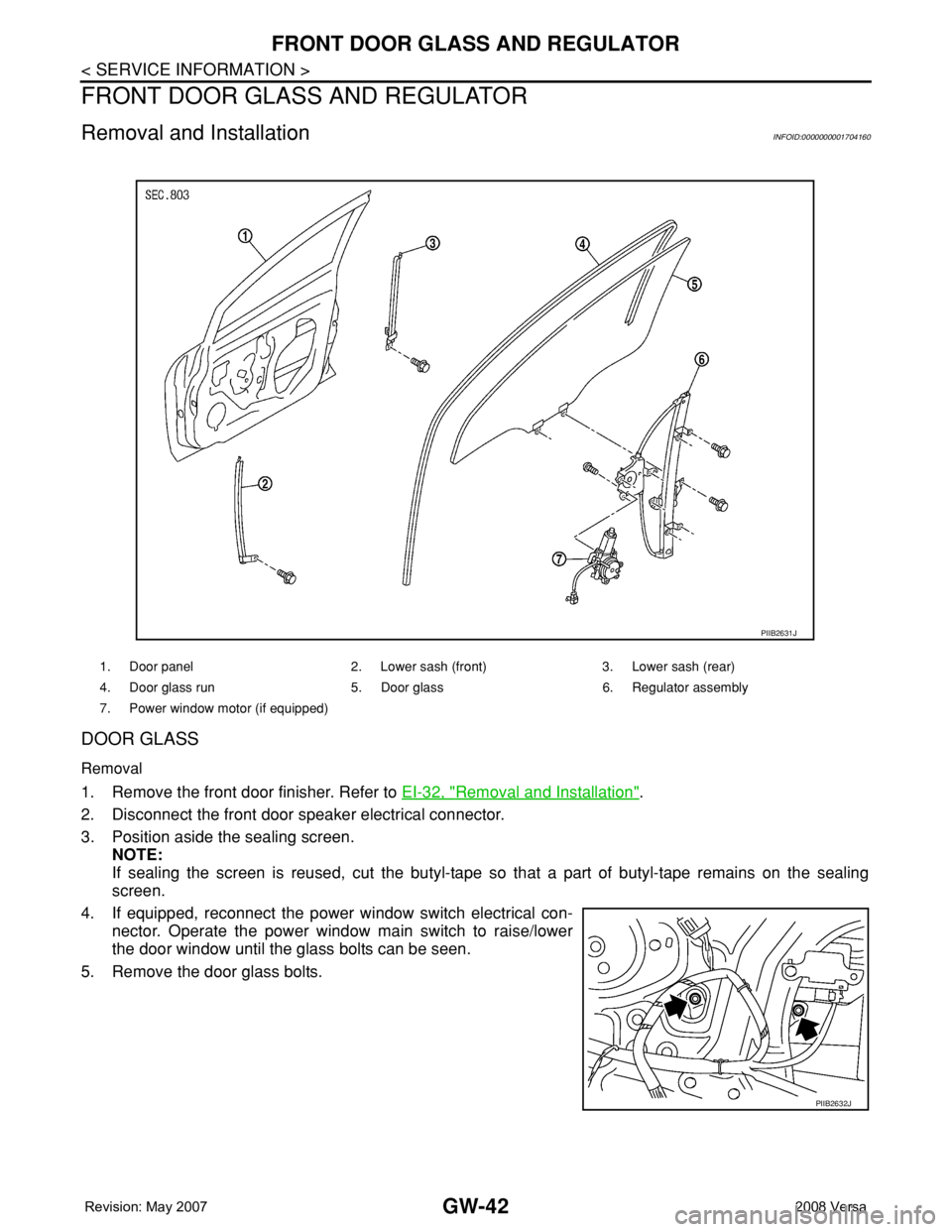
Removal and InstallationINFOID:0000000001704160
DOOR GLASS
Removal
1. Remove the front door finisher. Refer to EI-32, "Removal and Installation".
2. Disconnect the front door speaker electrical connector.
3. Position aside the sealing screen.
NOTE:
If sealing the screen is reused, cut the butyl-tape so that a part of butyl-tape remains on the sealing
screen.
4. If equipped, reconnect the power window switch electrical con-
nector. Operate the power window main switch to raise/lower
the door window until the glass bolts can be seen.
5. Remove the door glass bolts.
1. Door panel 2. Lower sash (front) 3. Lower sash (rear)
4. Door glass run 5. Door glass 6. Regulator assembly
7. Power window motor (if equipped)
PIIB2631J
PIIB2632J
Page 1944 of 2771
FRONT DOOR GLASS AND REGULATOR
GW-43
< SERVICE INFORMATION >
C
D
E
F
G
H
J
K
L
MA
B
GW
N
O
P
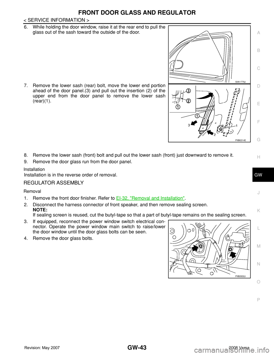
6. While holding the door window, raise it at the rear end to pull the
glass out of the sash toward the outside of the door.
7. Remove the lower sash (rear) bolt, move the lower end portion
ahead of the door panel.(3) and pull out the insertion (2) of the
upper end from the door panel to remove the lower sash
(rear)(1).
8. Remove the lower sash (front) bolt and pull out the lower sash (front) just downward to remove it.
9. Remove the door glass run from the door panel.
Installation
Installation is in the reverse order of removal.
REGULATOR ASSEMBLY
Removal
1. Remove the front door finisher. Refer to EI-32, "Removal and Installation".
2. Disconnect the harness connector of front speaker, and then remove sealing screen.
NOTE:
If sealing screen is reused, cut the butyl-tape so that a part of butyl-tape remains on the sealing screen.
3. If equipped, reconnect the power window switch electrical con-
nector. Operate the power window main switch to raise/lower
the door window until the door glass bolts can be seen.
4. Remove the door glass bolts.
SIIA1779J
PIIB6314E
PIIB2632J
Page 1945 of 2771
GW-44
< SERVICE INFORMATION >
FRONT DOOR GLASS AND REGULATOR
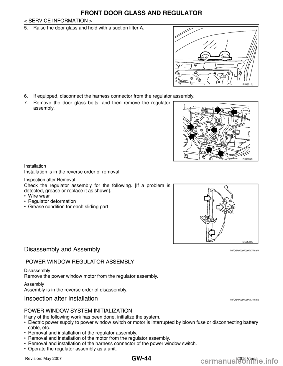
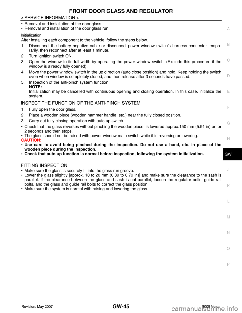
5. Raise the door glass and hold with a suction lifter A.
6. If equipped, disconnect the harness connector from the regulator assembly.
7. Remove the door glass bolts, and then remove the regulator
assembly.
Installation
Installation is in the reverse order of removal.
Inspection after Removal
Check the regulator assembly for the following. [If a problem is
detected, grease or replace it as shown].
• Wire wear
• Regulator deformation
• Grease condition for each sliding part
Disassembly and AssemblyINFOID:0000000001704161
POWER WINDOW REGULATOR ASSEMBLY
Disassembly
Remove the power window motor from the regulator assembly.
Assembly
Assembly is in the reverse order of disassembly.
Inspection after InstallationINFOID:0000000001704162
POWER WINDOW SYSTEM INITIALIZATION
If any of the following work has been done, initialize the system.
• Electric power supply to power window switch or motor is interrupted by blown fuse or disconnecting battery
cable, etc.
• Removal and installation of the regulator assembly.
• Removal and installation of the motor from the regulator assembly.
• Removal and installation of the harness connector of the power window switch.
• Operate the regulator assembly as a unit.
PIIB3510J
PIIB2633J
SIIA1781J
Page 1946 of 2771
FRONT DOOR GLASS AND REGULATOR
GW-45
< SERVICE INFORMATION >
C
D
E
F
G
H
J
K
L
MA
B
GW
N
O
P
• Removal and installation of the door glass.
• Removal and installation of the door glass run.
Initialization
After installing each component to the vehicle, follow the steps below.
1. Disconnect the battery negative cable or disconnect power window switch's harness connector tempo-
rarily, then reconnect after at least 1 minute.
2. Turn ignition switch ON.
3. Open the window to its full width by operating the power window switch. (Exclude this procedure if the
window is already fully opened).
4. Move the power window switch in the up direction (auto close position) and hold. Keep holding the switch
even when window is completely closed, and then release after 3 seconds have passed.
5. Inspection of the anti-pinch system function.
NOTE:
Initialization may be cancelled with continuous opening and closing operation. In this case, initialize the
system.
INSPECT THE FUNCTION OF THE ANTI-PINCH SYSTEM
1. Fully open the door glass.
2. Place a wooden piece (wooden hammer handle, etc.) near the fully closed position.
3. Carry out fully closing operation with auto up switch.
• Check that the glass reverses without pinching the wooden piece, is lowered approx.150 mm (5.91 in) or for
2 seconds and then stops.
• The glass should not be raised with power window main switch while it is reversing or lowering.
CAUTION:
• Use care to avoid being pinched during the inspection. Do not use a hand, etc. in place of the
wooden piece during the inspection.
• Check that auto up function is normal before inspection, following the system initialization.
FITTING INSPECTION
• Make sure the glass is securely fit into the glass run groove.
• Lower the glass slightly [approx. 10 to 20 mm (0.39 to 0.79 in)] and make sure the clearance to the sash is
parallel. If the clearance between the glass and sash is not parallel, loosen the regulator bolts, guide rail
bolts, and the glass and guide rail bolts to correct the glass position.
• Make sure the system is normal with raising and lowering the glass.
Page 1947 of 2771
GW-46
< SERVICE INFORMATION >
REAR DOOR GLASS AND REGULATOR
REAR DOOR GLASS AND REGULATOR
Removal and InstallationINFOID:0000000001704163
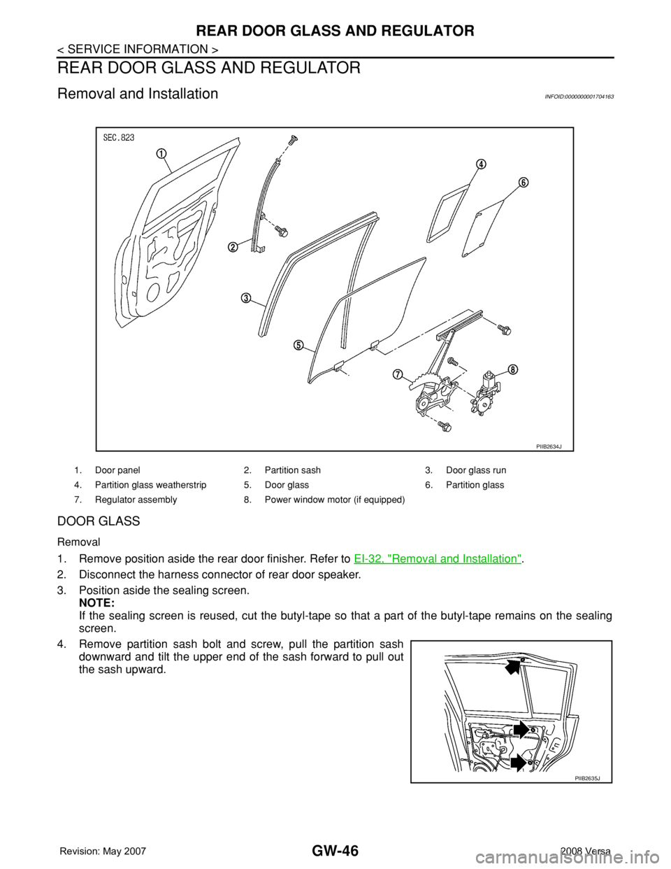
DOOR GLASS
Removal
1. Remove position aside the rear door finisher. Refer to EI-32, "Removal and Installation".
2. Disconnect the harness connector of rear door speaker.
3. Position aside the sealing screen.
NOTE:
If the sealing screen is reused, cut the butyl-tape so that a part of the butyl-tape remains on the sealing
screen.
4. Remove partition sash bolt and screw, pull the partition sash
downward and tilt the upper end of the sash forward to pull out
the sash upward.
1. Door panel 2. Partition sash 3. Door glass run
4. Partition glass weatherstrip 5. Door glass 6. Partition glass
7. Regulator assembly 8. Power window motor (if equipped)
PIIB2634J
PIIB2635J
Page 1948 of 2771
REAR DOOR GLASS AND REGULATOR
GW-47
< SERVICE INFORMATION >
C
D
E
F
G
H
J
K
L
MA
B
GW
N
O
P
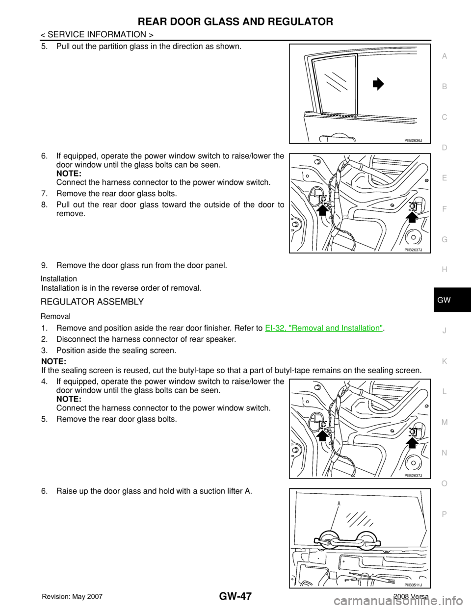
5. Pull out the partition glass in the direction as shown.
6. If equipped, operate the power window switch to raise/lower the
door window until the glass bolts can be seen.
NOTE:
Connect the harness connector to the power window switch.
7. Remove the rear door glass bolts.
8. Pull out the rear door glass toward the outside of the door to
remove.
9. Remove the door glass run from the door panel.
Installation
Installation is in the reverse order of removal.
REGULATOR ASSEMBLY
Removal
1. Remove and position aside the rear door finisher. Refer to EI-32, "Removal and Installation".
2. Disconnect the harness connector of rear speaker.
3. Position aside the sealing screen.
NOTE:
If the sealing screen is reused, cut the butyl-tape so that a part of butyl-tape remains on the sealing screen.
4. If equipped, operate the power window switch to raise/lower the
door window until the glass bolts can be seen.
NOTE:
Connect the harness connector to the power window switch.
5. Remove the rear door glass bolts.
6. Raise up the door glass and hold with a suction lifter A.
PIIB2636J
PIIB2637J
PIIB2637J
PIIB3511J