2008 NISSAN TIIDA rear suspension
[x] Cancel search: rear suspensionPage 1 of 2771

-1
QUICK REFERENCE INDEX
AGENERAL INFORMATIONGIGeneral Information
BENGINEEMEngine Mechanical
LUEngine Lubrication System
COEngine Cooling System
ECEngine Control System
FLFuel System
EXExhaust System
ACCAccelerator Control System
CTRANSMISSION/
TRANSAXLECLClutch System
MTManual Transaxle
ATAutomatic Transaxle
CVTCVT
DDRIVELINE/AXLEFAXFront Axle
RAXRear Axle
ESUSPENSIONFSUFront Suspension
RSURear Suspension
WTRoad Wheels & Tires
FBRAKESBRBrake System
PBParking Brake System
BRCBrake Control System
GSTEERINGPSPower Steering System
STCSteering Control System
HRESTRAINTSSBSeat Belts
SRSSupplemental Restraint System (SRS)
IBODYBLBody, Lock & Security System
GWGlasses, Window System & Mirrors
RFRoof
EIExterior & Interior
IPInstrument Panel
SESeat
JAIR CONDITIONERMTCManual Air Conditioner
KELECTRICALSCStarting & Charging System
LTLighting System
DIDriver Information System
WWWiper, Washer & Horn
BCSBody Control System
LANLAN System
AVAudio Visual, Navigation & Telephone System
ACSAuto Cruise Control System
PGPower Supply, Ground & Circuit Elements
LMAINTENANCEMAMaintenance
Edition: May 2007
Revision: May 2007
Publication No. SM8E-1C11U0
B
D
© 2007 NISSAN NORTH AMERICA, INC.
All rights reserved. No part of this Service Manual may be reproduced or stored in a retrieval system, or transmitted in any
form, or by any means, electronic, mechanical, photo-copying, recording or otherwise, without the prior written permission
of Nissan North America Inc.
A
C
E
F
G
H
I
J
K
L
M
Page 662 of 2771

BL-228
< SERVICE INFORMATION >
BODY REPAIR
4. Front pillar inner reinforcement (RH&LH)
5. Lower dash reinforcement
6. 4th crossmember (RH&LH)
7. Front side member rear extension (RH&LH)
8. 3rd crossmember (RH&LH)
9. Front seat outer rear bracket (RH&LH)
10. Front seat inner rear bracket (RH&LH)
11. 2nd crossmember (RH&LH)
12. Front seat outer front bracket (RH&LH)
13. Front seat inner front bracket (RH&LH)
14. Fender bracket (RH&LH)
15. Strut housing assembly RH
16. Cowl top side upper (RH&LH)
17. Front strut housing (RH&LH)
18. Upper torque rod reinforcement
19. Closing plate assembly RH
20. Engine mount reinforcement
21. Strut tower front reinforcement RH
22. Front hoodledge lower RH
23. Frame bracket outer (RH&LH)
24. Front bumper support bracket (RH&LH)
25. Closing plate (RH&LH)
26. Front suspension rear bracket (RH&LH)
27. Front side member outrigger (RH&LH)
28. Front side member assembly (RH&LH)
29. Front side member (RH&LH)
30. Frame bracket (RH&LH)
31. Closing plate assembly LH
32. Hoodledge connector (RH&LH)
33. Radiator core side support (RH&LH)
34. Radiator core support upper (RH&LH)
35. Hoodledge upper (RH&LH)
36. Hoodledge reinforcement assembly (RH&LH)
37. Dash side (RH&LH)
38. Dash side assembly (RH& LH)
39. Front floor reinforcement (RH&LH)
40. Front floor front (RH&LH)
41. Front floor center
42. Rear seat crossmember
43. Rear center crossmember
44. Rear seat upper crossmember
45. Rear side member (RH&LH)
46. Sill inner extension (RH&LH)
47. Rear side member extension (RH&LH)
48. Rear side member assembly (RH & LH)
49. Rear floor front
50. Rear floor front assembly
51. Rear floor side (RH&LH)
52. Rear floor rear
Page 715 of 2771
BODY REPAIR
BL-281
< SERVICE INFORMATION >
C
D
E
F
G
H
J
K
L
MA
B
BL
N
O
P
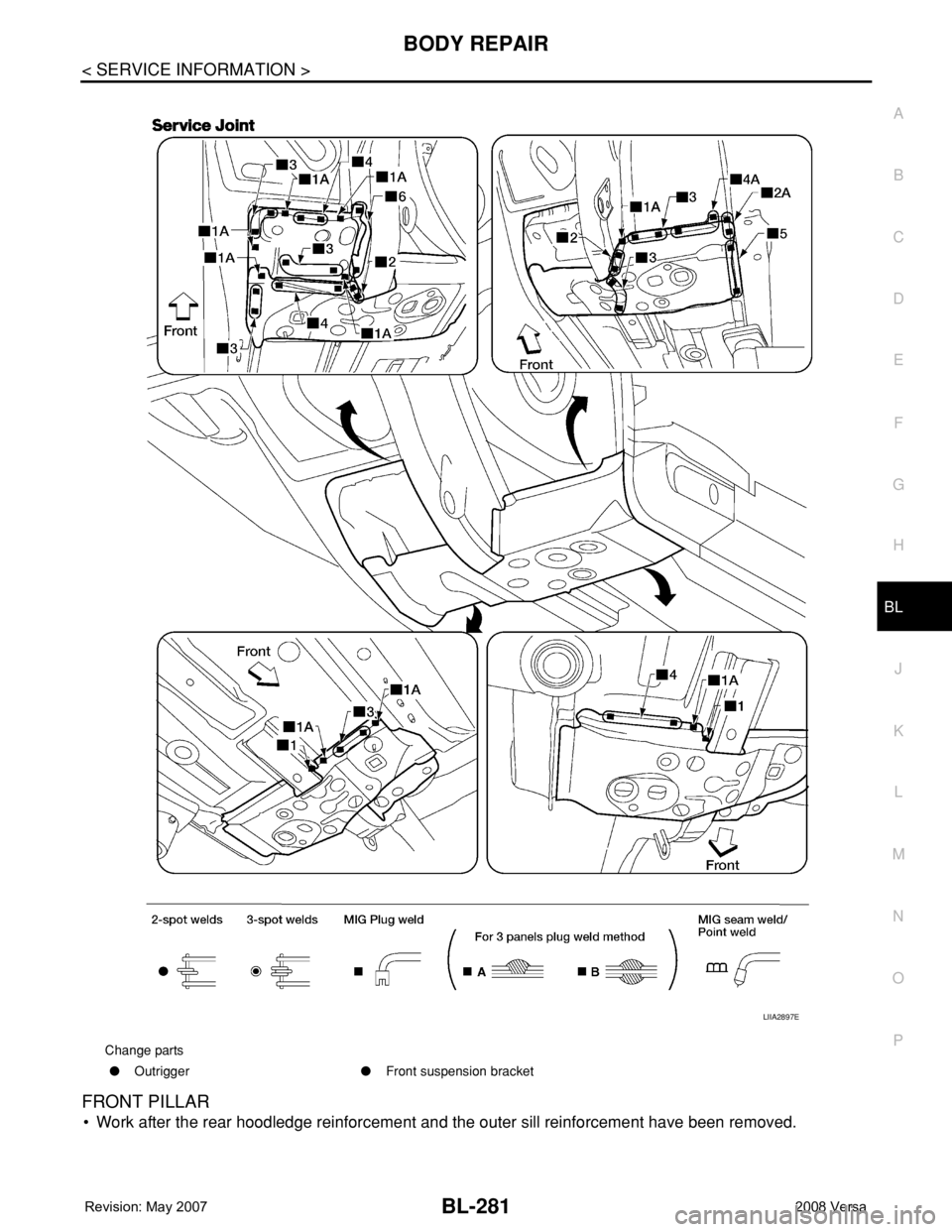
FRONT PILLAR
• Work after the rear hoodledge reinforcement and the outer sill reinforcement have been removed.
Change parts
●Outrigger●Front suspension bracket
LIIA2897E
Page 798 of 2771
![NISSAN TIIDA 2008 Service Repair Manual WHEEL SENSORS
BRC-33
< SERVICE INFORMATION >[ABS]
C
D
E
G
H
I
J
K
L
MA
B
BRC
N
O
P
• When installing rear wheel sensor, press rubber grommets of suspension arm bracket and harness of side
member all NISSAN TIIDA 2008 Service Repair Manual WHEEL SENSORS
BRC-33
< SERVICE INFORMATION >[ABS]
C
D
E
G
H
I
J
K
L
MA
B
BRC
N
O
P
• When installing rear wheel sensor, press rubber grommets of suspension arm bracket and harness of side
member all](/manual-img/5/57399/w960_57399-797.png)
WHEEL SENSORS
BRC-33
< SERVICE INFORMATION >[ABS]
C
D
E
G
H
I
J
K
L
MA
B
BRC
N
O
P
• When installing rear wheel sensor, press rubber grommets of suspension arm bracket and harness of side
member all the way in until they get locked, and be careful not to apply a twist to harness. Harness should
not be twisted after installation. (Aim the paint mark upward of vehicle.)
Page 1831 of 2771
FUEL TANK
FL-11
< SERVICE INFORMATION >
C
D
E
F
G
H
I
J
K
L
MA
FL
N
P O
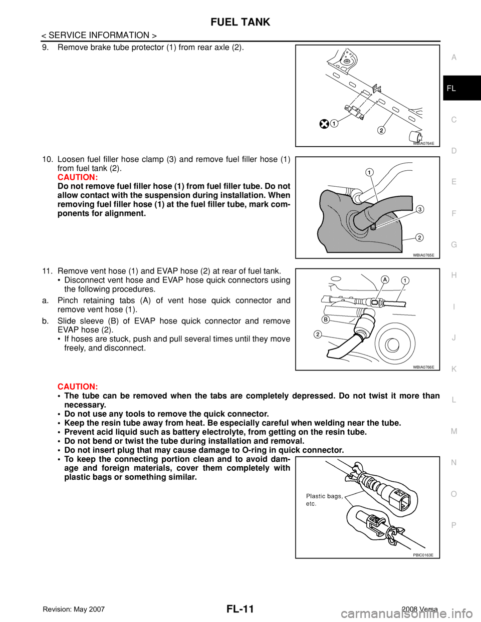
9. Remove brake tube protector (1) from rear axle (2).
10. Loosen fuel filler hose clamp (3) and remove fuel filler hose (1)
from fuel tank (2).
CAUTION:
Do not remove fuel filler hose (1) from fuel filler tube. Do not
allow contact with the suspension during installation. When
removing fuel filler hose (1) at the fuel filler tube, mark com-
ponents for alignment.
11. Remove vent hose (1) and EVAP hose (2) at rear of fuel tank.
• Disconnect vent hose and EVAP hose quick connectors using
the following procedures.
a. Pinch retaining tabs (A) of vent hose quick connector and
remove vent hose (1).
b. Slide sleeve (B) of EVAP hose quick connector and remove
EVAP hose (2).
• If hoses are stuck, push and pull several times until they move
freely, and disconnect.
CAUTION:
• The tube can be removed when the tabs are completely depressed. Do not twist it more than
necessary.
• Do not use any tools to remove the quick connector.
• Keep the resin tube away from heat. Be especially careful when welding near the tube.
• Prevent acid liquid such as battery electrolyte, from getting on the resin tube.
• Do not bend or twist the tube during installation and removal.
• Do not insert plug that may cause damage to O-ring in quick connector.
• To keep the connecting portion clean and to avoid dam-
age and foreign materials, cover them completely with
plastic bags or something similar.
WBIA0764E
WBIA0765E
WBIA0766E
PBIC0163E
Page 1840 of 2771
FSU-6
< SERVICE INFORMATION >
FRONT SUSPENSION ASSEMBLY
FRONT SUSPENSION ASSEMBLY
On-Vehicle Inspection and ServiceINFOID:0000000001703721
Make sure the mounting conditions (looseness, back lash) of each component and component conditions
(wear, damage) are normal.
INSPECTION OF LOWER BALL JOINT END PLAY
1. Set front wheels in a straight-ahead position. Do not depress brake pedal.
2. Place an iron bar or similar tool between transverse link and steering knuckle.
3. Measure axial end play by prying it up and down.
CAUTION:
Be careful not to damage ball joint boot. Do not damage the installation position by applying
excessive force.
STRUT INSPECTION
Check for oil leakage, damage and replace as necessary.
Wheel Alignment InspectionINFOID:0000000001703722
PRELIMINARY INSPECTION
WARNING:
Always adjust the alignment with the vehicle on a flat surface.
NOTE:
If alignment is out of specification, inspect and replace any damaged or worn rear suspension parts before
making any adjustments.
1. Check and adjust the wheel alignment with the vehicle under unladen conditions. “Unladen conditions”
means that the fuel, coolant, and lubricant are full; and that the spare tire, jack, hand tools and mats are in
their designated positions.
2. Check the tires for incorrect air pressure and excessive wear.
3. Check the wheels for run out and damage. Refer to WT-5, "
Inspection" .
4. Check the wheel bearing axial end play. Refer to FA X - 5 , "
On-Vehicle Inspection and Service" .
5. Check the shock absorbers for leaks or damage.
6. Check each mounting point of the suspension components for any excessive looseness or damage.
7. Check each link, arm, and the suspension member for any damage.
8. Check the vehicle height. Refer to FSU-17, "
Wheelarch Height (Unladen*)" .
GENERAL INFORMATION AND RECOMMENDATIONS
1. A Four-Wheel Thrust Alignment should be performed.
• This type of alignment is recommended for any NISSAN vehicle.
• The four-wheel “thrust” process helps ensure that the vehicle is properly aligned and the steering wheel
is centered.
• The alignment machine itself should be capable of accepting any NISSAN vehicle.
• The alignment machine should be checked to ensure that it is level.
2. Make sure the alignment machine is properly calibrated.
• Your alignment machine should be regularly calibrated in order to give correct information.
• Check with the manufacturer of your specific alignment machine for their recommended Service/Cali-
bration Schedule.
THE ALIGNMENT PROCESS
IMPORTANT: Use only the alignment specifications listed in this Service Manual. Refer to FSU-16, "Wheel
Alignment (Unladen*)" .
1. When displaying the alignment settings, many alignment machines use “indicators”: (Green/red, plus or
minus, Go/No Go). Do NOT use these indicators.
• The alignment specifications programmed into your alignment machine that operate these indicators
may not be correct.Axial end play : 0 mm (0 in)
Page 1841 of 2771
FRONT SUSPENSION ASSEMBLY
FSU-7
< SERVICE INFORMATION >
C
D
F
G
H
I
J
K
L
MA
B
FSU
N
O
P
• This may result in an ERROR.
2. Some newer alignment machines are equipped with an optional “Rolling Compensation” method to “com-
pensate” the sensors (alignment targets or head units). Do NOT use this “Rolling Compensation”
method.
• Use the “Jacking Compensation” method. After installing the alignment targets or head units, raise the
vehicle and rotate the wheels 1/2 turn both ways.
• See Instructions in the alignment machine you are using for more information.
CAMBER, CASTER AND KINGPIN INCLINATION ANGLES INSPECTION
• Camber, caster, kingpin inclination angles cannot be adjusted.
• Before inspection, mount front wheels onto turning radius gauge. Mount rear wheels onto a stand that has
same height so vehicle will remain horizontal.
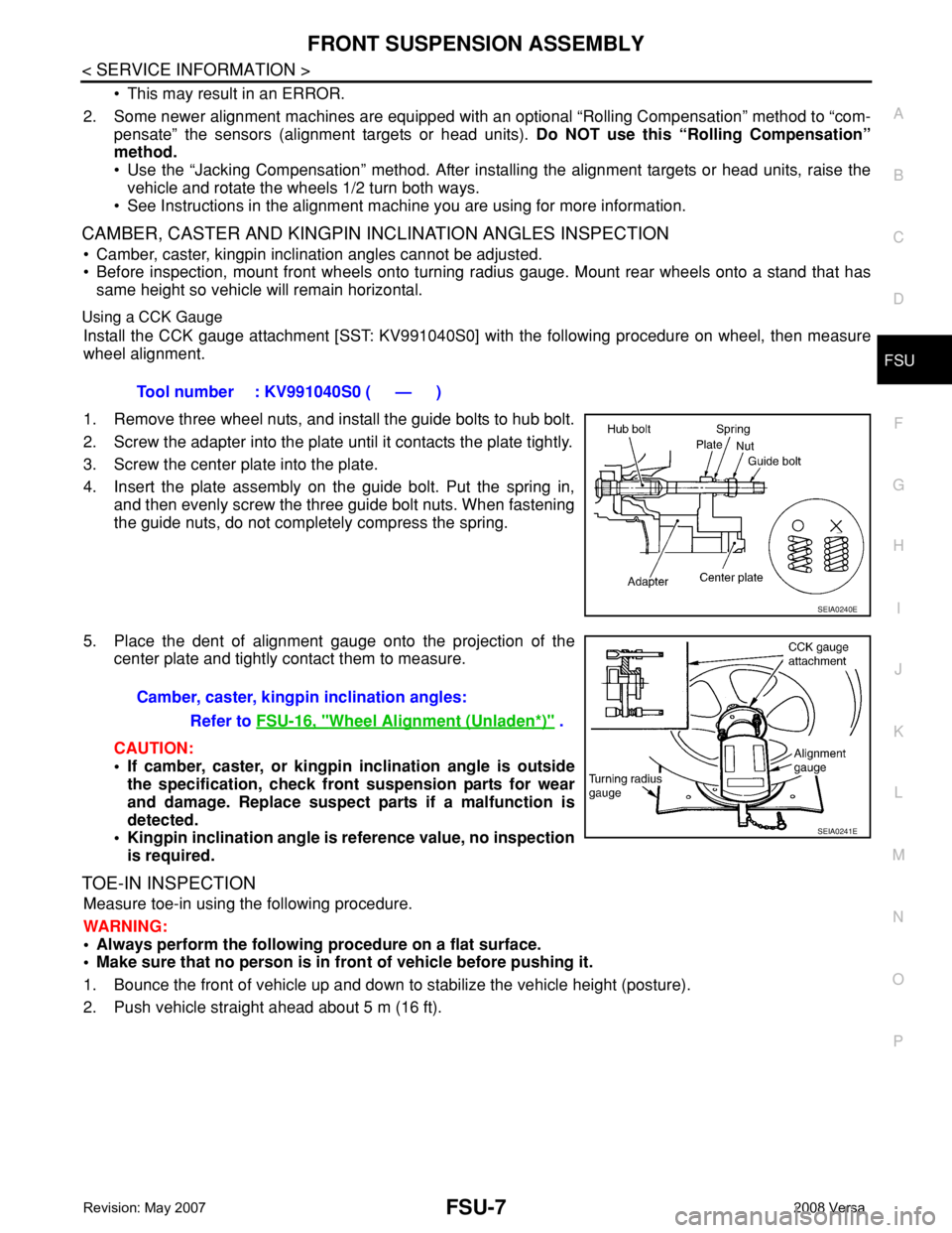
Using a CCK Gauge
Install the CCK gauge attachment [SST: KV991040S0] with the following procedure on wheel, then measure
wheel alignment.
1. Remove three wheel nuts, and install the guide bolts to hub bolt.
2. Screw the adapter into the plate until it contacts the plate tightly.
3. Screw the center plate into the plate.
4. Insert the plate assembly on the guide bolt. Put the spring in,
and then evenly screw the three guide bolt nuts. When fastening
the guide nuts, do not completely compress the spring.
5. Place the dent of alignment gauge onto the projection of the
center plate and tightly contact them to measure.
CAUTION:
• If camber, caster, or kingpin inclination angle is outside
the specification, check front suspension parts for wear
and damage. Replace suspect parts if a malfunction is
detected.
• Kingpin inclination angle is reference value, no inspection
is required.
TOE-IN INSPECTION
Measure toe-in using the following procedure.
WARNING:
• Always perform the following procedure on a flat surface.
• Make sure that no person is in front of vehicle before pushing it.
1. Bounce the front of vehicle up and down to stabilize the vehicle height (posture).
2. Push vehicle straight ahead about 5 m (16 ft).Tool number : KV991040S0 ( — )
SEIA0240E
Camber, caster, kingpin inclination angles:
Refer to FSU-16, "
Wheel Alignment (Unladen*)" .
SEIA0241E
Page 1842 of 2771
FSU-8
< SERVICE INFORMATION >
FRONT SUSPENSION ASSEMBLY
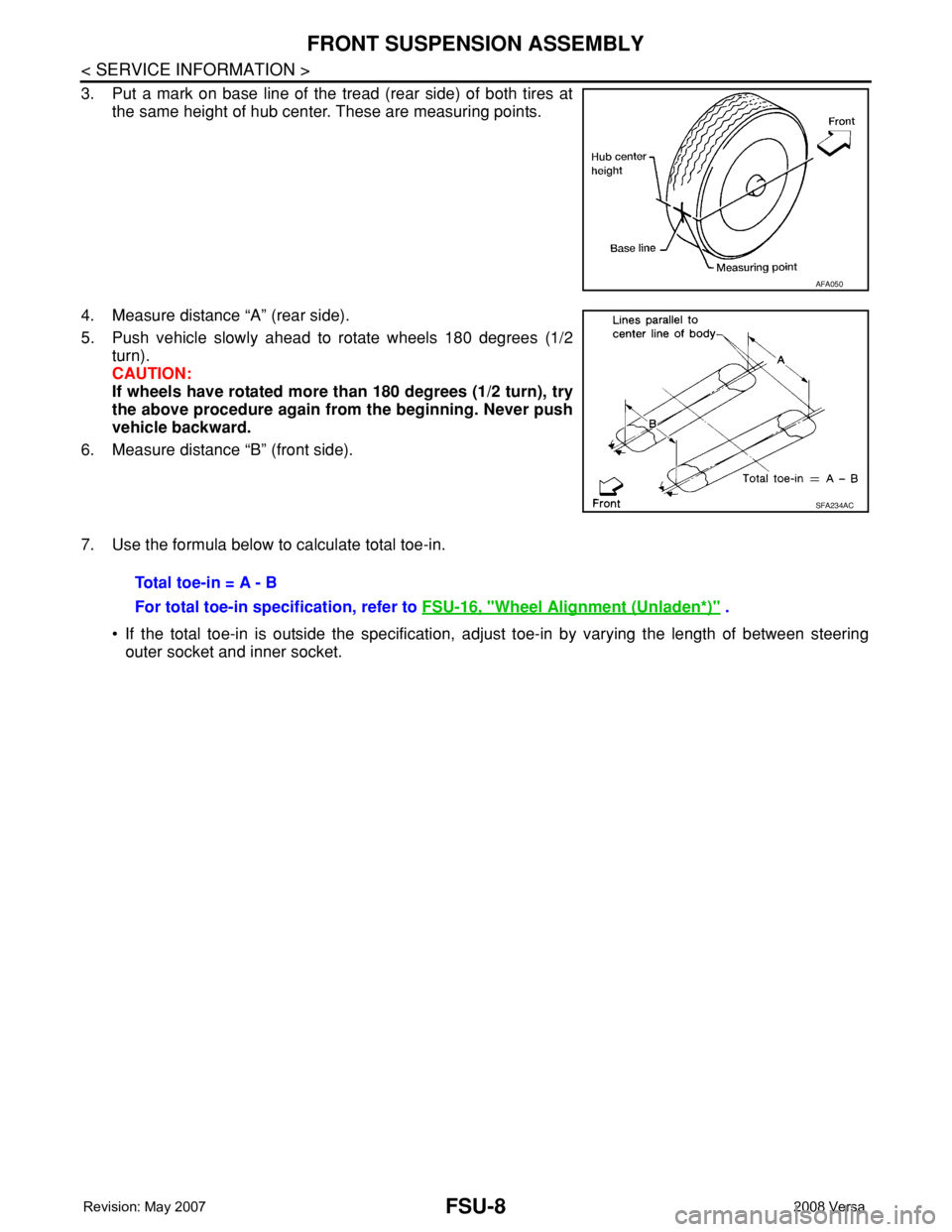
3. Put a mark on base line of the tread (rear side) of both tires at
the same height of hub center. These are measuring points.
4. Measure distance “A” (rear side).
5. Push vehicle slowly ahead to rotate wheels 180 degrees (1/2
turn).
CAUTION:
If wheels have rotated more than 180 degrees (1/2 turn), try
the above procedure again from the beginning. Never push
vehicle backward.
6. Measure distance “B” (front side).
7. Use the formula below to calculate total toe-in.
• If the total toe-in is outside the specification, adjust toe-in by varying the length of between steering
outer socket and inner socket.
AFA050
SFA234AC
Total toe-in = A - B
For total toe-in specification, refer to FSU-16, "
Wheel Alignment (Unladen*)" .