Page 268 of 2771
AT-256
< SERVICE INFORMATION >
DISASSEMBLY
48. Remove return spring (2) from parking shaft (3) using a flat-
bladed screwdriver.
(1): Parking pawl
•Inspect return spring (2), and replace if damaged or worn.
49. Draw out parking shaft (1), and then remove parking pawl (2)
from transaxle case.
•Inspect parking shaft (1) and parking pawl (2), and replace
if damaged or worn.
50. Remove parking actuator support (1) from transaxle case.
•Inspect parking actuator support (1), and replace if dam-
aged or worn.
51. Remove snap ring from transaxle case using a flat-bladed
screwdriver.
52. Remove governor cap from transaxle case.
53. Remove O-ring from governor cap.
54. Remove LH differential side oil seal from transaxle case using a
flat-bladed screwdriver.
CAUTION:
Be careful not to scratch transaxle case.
SCIA6996E
SCIA6997E
SCIA6998E
ATM0076D
Page 272 of 2771
AT-260
< SERVICE INFORMATION >
REPAIR FOR COMPONENT PARTS
9. Install detent spring on transaxle case.
10. Tighten detent spring fitting bolt to the specified torque. Refer to
"COMPONENTS".
Oil PumpINFOID:0000000001703379
COMPONENTS
DISASSEMBLY
1. Remove seal rings (1) from oil pump assembly (2).
SAT042F
1. Oil pump housing oil seal 2. Oil pump housing 3. Outer gear
4. Inner gear 5. Oil pump cover 6. Seal ring
Refer to GI section to make sure icons (symbol marks) in the figure. Refer to GI-8, "
Component".
SCIA5908J
SCIA7016E
Page 308 of 2771

AT-296
< SERVICE INFORMATION >
REPAIR FOR COMPONENT PARTS
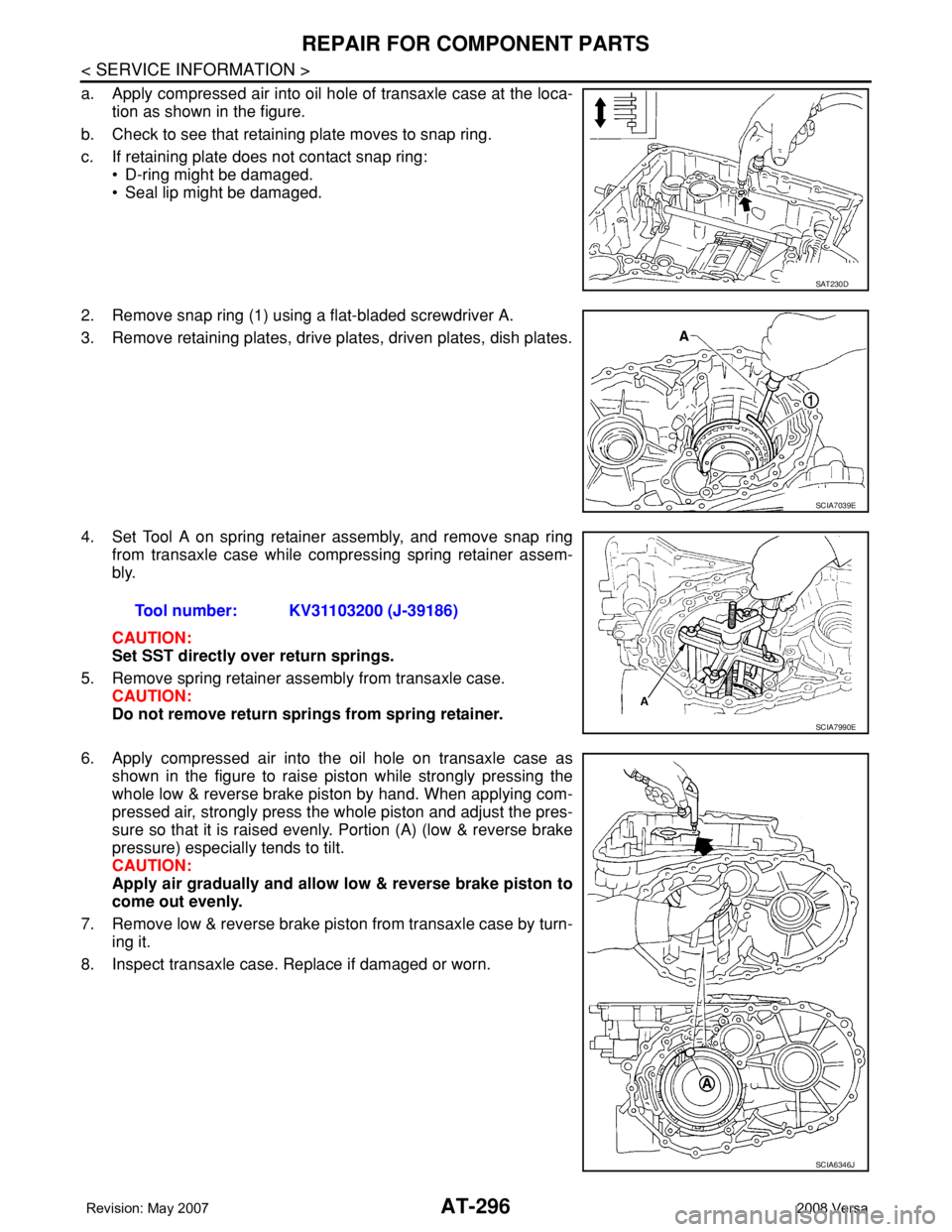
a. Apply compressed air into oil hole of transaxle case at the loca-
tion as shown in the figure.
b. Check to see that retaining plate moves to snap ring.
c. If retaining plate does not contact snap ring:
• D-ring might be damaged.
• Seal lip might be damaged.
2. Remove snap ring (1) using a flat-bladed screwdriver A.
3. Remove retaining plates, drive plates, driven plates, dish plates.
4. Set Tool A on spring retainer assembly, and remove snap ring
from transaxle case while compressing spring retainer assem-
bly.
CAUTION:
Set SST directly over return springs.
5. Remove spring retainer assembly from transaxle case.
CAUTION:
Do not remove return springs from spring retainer.
6. Apply compressed air into the oil hole on transaxle case as
shown in the figure to raise piston while strongly pressing the
whole low & reverse brake piston by hand. When applying com-
pressed air, strongly press the whole piston and adjust the pres-
sure so that it is raised evenly. Portion (A) (low & reverse brake
pressure) especially tends to tilt.
CAUTION:
Apply air gradually and allow low & reverse brake piston to
come out evenly.
7. Remove low & reverse brake piston from transaxle case by turn-
ing it.
8. Inspect transaxle case. Replace if damaged or worn.
SAT230D
SCIA7039E
Tool number: KV31103200 (J-39186)
SCIA7990E
SCIA6346J
Page 310 of 2771
AT-298
< SERVICE INFORMATION >
REPAIR FOR COMPONENT PARTS
1. Install seal lip (1) and D-ring (2) on low & reverse brake piston
(3).
2. Install low & reverse brake piston in transaxle case while turning
it.
CAUTION:
Apply ATF to inner surface of transaxle case.
3. Install spring retainer assembly (1) on low & reverse brake pis-
ton (2).
4. Set Tool A on spring retainer assembly, and install snap ring
while compressing spring retainer assembly.
CAUTION:
Set SST directly over return springs.
5. Install driven plates, dish plates, retaining plates and drive
plates.
(1): Snap ring
(2): Retaining plate
(3): Drive plate
(4): Driven plate
(5): Retaining plate
(6): Dish plate
Drive plate/Driven plate: 5/5
CAUTION:
Be careful with the order of plates
SCIA6516J
SAT239D
SCIA6020J
Tool number: KV31103200 (J-39186)
SCIA7990E
SCIA7769E
Page 317 of 2771

REPAIR FOR COMPONENT PARTS
AT-305
< SERVICE INFORMATION >
D
E
F
G
H
I
J
K
L
MA
B
AT
N
O
P
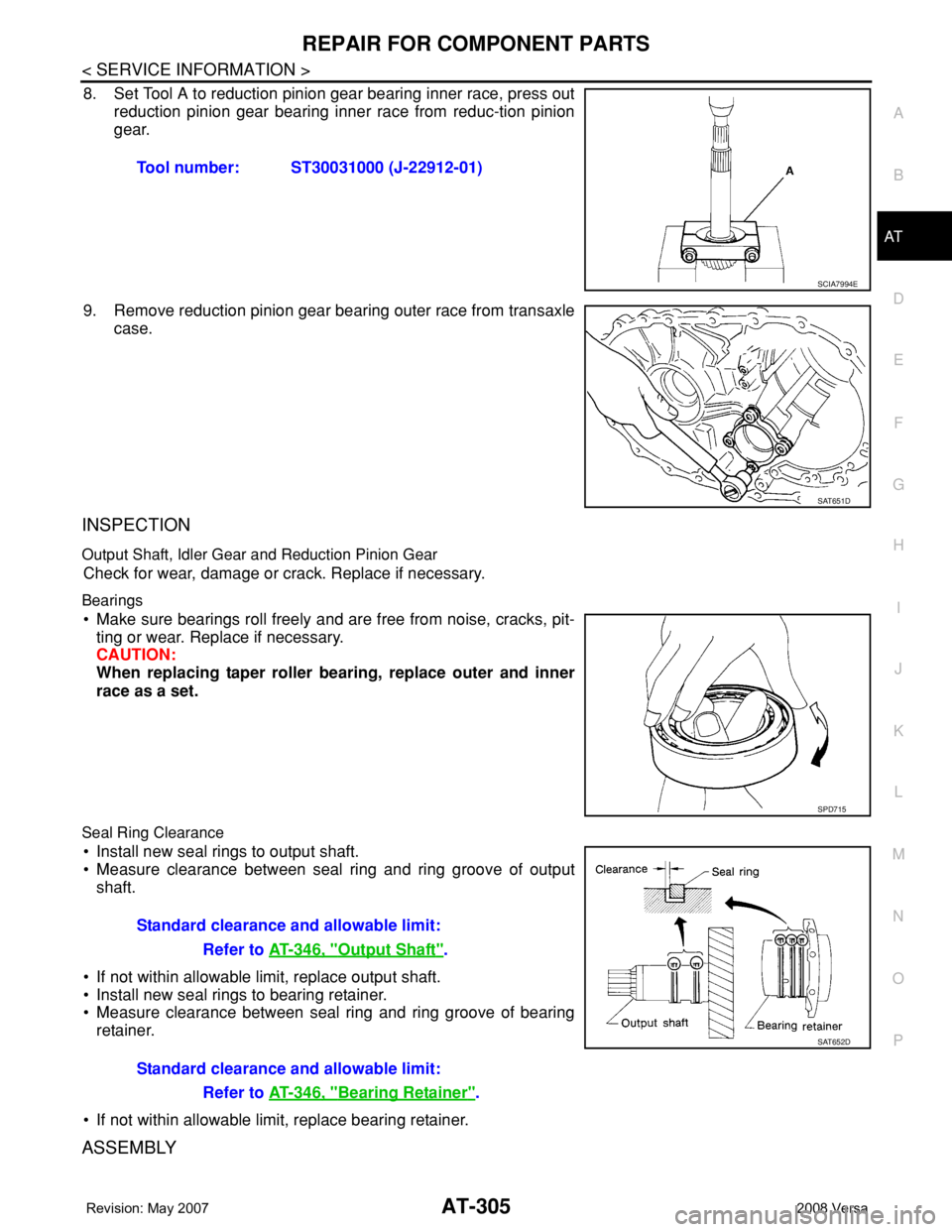
8. Set Tool A to reduction pinion gear bearing inner race, press out
reduction pinion gear bearing inner race from reduc-tion pinion
gear.
9. Remove reduction pinion gear bearing outer race from transaxle
case.
INSPECTION
Output Shaft, Idler Gear and Reduction Pinion Gear
Check for wear, damage or crack. Replace if necessary.
Bearings
• Make sure bearings roll freely and are free from noise, cracks, pit-
ting or wear. Replace if necessary.
CAUTION:
When replacing taper roller bearing, replace outer and inner
race as a set.
Seal Ring Clearance
• Install new seal rings to output shaft.
• Measure clearance between seal ring and ring groove of output
shaft.
• If not within allowable limit, replace output shaft.
• Install new seal rings to bearing retainer.
• Measure clearance between seal ring and ring groove of bearing
retainer.
• If not within allowable limit, replace bearing retainer.
ASSEMBLY
Tool number: ST30031000 (J-22912-01)
SCIA7994E
SAT651D
SPD715
Standard clearance and allowable limit:
Refer to AT-346, "
Output Shaft".
Standard clearance and allowable limit:
Refer to AT-346, "
Bearing Retainer".
SAT652D
Page 320 of 2771

AT-308
< SERVICE INFORMATION >
REPAIR FOR COMPONENT PARTS
DISASSEMBLY
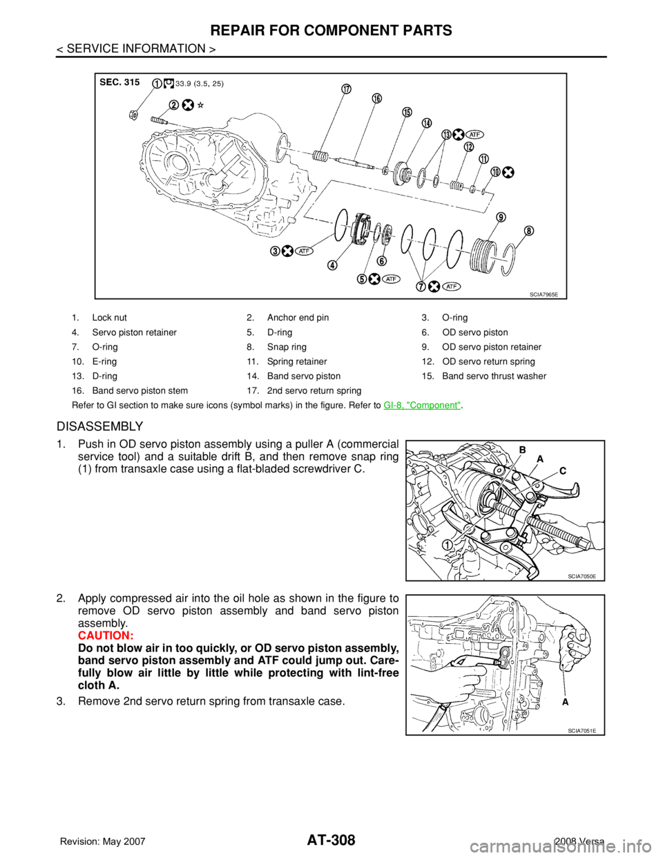
1. Push in OD servo piston assembly using a puller A (commercial
service tool) and a suitable drift B, and then remove snap ring
(1) from transaxle case using a flat-bladed screwdriver C.
2. Apply compressed air into the oil hole as shown in the figure to
remove OD servo piston assembly and band servo piston
assembly.
CAUTION:
Do not blow air in too quickly, or OD servo piston assembly,
band servo piston assembly and ATF could jump out. Care-
fully blow air little by little while protecting with lint-free
cloth A.
3. Remove 2nd servo return spring from transaxle case.
1. Lock nut 2. Anchor end pin 3. O-ring
4. Servo piston retainer 5. D-ring 6. OD servo piston
7. O-ring 8. Snap ring 9. OD servo piston retainer
10. E-ring 11. Spring retainer12. OD servo return spring
13. D-ring 14. Band servo piston 15. Band servo thrust washer
16. Band servo piston stem 17. 2nd servo return spring
Refer to GI section to make sure icons (symbol marks) in the figure. Refer to GI-8, "
Component".
SCIA7965E
SCIA7050E
SCIA7051E
Page 324 of 2771
AT-312
< SERVICE INFORMATION >
REPAIR FOR COMPONENT PARTS
6. Install D-ring (1) to OD servo piston (2).
7. Install O-rings and to OD servo piston retainer.
(1): O-ring (small diameter)
(2): O-ring (medium diameter)
(3): O-ring (large diameter)
(4): OD servo piston retainer
8. Install OD servo piston (1) to OD servo piston retainer (2) fitting
the figure direction on it.
9. Install 2nd servo return spring (2) and band servo piston assem-
bly (3) to transaxle case (1).
10. Install OD servo piston assembly (2) to transaxle case (1).
SCIA7053E
SCIA6492J
SCIA7057E
SCIA6310J
SCIA6010J
Page 325 of 2771
REPAIR FOR COMPONENT PARTS
AT-313
< SERVICE INFORMATION >
D
E
F
G
H
I
J
K
L
MA
B
AT
N
O
P
11. Push in OD servo piston assembly using a puller A (commercial
service tool) and a suitable drift B, and install snap ring (1) to
transaxle case using a flat-bladed screwdriver C.
Final DriveINFOID:0000000001703390
COMPONENTS
DISASSEMBLY
1. Remove final gear (1) from differential case (2).
SCIA7050E
1. Pinion mate gear 2. Pinion mate gear thrust washer 3. Pinion mate shaft
4. Lock pin 5. Side gear 6. Side gear thrust washer
7. Differential side bearing 8. Speedometer drive gear 9. Differential case
10. Final gear 11. Differential side bearing 12. Differential side bearing adjusting
shim
Refer to GI section to make sure icons (symbol marks) in the figure. Refer to GI-8, "
Component".
SCIA7962E
SCIA8003E