2008 NISSAN TIIDA Transaxle Assembly
[x] Cancel search: Transaxle AssemblyPage 144 of 2771
AT-132
< SERVICE INFORMATION >
DTC P0745 LINE PRESSURE SOLENOID VALVE
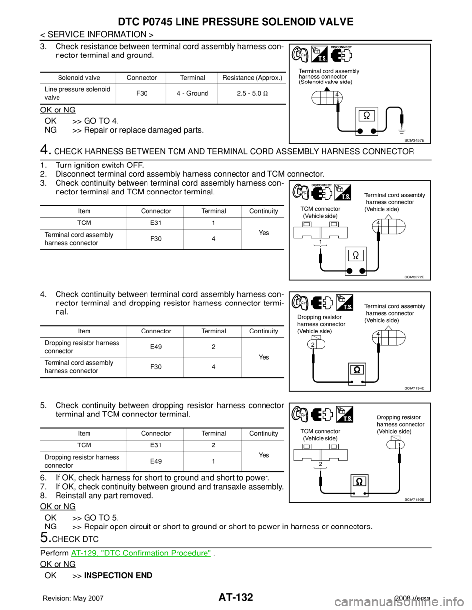
3. Check resistance between terminal cord assembly harness con-
nector terminal and ground.
OK or NG
OK >> GO TO 4.
NG >> Repair or replace damaged parts.
4. CHECK HARNESS BETWEEN TCM AND TERMINAL CORD ASSEMBLY HARNESS CONNECTOR
1. Turn ignition switch OFF.
2. Disconnect terminal cord assembly harness connector and TCM connector.
3. Check continuity between terminal cord assembly harness con-
nector terminal and TCM connector terminal.
4. Check continuity between terminal cord assembly harness con-
nector terminal and dropping resistor harness connector termi-
nal.
5. Check continuity between dropping resistor harness connector
terminal and TCM connector terminal.
6. If OK, check harness for short to ground and short to power.
7. If OK, check continuity between ground and transaxle assembly.
8. Reinstall any part removed.
OK or NG
OK >> GO TO 5.
NG >> Repair open circuit or short to ground or short to power in harness or connectors.
5.CHECK DTC
Perform AT-129, "
DTC Confirmation Procedure" .
OK or NG
OK >>INSPECTION END
Solenoid valve Connector Terminal Resistance (Approx.)
Line pressure solenoid
valveF30 4 - Ground 2.5 - 5.0 Ω
SCIA3457E
Item Connector Terminal Continuity
TCM E31 1
Ye s
Terminal cord assembly
harness connectorF30 4
SCIA3272E
Item Connector Terminal Continuity
Dropping resistor harness
connectorE49 2
Ye s
Terminal cord assembly
harness connectorF30 4
SCIA7194E
Item Connector Terminal Continuity
TCM E31 2
Ye s
Dropping resistor harness
connectorE49 1
SCIA7195E
Page 149 of 2771
DTC P0750 SHIFT SOLENOID VALVE A
AT-137
< SERVICE INFORMATION >
D
E
F
G
H
I
J
K
L
MA
B
AT
N
O
P
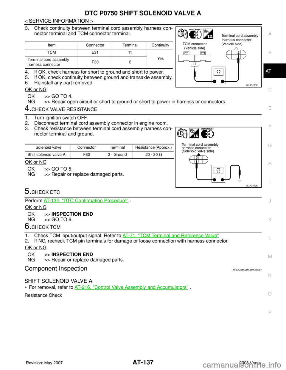
3. Check continuity between terminal cord assembly harness con-
nector terminal and TCM connector terminal.
4. If OK, check harness for short to ground and short to power.
5. If OK, check continuity between ground and transaxle assembly.
6. Reinstall any part removed.
OK or NG
OK >> GO TO 4.
NG >> Repair open circuit or short to ground or short to power in harness or connectors.
4.CHECK VALVE RESISTANCE
1. Turn ignition switch OFF.
2. Disconnect terminal cord assembly connector in engine room.
3. Check resistance between terminal cord assembly harness con-
nector terminal and ground.
OK or NG
OK >> GO TO 5.
NG >> Repair or replace damaged parts.
5.CHECK DTC
Perform AT-134, "
DTC Confirmation Procedure" .
OK or NG
OK >>INSPECTION END
NG >> GO TO 6.
6.CHECK TCM
1. Check TCM input/output signal. Refer to AT-71, "
TCM Terminal and Reference Value" .
2. If NG, recheck TCM pin terminals for damage or loose connection with harness connector.
OK or NG
OK >>INSPECTION END
NG >> Repair or replace damaged parts.
Component InspectionINFOID:0000000001703281
SHIFT SOLENOID VALVE A
• For removal, refer to AT-216, "Control Valve Assembly and Accumulators" .
Resistance Check
Item Connector Terminal Continuity
TCM E31 11
Ye s
Terminal cord assembly
harness connectorF30 2
SCIA3250E
Solenoid valve Connector Terminal Resistance (Approx.)
Shift solenoid valve A F30 2 - Ground 20 - 30 Ω
SCIA3453E
Page 154 of 2771
AT-142
< SERVICE INFORMATION >
DTC P0755 SHIFT SOLENOID VALVE B
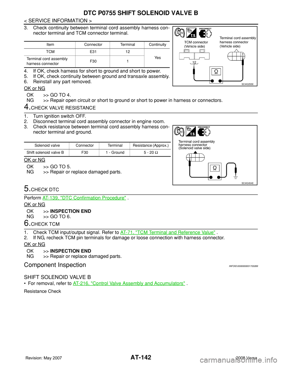
3. Check continuity between terminal cord assembly harness con-
nector terminal and TCM connector terminal.
4. If OK, check harness for short to ground and short to power.
5. If OK, check continuity between ground and transaxle assembly.
6. Reinstall any part removed.
OK or NG
OK >> GO TO 4.
NG >> Repair open circuit or short to ground or short to power in harness or connectors.
4.CHECK VALVE RESISTANCE
1. Turn ignition switch OFF.
2. Disconnect terminal cord assembly connector in engine room.
3. Check resistance between terminal cord assembly harness con-
nector terminal and ground.
OK or NG
OK >> GO TO 5.
NG >> Repair or replace damaged parts.
5.CHECK DTC
Perform AT-139, "
DTC Confirmation Procedure" .
OK or NG
OK >>INSPECTION END
NG >> GO TO 6.
6.CHECK TCM
1. Check TCM input/output signal. Refer to AT-71, "
TCM Terminal and Reference Value" .
2. If NG, recheck TCM pin terminals for damage or loose connection with harness connector.
OK or NG
OK >>INSPECTION END
NG >> Repair or replace damaged parts.
Component InspectionINFOID:0000000001703289
SHIFT SOLENOID VALVE B
• For removal, refer to AT-216, "Control Valve Assembly and Accumulators" .
Resistance Check
Item Connector Terminal Continuity
TCM E31 12
Ye s
Terminal cord assembly
harness connectorF30 1
SCIA3255E
Solenoid valve Connector Terminal Resistance (Approx.)
Shift solenoid valve B F30 1 - Ground 5 - 20 Ω
SCIA3454E
Page 159 of 2771
DTC P1760 OVERRUN CLUTCH SOLENOID VALVE
AT-147
< SERVICE INFORMATION >
D
E
F
G
H
I
J
K
L
MA
B
AT
N
O
P
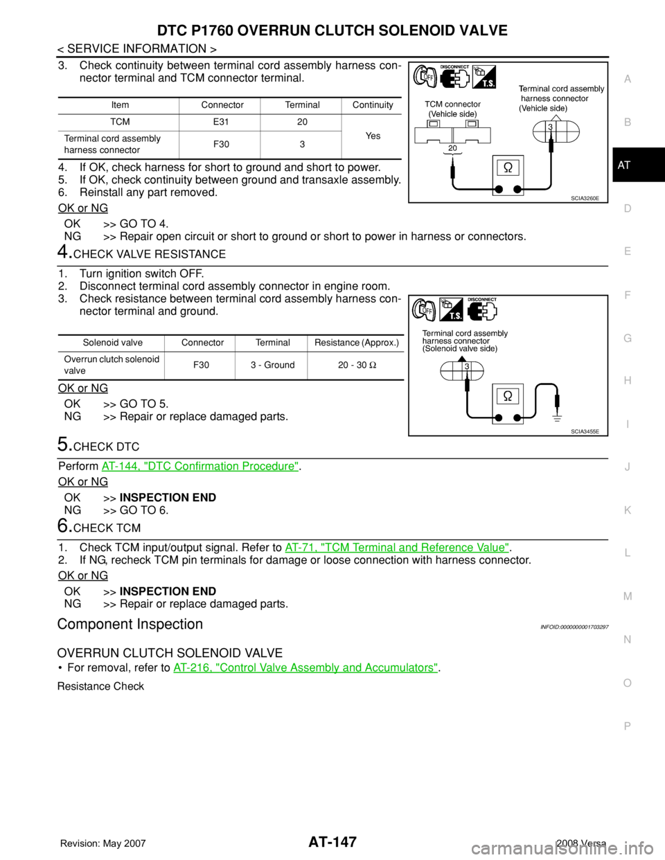
3. Check continuity between terminal cord assembly harness con-
nector terminal and TCM connector terminal.
4. If OK, check harness for short to ground and short to power.
5. If OK, check continuity between ground and transaxle assembly.
6. Reinstall any part removed.
OK or NG
OK >> GO TO 4.
NG >> Repair open circuit or short to ground or short to power in harness or connectors.
4.CHECK VALVE RESISTANCE
1. Turn ignition switch OFF.
2. Disconnect terminal cord assembly connector in engine room.
3. Check resistance between terminal cord assembly harness con-
nector terminal and ground.
OK or NG
OK >> GO TO 5.
NG >> Repair or replace damaged parts.
5.CHECK DTC
Perform AT-144, "
DTC Confirmation Procedure".
OK or NG
OK >>INSPECTION END
NG >> GO TO 6.
6.CHECK TCM
1. Check TCM input/output signal. Refer to AT-71, "
TCM Terminal and Reference Value".
2. If NG, recheck TCM pin terminals for damage or loose connection with harness connector.
OK or NG
OK >>INSPECTION END
NG >> Repair or replace damaged parts.
Component InspectionINFOID:0000000001703297
OVERRUN CLUTCH SOLENOID VALVE
• For removal, refer to AT-216, "Control Valve Assembly and Accumulators".
Resistance Check
Item Connector Terminal Continuity
TCM E31 20
Ye s
Terminal cord assembly
harness connectorF30 3
SCIA3260E
Solenoid valve Connector Terminal Resistance (Approx.)
Overrun clutch solenoid
valveF30 3 - Ground 20 - 30 Ω
SCIA3455E
Page 167 of 2771
DTC BATT/FLUID TEMP SEN (A/T FLUID TEMP SENSOR CIRCUIT AND TCM
POWER SOURCE)
AT-155
< SERVICE INFORMATION >
D
E
F
G
H
I
J
K
L
MA
B
AT
N
O
P
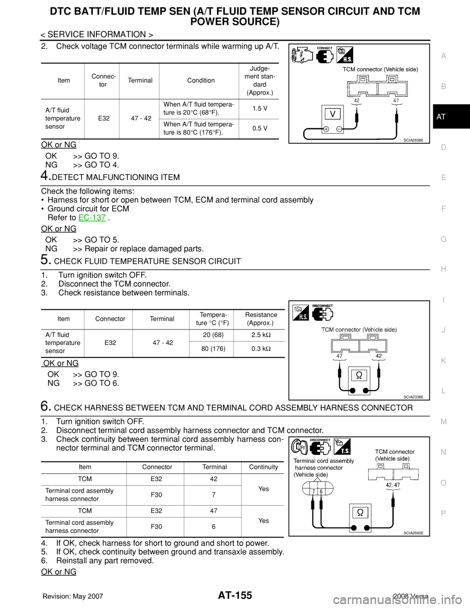
2. Check voltage TCM connector terminals while warming up A/T.
OK or NG
OK >> GO TO 9.
NG >> GO TO 4.
4.DETECT MALFUNCTIONING ITEM
Check the following items:
• Harness for short or open between TCM, ECM and terminal cord assembly
• Ground circuit for ECM
Refer to EC-137
.
OK or NG
OK >> GO TO 5.
NG >> Repair or replace damaged parts.
5. CHECK FLUID TEMPERATURE SENSOR CIRCUIT
1. Turn ignition switch OFF.
2. Disconnect the TCM connector.
3. Check resistance between terminals.
OK or NG
OK >> GO TO 9.
NG >> GO TO 6.
6. CHECK HARNESS BETWEEN TCM AND TERMINAL CORD ASSEMBLY HARNESS CONNECTOR
1. Turn ignition switch OFF.
2. Disconnect terminal cord assembly harness connector and TCM connector.
3. Check continuity between terminal cord assembly harness con-
nector terminal and TCM connector terminal.
4. If OK, check harness for short to ground and short to power.
5. If OK, check continuity between ground and transaxle assembly.
6. Reinstall any part removed.
OK or NG
Item Connec-
torTerminal ConditionJudge-
ment stan-
dard
(Approx.)
A/T fluid
temperature
sensor E32 47 - 42When A/T fluid tempera-
ture is 20°C (68°F).1.5 V
When A/T fluid tempera-
ture is 80°C (176°F).0.5 V
SCIA2658E
Item Connector Terminal Te m p e r a -
ture °C (°F) Resistance
(Approx.)
A/T fluid
temperature
sensor E32 47 - 42 20 (68) 2.5 kΩ
80 (176) 0.3 kΩ
SCIA2338E
Item Connector Terminal Continuity
TCM E32 42
Ye s
Terminal cord assembly
harness connectorF30 7
TCM E32 47
Ye s
Terminal cord assembly
harness connectorF30 6
SCIA2660E
Page 212 of 2771
AT-200
< SERVICE INFORMATION >
TROUBLE DIAGNOSIS FOR SYMPTOMS
- Shift valve A
- Overrun clutch solenoid valve
3. Disassemble A/T. Refer to AT-240, "
Disassembly" .
4. Check the following.
- Overrun clutch assembly. Refer to AT-288, "
Forward and Overrun Clutches" .
- Low & reverse brake assembly. Refer to AT-295, "
Low & Reverse Brake" .
OK or NG
OK >> GO TO 10.
NG >> Repair or replace damaged parts.
10.CHECK SYMPTOM
Check again. Refer to AT-59, "
Cruise Test - Part 3" .
OK or NG
OK >>INSPECTION END
NG >> GO TO 11.
11 .CHECK TCM
1. Check TCM input/output signals. Refer to AT-71, "
TCM Terminal and Reference Value" .
2. If NG, recheck TCM pin terminals for damage or loose connection with harness connector.
OK or NG
OK >> INSPECTION END
NG >> Repair or replace damaged parts.
TCM Self-Diagnosis Does Not ActivateINFOID:0000000001703354
SYMPTOM:
OD OFF indicator lamp does not come on in TCM self-diagnostic procedure even if the lamp circuit is
good.
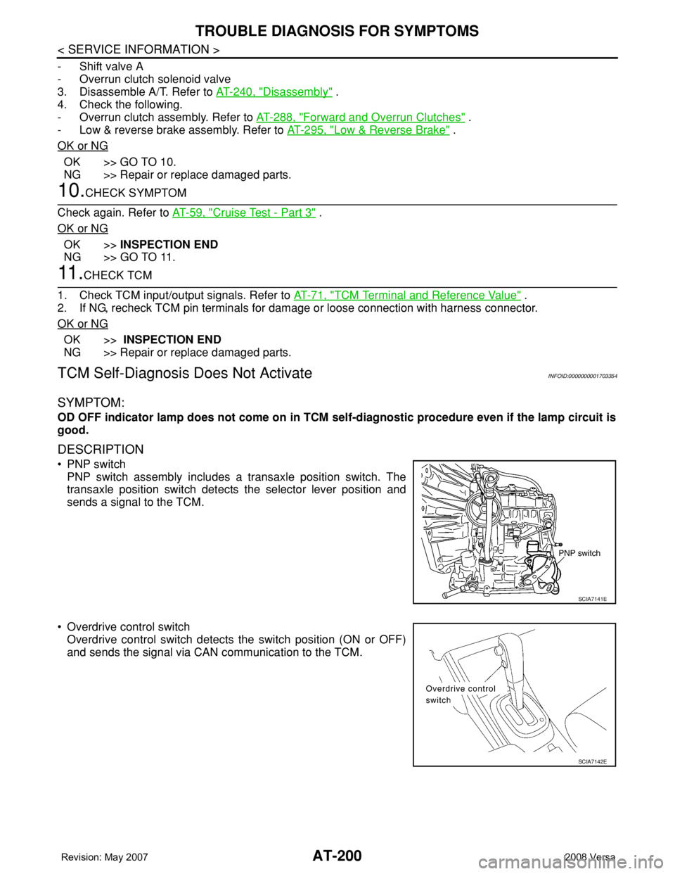
DESCRIPTION
• PNP switch
PNP switch assembly includes a transaxle position switch. The
transaxle position switch detects the selector lever position and
sends a signal to the TCM.
• Overdrive control switch
Overdrive control switch detects the switch position (ON or OFF)
and sends the signal via CAN communication to the TCM.
SCIA7141E
SCIA7142E
Page 219 of 2771

SHIFT CONTROL SYSTEM
AT-207
< SERVICE INFORMATION >
D
E
F
G
H
I
J
K
L
MA
B
AT
N
O
P
1. Place the selector lever knob (1) in “N” position.
2. Slide knob cover (2) downward.
3. Pull out lock pin (3) from selector lever knob (1).
4. Remove selector lever knob (1) and knob cover (2) as a set from
selector lever.
CAUTION:
Do not push selector button.
INSTALLATION
1. Insert lock pin (1) to selector lever knob (2).
2. Install knob cover (3) to selector lever knob (2).
3. Place the selector lever in “N” position.
4. Install selector lever knob over selector lever until a click is felt.
CAUTION:
• Do not tilt selector lever knob when installing. Install it
straight, and do not tap or apply any shock to install it.
• Do not push selector button.
Adjustment of A/T PositionINFOID:0000000001703359
Move selector lever from “P” position to “1” position. You should be able to feel the detents in each position. If
the detents cannot be felt or if the position indicator is improperly aligned, the control cable needs adjustment.
CAUTION:
Make sure that parking brake is applied before adjustment.
1. Remove the air duct assembly. Refer to EM-16
.
2. Remove the control cable nut (A) and control cable (1) and
place the manual lever (2) in the "P' position.
3. Place selector lever in “P” position.
4. Hold control cable (1) at the end and pull it with a force of 9.8 N
(approximately 1 kg, 2.2 lb). Release the control cable and tem-
porarily tighten control cable nut (A).
5. Tighten control cable nut (A) to the specified torque.
CAUTION:
Secure manual lever when tightening nut.
6. Move selector lever from “P” to “1” position again. Make sure that selector lever moves smoothly.
7. Check A/T position. Refer to AT-207, "
Checking of A/T Position".
8. Install air duct assembly. Refer to EM-16
.
Checking of A/T PositionINFOID:0000000001703360
1. Place selector lever in “P” position, and turn ignition switch ON (Do not start engine).
2. Make sure selector lever can be shifted to other than “P” position when brake pedal is depressed. Also
make sure selector lever can be shifted from “P” position only when brake pedal is depressed.
3. Move selector lever and check for excessive effort, sticking, noise or rattle.
4. Confirm selector lever stops at each position with the feel of engagement when it is moved through all the
positions. Check whether or not the actual position selector lever is in matches the position shown by the
shift position indicator and the transaxle.
SCIA6971E
SCIA6972E
Control cable nut : Refer to AT-203, "Control De-
vice Removal and Installation".WCIA0635E
Page 229 of 2771
ON-VEHICLE SERVICE
AT-217
< SERVICE INFORMATION >
D
E
F
G
H
I
J
K
L
MA
B
AT
N
O
P
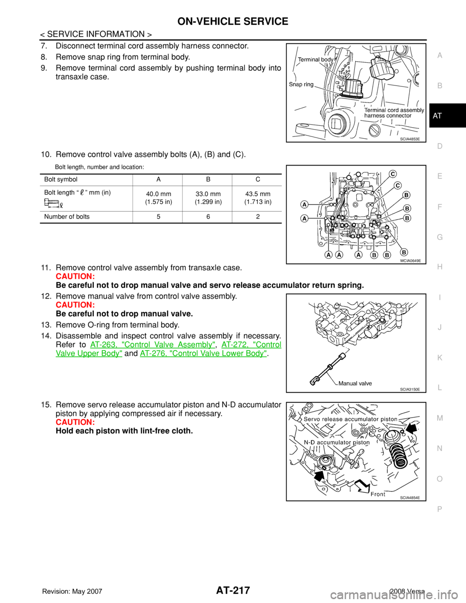
7. Disconnect terminal cord assembly harness connector.
8. Remove snap ring from terminal body.
9. Remove terminal cord assembly by pushing terminal body into
transaxle case.
10. Remove control valve assembly bolts (A), (B) and (C).
Bolt length, number and location:
11. Remove control valve assembly from transaxle case.
CAUTION:
Be careful not to drop manual valve and servo release accumulator return spring.
12. Remove manual valve from control valve assembly.
CAUTION:
Be careful not to drop manual valve.
13. Remove O-ring from terminal body.
14. Disassemble and inspect control valve assembly if necessary.
Refer to AT-263, "
Control Valve Assembly", AT-272, "Control
Valve Upper Body" and AT-276, "Control Valve Lower Body".
15. Remove servo release accumulator piston and N-D accumulator
piston by applying compressed air if necessary.
CAUTION:
Hold each piston with lint-free cloth.
SCIA4853E
Bolt symbol A B C
Bolt length “ ” mm (in)
40.0 mm
(1.575 in)33.0 mm
(1.299 in)43.5 mm
(1.713 in)
Number of bolts 5 6 2
WCIA0649E
SCIA3150E
SCIA4854E