2008 NISSAN TIIDA Fill Plug
[x] Cancel search: Fill PlugPage 21 of 2771
PRECAUTIONS
AT-9
< SERVICE INFORMATION >
D
E
F
G
H
I
J
K
L
MA
B
AT
N
O
P
• Before assembly, apply a coat of recommended ATF to all parts. Apply petroleum jelly to protect O-rings and
seals, or hold bearings and washers in place during assembly. Do not use grease.
• Extreme care should be taken to avoid damage to O-rings, seals and gaskets when assembling.
• Clean or replace ATF cooler if excessive foreign material is found in oil pan or clogging strainer. Refer to
Refer to .
• After overhaul, refill the A/T with new ATF.
• When the A/T drain plug is removed, only some of the fluid is drained. Old A/T fluid will remain in torque con-
verter and ATF cooling system.
Always follow the procedures under “Changing A/T Fluid” in the AT section when changing A/T fluid. Refer to
MA-22, "
Changing A/T Fluid", MA-22, "Checking A/T Fluid".
Service Notice or PrecautionINFOID:0000000001703155
ATF COOLER SERVICE
If A/T fluid contains frictional material (clutches, bands, etc.), or if an A/T is repaired, overhauled, or replaced,
inspect and clean the A/T oil cooler mounted in the radiator or replace the radiator. Flush cooler lines using
cleaning solvent and compressed air after repair. Check Service Bulletins for latest A/T oil cooler cleaning pro-
cedure. For radiator replacement, refer to Refer to CO-11
.
TORQUE CONVERTER SERVICE
The torque converter should be replaced under any of the following conditions:
• External leaks in the hub weld area.
• Converter hub is scored or damaged.
• Converter pilot is broken, damaged or fits poorly into crankshaft.
• Steel particles are found after flushing the cooler and cooler lines.
• Pump is damaged or steel particles are found in the converter.
• Vehicle has TCC shudder and/or no TCC apply. Replace only after all hydraulic and electrical diagnoses
have been made. (Converter clutch material may be glazed.)
• Converter is contaminated with engine coolant containing antifreeze.
• Internal malfunction of stator roller clutch.
• Heavy clutch debris due to overheating (blue converter).
• Steel particles or clutch lining material found in fluid filter or on magnet when no internal parts in unit are
worn or damaged — indicates that lining material came from converter.
The torque converter should not be replaced if:
• The fluid has an odor, is discolored, and there is no evidence of metal or clutch facing particles.
• The threads in one or more of the converter bolt holes are damaged.
• A/T malfunction did not display evidence of damaged or worn internal parts, steel particles or clutch plate lin-
ing material in unit and inside the fluid filter.
• Vehicle has been exposed to high mileage (only). The exception may be where the torque converter clutch
dampener plate lining has seen excess wear by vehicles operated in heavy and/or constant traffic, such as
taxi, delivery or police use.
OBD-II SELF-DIAGNOSIS
• A/T self-diagnosis is performed by the TCM in combination with the ECM. The results can be read through
the blinking pattern of the OD OFF indicator lamp or the malfunction indicator lamp (MIL). Refer to the table
on AT-78, "
Diagnosis Procedure without CONSULT-III" for the indicator used to display each self-diagnostic
result.
• The self-diagnostic results indicated by the MIL are automatically stored in both the ECM and TCM memo-
ries.
Always perform the procedure “HOW TO ERASE DTC” on AT-36, "
OBD-II Diagnostic Trouble Code
(DTC)" to complete the repair and avoid unnecessary blinking of the MIL.
• The following self-diagnostic items can be detected using ECM self-diagnostic results mode* only when the
OD OFF indicator lamp does not indicate any malfunctions.
-PNP switch
- A/T 1st, 2nd, 3rd, or 4th gear function
*: For details of OBD-II, refer to AT- 3 6
.
•Certain systems and components, especially those related to OBD, may use a new style slide-lock-
ing type harness connector.
For description and how to disconnect, refer to PG-65
.
Page 27 of 2771
A/T FLUID
AT-15
< SERVICE INFORMATION >
D
E
F
G
H
I
J
K
L
MA
B
AT
N
O
P
A/T FLUID
Checking A/T FluidINFOID:0000000001703158
1. Warm up engine.
2. Check for A/T fluid leakage.
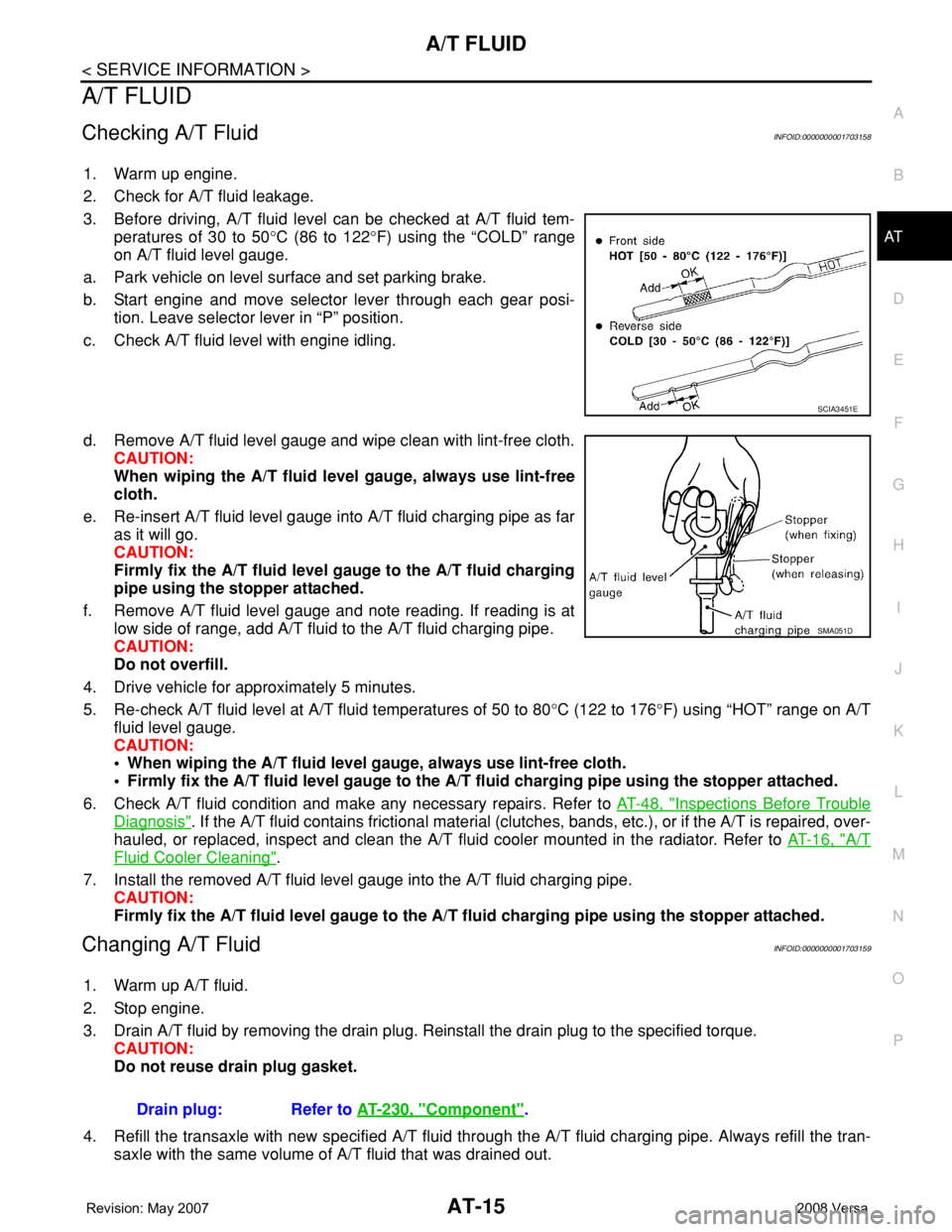
3. Before driving, A/T fluid level can be checked at A/T fluid tem-
peratures of 30 to 50°C (86 to 122°F) using the “COLD” range
on A/T fluid level gauge.
a. Park vehicle on level surface and set parking brake.
b. Start engine and move selector lever through each gear posi-
tion. Leave selector lever in “P” position.
c. Check A/T fluid level with engine idling.
d. Remove A/T fluid level gauge and wipe clean with lint-free cloth.
CAUTION:
When wiping the A/T fluid level gauge, always use lint-free
cloth.
e. Re-insert A/T fluid level gauge into A/T fluid charging pipe as far
as it will go.
CAUTION:
Firmly fix the A/T fluid level gauge to the A/T fluid charging
pipe using the stopper attached.
f. Remove A/T fluid level gauge and note reading. If reading is at
low side of range, add A/T fluid to the A/T fluid charging pipe.
CAUTION:
Do not overfill.
4. Drive vehicle for approximately 5 minutes.
5. Re-check A/T fluid level at A/T fluid temperatures of 50 to 80°C (122 to 176°F) using “HOT” range on A/T
fluid level gauge.
CAUTION:
• When wiping the A/T fluid level gauge, always use lint-free cloth.
• Firmly fix the A/T fluid level gauge to the A/T fluid charging pipe using the stopper attached.
6. Check A/T fluid condition and make any necessary repairs. Refer to AT-48, "
Inspections Before Trouble
Diagnosis". If the A/T fluid contains frictional material (clutches, bands, etc.), or if the A/T is repaired, over-
hauled, or replaced, inspect and clean the A/T fluid cooler mounted in the radiator. Refer to AT-16, "
A/T
Fluid Cooler Cleaning".
7. Install the removed A/T fluid level gauge into the A/T fluid charging pipe.
CAUTION:
Firmly fix the A/T fluid level gauge to the A/T fluid charging pipe using the stopper attached.
Changing A/T FluidINFOID:0000000001703159
1. Warm up A/T fluid.
2. Stop engine.
3. Drain A/T fluid by removing the drain plug. Reinstall the drain plug to the specified torque.
CAUTION:
Do not reuse drain plug gasket.
4. Refill the transaxle with new specified A/T fluid through the A/T fluid charging pipe. Always refill the tran-
saxle with the same volume of A/T fluid that was drained out.
SCIA3451E
SMA051D
Drain plug: Refer to AT-230, "Component".
Page 825 of 2771
CO-8
< SERVICE INFORMATION >
ENGINE COOLANT
ENGINE COOLANT
InspectionINFOID:0000000001702529
LEVEL CHECK
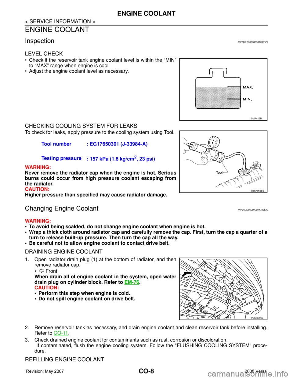
• Check if the reservoir tank engine coolant level is within the “MIN”
to “MAX” range when engine is cool.
• Adjust the engine coolant level as necessary.
CHECKING COOLING SYSTEM FOR LEAKS
To check for leaks, apply pressure to the cooling system using Tool.
WARNING:
Never remove the radiator cap when the engine is hot. Serious
burns could occur from high pressure coolant escaping from
the radiator.
CAUTION:
Higher pressure than specified may cause radiator damage.
Changing Engine CoolantINFOID:0000000001702530
WARNING:
• To avoid being scalded, do not change engine coolant when engine is hot.
• Wrap a thick cloth around radiator cap and carefully remove the cap. First, turn the cap a quarter of a
turn to release built-up pressure. Then turn the cap all the way.
• Be careful not to allow engine coolant to contact drive belt.
DRAINING ENGINE COOLANT
1. Open radiator drain plug (1) at the bottom of radiator, and then
remove radiator cap.
• Front
When drain all of engine coolant in the system, open water
drain plug on cylinder block. Refer to EM-76
.
CAUTION:
• Perform this step when engine is cold.
• Do not spill engine coolant on drive belt.
2. Remove reservoir tank as necessary, and drain engine coolant and clean reservoir tank before installing.
Refer to CO-11
.
3. Check drained engine coolant for contaminants such as rust, corrosion or discoloration.
If contaminated, flush the engine cooling system. Follow the "FLUSHING COOLING SYSTEM" proce-
dure.
REFILLING ENGINE COOLANT
SMA412B
Tool number : EG17650301 (J-33984-A)
Testing pressure
: 157 kPa (1.6 kg/cm
2, 23 psi)
WBIA0568E
PBIC3799E
Page 826 of 2771
ENGINE COOLANT
CO-9
< SERVICE INFORMATION >
C
D
E
F
G
H
I
J
K
L
MA
CO
N
P O
1. Install reservoir tank if removed. Refer to CO-11.
2. Install radiator drain plug.
•If water drain plug on cylinder block is removed, close and tighten it. Refer to EM-76
.
CAUTION:
Be sure to clean radiator drain plug and install with new O-ring. Refer to CO-11, "
Component".
3. Make sure that each hose clamp has been firmly tightened.
4. Remove air duct assembly. Refer to EM-16
.
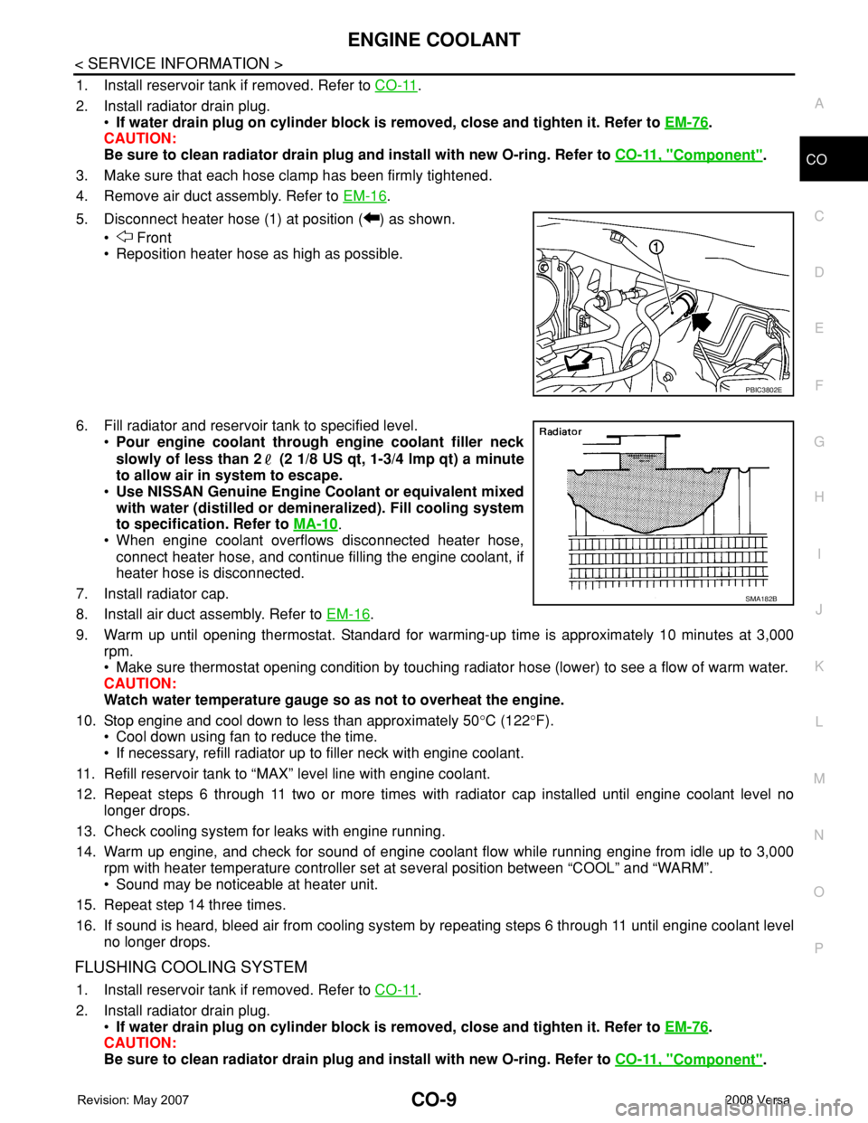
5. Disconnect heater hose (1) at position ( ) as shown.
• Front
• Reposition heater hose as high as possible.
6. Fill radiator and reservoir tank to specified level.
•Pour engine coolant through engine coolant filler neck
slowly of less than 2 (2 1/8 US qt, 1-3/4 lmp qt) a minute
to allow air in system to escape.
•Use NISSAN Genuine Engine Coolant or equivalent mixed
with water (distilled or demineralized). Fill cooling system
to specification. Refer to MA-10
.
• When engine coolant overflows disconnected heater hose,
connect heater hose, and continue filling the engine coolant, if
heater hose is disconnected.
7. Install radiator cap.
8. Install air duct assembly. Refer to EM-16
.
9. Warm up until opening thermostat. Standard for warming-up time is approximately 10 minutes at 3,000
rpm.
• Make sure thermostat opening condition by touching radiator hose (lower) to see a flow of warm water.
CAUTION:
Watch water temperature gauge so as not to overheat the engine.
10. Stop engine and cool down to less than approximately 50°C (122°F).
• Cool down using fan to reduce the time.
• If necessary, refill radiator up to filler neck with engine coolant.
11. Refill reservoir tank to “MAX” level line with engine coolant.
12. Repeat steps 6 through 11 two or more times with radiator cap installed until engine coolant level no
longer drops.
13. Check cooling system for leaks with engine running.
14. Warm up engine, and check for sound of engine coolant flow while running engine from idle up to 3,000
rpm with heater temperature controller set at several position between “COOL” and “WARM”.
• Sound may be noticeable at heater unit.
15. Repeat step 14 three times.
16. If sound is heard, bleed air from cooling system by repeating steps 6 through 11 until engine coolant level
no longer drops.
FLUSHING COOLING SYSTEM
1. Install reservoir tank if removed. Refer to CO-11.
2. Install radiator drain plug.
•If water drain plug on cylinder block is removed, close and tighten it. Refer to EM-76
.
CAUTION:
Be sure to clean radiator drain plug and install with new O-ring. Refer to CO-11, "
Component".
PBIC3802E
SMA182B
Page 1831 of 2771
FUEL TANK
FL-11
< SERVICE INFORMATION >
C
D
E
F
G
H
I
J
K
L
MA
FL
N
P O
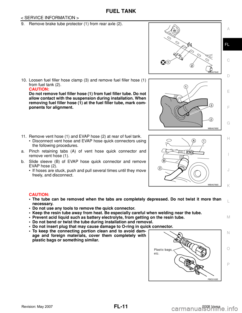
9. Remove brake tube protector (1) from rear axle (2).
10. Loosen fuel filler hose clamp (3) and remove fuel filler hose (1)
from fuel tank (2).
CAUTION:
Do not remove fuel filler hose (1) from fuel filler tube. Do not
allow contact with the suspension during installation. When
removing fuel filler hose (1) at the fuel filler tube, mark com-
ponents for alignment.
11. Remove vent hose (1) and EVAP hose (2) at rear of fuel tank.
• Disconnect vent hose and EVAP hose quick connectors using
the following procedures.
a. Pinch retaining tabs (A) of vent hose quick connector and
remove vent hose (1).
b. Slide sleeve (B) of EVAP hose quick connector and remove
EVAP hose (2).
• If hoses are stuck, push and pull several times until they move
freely, and disconnect.
CAUTION:
• The tube can be removed when the tabs are completely depressed. Do not twist it more than
necessary.
• Do not use any tools to remove the quick connector.
• Keep the resin tube away from heat. Be especially careful when welding near the tube.
• Prevent acid liquid such as battery electrolyte, from getting on the resin tube.
• Do not bend or twist the tube during installation and removal.
• Do not insert plug that may cause damage to O-ring in quick connector.
• To keep the connecting portion clean and to avoid dam-
age and foreign materials, cover them completely with
plastic bags or something similar.
WBIA0764E
WBIA0765E
WBIA0766E
PBIC0163E
Page 2258 of 2771
LU-8
< SERVICE INFORMATION >
ENGINE OIL
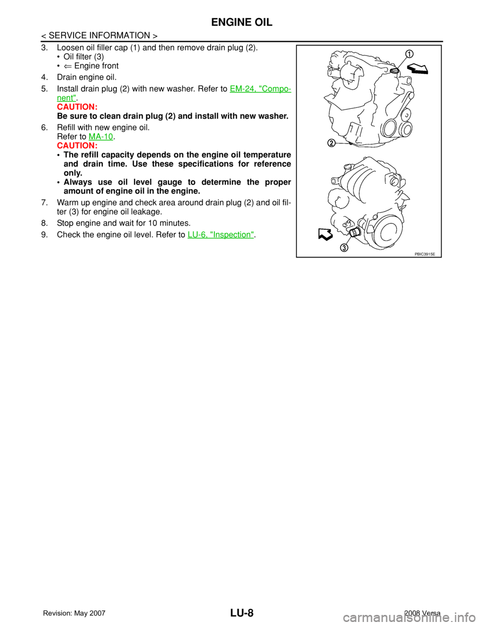
3. Loosen oil filler cap (1) and then remove drain plug (2).
• Oil filter (3)
•⇐ Engine front
4. Drain engine oil.
5. Install drain plug (2) with new washer. Refer to EM-24, "
Compo-
nent".
CAUTION:
Be sure to clean drain plug (2) and install with new washer.
6. Refill with new engine oil.
Refer to MA-10
.
CAUTION:
• The refill capacity depends on the engine oil temperature
and drain time. Use these specifications for reference
only.
• Always use oil level gauge to determine the proper
amount of engine oil in the engine.
7. Warm up engine and check area around drain plug (2) and oil fil-
ter (3) for engine oil leakage.
8. Stop engine and wait for 10 minutes.
9. Check the engine oil level. Refer to LU-6, "
Inspection".
PBIC3915E
Page 2263 of 2771
PREPARATION
MA-3
< SERVICE INFORMATION >
C
D
E
F
G
H
I
J
K
MA
B
MA
N
O
P
PREPARATION
Special Service ToolINFOID:0000000001704718
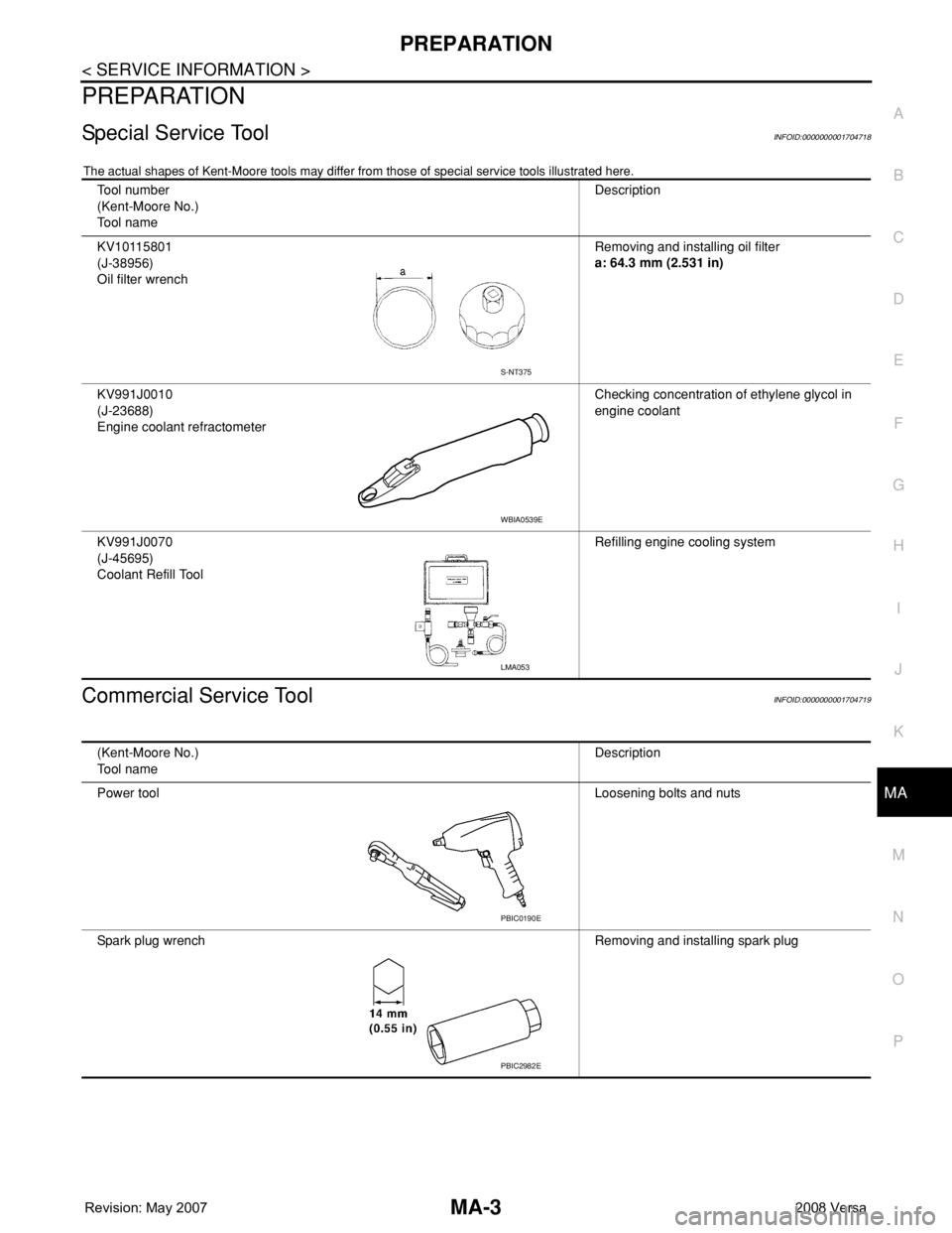
The actual shapes of Kent-Moore tools may differ from those of special service tools illustrated here.
Commercial Service ToolINFOID:0000000001704719
Tool number
(Kent-Moore No.)
Tool nameDescription
KV10115801
(J-38956)
Oil filter wrenchRemoving and installing oil filter
a: 64.3 mm (2.531 in)
KV991J0010
(J-23688)
Engine coolant refractometerChecking concentration of ethylene glycol in
engine coolant
KV991J0070
(J-45695)
Coolant Refill ToolRefilling engine cooling system
S-NT375
WBIA0539E
LMA053
(Kent-Moore No.)
Tool nameDescription
Power toolLoosening bolts and nuts
Spark plug wrench Removing and installing spark plug
PBIC0190E
PBIC2982E
Page 2273 of 2771
ENGINE MAINTENANCE
MA-13
< SERVICE INFORMATION >
C
D
E
F
G
H
I
J
K
MA
B
MA
N
O
P
2. Remove reservoir tank as necessary, and drain engine coolant and clean reservoir tank before installing.
Refer to CO-11
.
3. Check drained engine coolant for contaminants such as rust, corrosion or discoloration.
If contaminated, flush the engine cooling system. Refer to "FLUSHING COOLING SYSTEM" .
REFILLING ENGINE COOLANT
1. Install reservoir tank if removed. Refer to CO-11 .
2. Install radiator drain plug.
•If water drain plug on cylinder block is removed, close and tighten it. Refer to EM-76
.
CAUTION:
Be sure to clean radiator drain plug and install with new O-ring. Refer to CO-11, "
Component" .
3. Make sure that each hose clamp has been firmly tightened.
4. Remove air duct assembly. Refer to EM-16
.
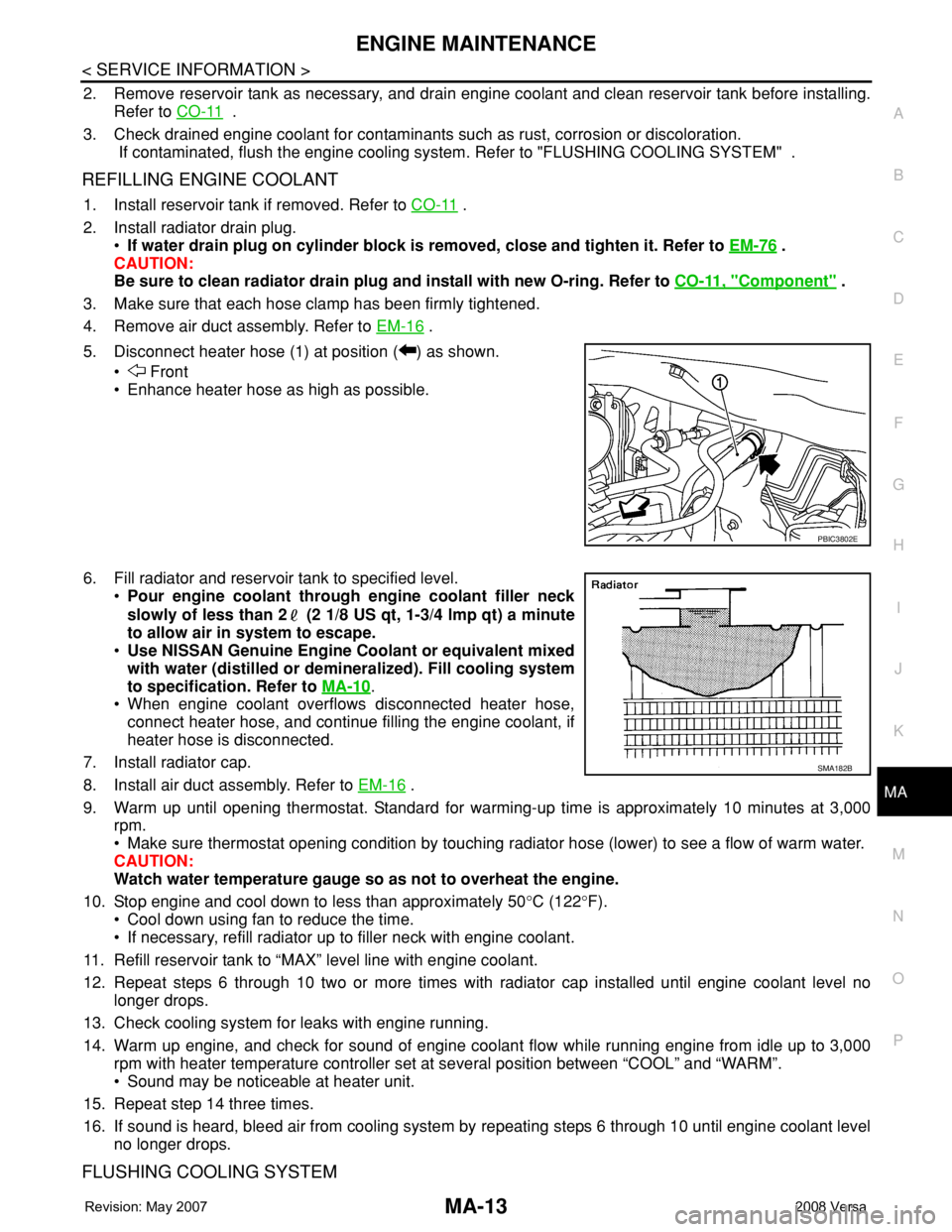
5. Disconnect heater hose (1) at position ( ) as shown.
• Front
• Enhance heater hose as high as possible.
6. Fill radiator and reservoir tank to specified level.
•Pour engine coolant through engine coolant filler neck
slowly of less than 2 (2 1/8 US qt, 1-3/4 lmp qt) a minute
to allow air in system to escape.
•Use NISSAN Genuine Engine Coolant or equivalent mixed
with water (distilled or demineralized). Fill cooling system
to specification. Refer to MA-10
.
• When engine coolant overflows disconnected heater hose,
connect heater hose, and continue filling the engine coolant, if
heater hose is disconnected.
7. Install radiator cap.
8. Install air duct assembly. Refer to EM-16
.
9. Warm up until opening thermostat. Standard for warming-up time is approximately 10 minutes at 3,000
rpm.
• Make sure thermostat opening condition by touching radiator hose (lower) to see a flow of warm water.
CAUTION:
Watch water temperature gauge so as not to overheat the engine.
10. Stop engine and cool down to less than approximately 50°C (122°F).
• Cool down using fan to reduce the time.
• If necessary, refill radiator up to filler neck with engine coolant.
11. Refill reservoir tank to “MAX” level line with engine coolant.
12. Repeat steps 6 through 10 two or more times with radiator cap installed until engine coolant level no
longer drops.
13. Check cooling system for leaks with engine running.
14. Warm up engine, and check for sound of engine coolant flow while running engine from idle up to 3,000
rpm with heater temperature controller set at several position between “COOL” and “WARM”.
• Sound may be noticeable at heater unit.
15. Repeat step 14 three times.
16. If sound is heard, bleed air from cooling system by repeating steps 6 through 10 until engine coolant level
no longer drops.
FLUSHING COOLING SYSTEM
PBIC3802E
SMA182B