Page 1644 of 2771
COWL TOP
EI-21
< ON-VEHICLE REPAIR >
C
D
E
F
G
H
J
K
L
MA
B
EI
N
O
P
COWL TOP
Removal and InstallationINFOID:0000000001704223
REMOVAL
1. Remove front wiper arm RH/LH from vehicle. Refer to WW-18, "Removal and Installation of Front Wiper
Arms".
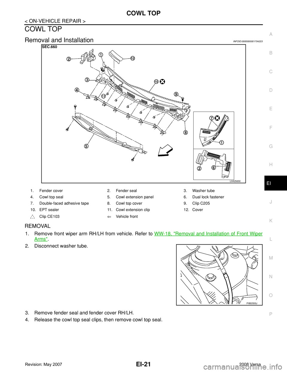
2. Disconnect washer tube.
3. Remove fender seal and fender cover RH/LH.
4. Release the cowl top seal clips, then remove cowl top seal.
LIIA2565E
1. Fender cover 2. Fender seal 3. Washer tube
4. Cowl top seal 5. Cowl extension panel 6. Dual lock fastener
7. Double-faced adhesive tape 8. Cowl top cover 9. Clip C205
10. EPT sealer 11. Cowl extension clip 12. Cover
Clip CE103⇐Vehicle front
PIIB2555J
Page 1645 of 2771
EI-22
< ON-VEHICLE REPAIR >
COWL TOP
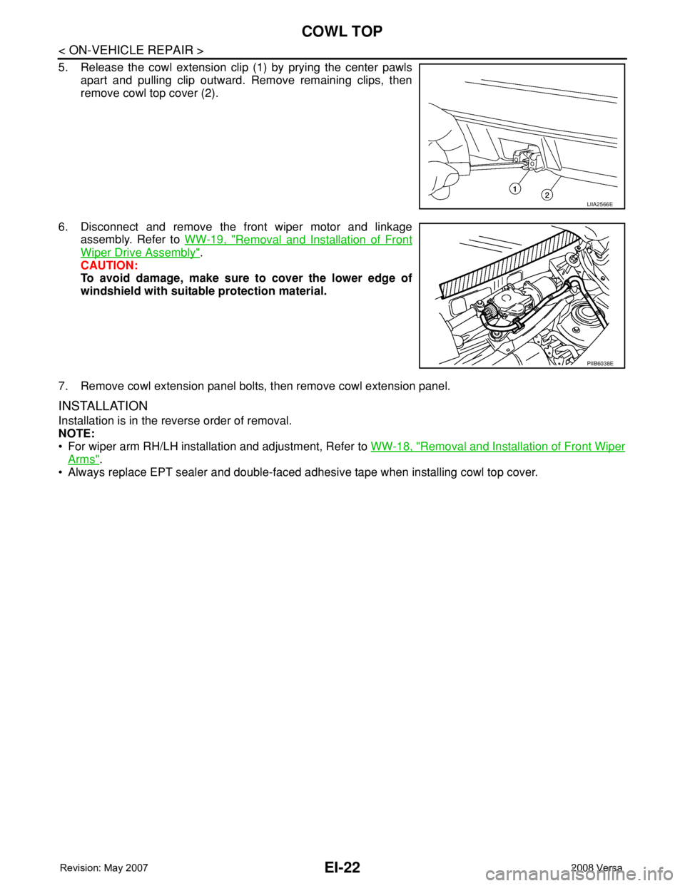
5. Release the cowl extension clip (1) by prying the center pawls
apart and pulling clip outward. Remove remaining clips, then
remove cowl top cover (2).
6. Disconnect and remove the front wiper motor and linkage
assembly. Refer to WW-19, "
Removal and Installation of Front
Wiper Drive Assembly".
CAUTION:
To avoid damage, make sure to cover the lower edge of
windshield with suitable protection material.
7. Remove cowl extension panel bolts, then remove cowl extension panel.
INSTALLATION
Installation is in the reverse order of removal.
NOTE:
• For wiper arm RH/LH installation and adjustment, Refer to WW-18, "
Removal and Installation of Front Wiper
Arms".
• Always replace EPT sealer and double-faced adhesive tape when installing cowl top cover.
LIIA2566E
PIIB6038E
Page 1845 of 2771
COIL SPRING AND STRUT
FSU-11
< SERVICE INFORMATION >
C
D
F
G
H
I
J
K
L
MA
B
FSU
N
O
P
COIL SPRING AND STRUT
Removal and InstallationINFOID:0000000001703725
REMOVAL
1. Remove cowl top panel. Refer to EI-21 .
2. Remove front tires using power tool.
3. Remove harness of wheel sensor from strut assembly. Refer to BRC-32
.
CAUTION:
Do not pull on wheel sensor harness.
4. Remove brake hose lock plate. Refer to BR-10
.
5. Remove the nut on the upper side of stabilizer connecting rod using power tool, and then remove stabi-
lizer connecting rod from strut assembly.
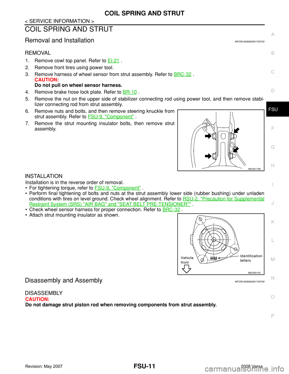
6. Remove nuts and bolts, and then remove steering knuckle from
strut assembly. Refer to FSU-9, "
Component" .
7. Remove the strut mounting insulator bolts, then remove strut
assembly.
INSTALLATION
Installation is in the reverse order of removal.
• For tightening torque, refer to FSU-9, "
Component" .
• Perform final tightening of bolts and nuts at the strut assembly lower side (rubber bushing) under unladen
conditions with tires on level ground. Check wheel alignment. Refer to RSU-2, "
Precaution for Supplemental
Restraint System (SRS) "AIR BAG" and "SEAT BELT PRE-TENSIONER"" .
• Check wheel sensor harness for proper connection. Refer to BRC-32
.
• Attach strut mounting insulator as shown.
Disassembly and AssemblyINFOID:0000000001703726
DISASSEMBLY
CAUTION:
Do not damage strut piston rod when removing components from strut assembly.
WEIA0179E
MEIA0014E
Page 1912 of 2771
WINDSHIELD GLASS
GW-11
< SERVICE INFORMATION >
C
D
E
F
G
H
J
K
L
MA
B
GW
N
O
P
WINDSHIELD GLASS
Removal and InstallationINFOID:0000000001704135
REMOVAL
1. Partially remove the headlining (front edge). Refer to EI-45.
2. Remove the front wiper arms. Refer to WW-18, "
Removal and Installation of Front Wiper Arms".
3. Remove the cowl top cover. Refer to EI-21
.
4. Disconnect the harness connector of wiper deicer.
5. Apply protective tape around the windshield glass to protect the painted surface from damage.
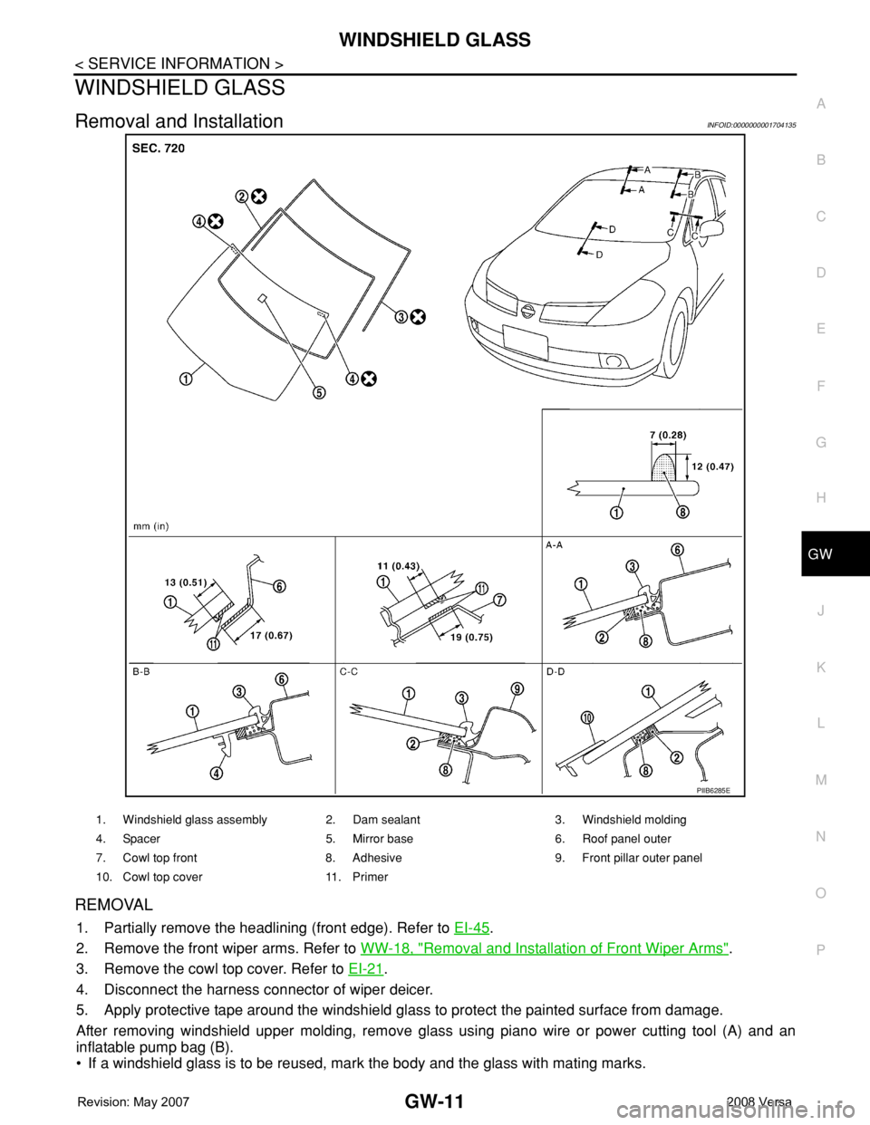
After removing windshield upper molding, remove glass using piano wire or power cutting tool (A) and an
inflatable pump bag (B).
• If a windshield glass is to be reused, mark the body and the glass with mating marks.
PIIB6285E
1. Windshield glass assembly 2. Dam sealant 3. Windshield molding
4. Spacer 5. Mirror base 6. Roof panel outer
7. Cowl top front 8. Adhesive 9. Front pillar outer panel
10. Cowl top cover 11. Primer