Page 300 of 2771
AT-288
< SERVICE INFORMATION >
REPAIR FOR COMPONENT PARTS
5. Install snap ring using a flat-bladed screwdriver.
6. Set dial indicator A on retaining plate (1), and measure clear-
ance between retaining plate (1) and snap ring (2). If not within
allowable limit, select proper retaining plate (1). Refer to “Parts
Information” for retaining plate selection.
7. Check operation of high clutch. Refer to "DISASSEMBLY".
8. Install seal rings to input shaft assembly (high clutch drum).
CAUTION:
Roll paper around seal rings to prevent seal rings from spread-
ing.
Forward and Overrun ClutchesINFOID:0000000001703385
COMPONENTS
SCIA4891E
Specified clearance
Standard and allowable limit:
Refer to AT-343, "
Clutches and Brakes".
SCIA5858E
SCIA4890E
SAT198D
Page 301 of 2771

REPAIR FOR COMPONENT PARTS
AT-289
< SERVICE INFORMATION >
D
E
F
G
H
I
J
K
L
MA
B
AT
N
O
P
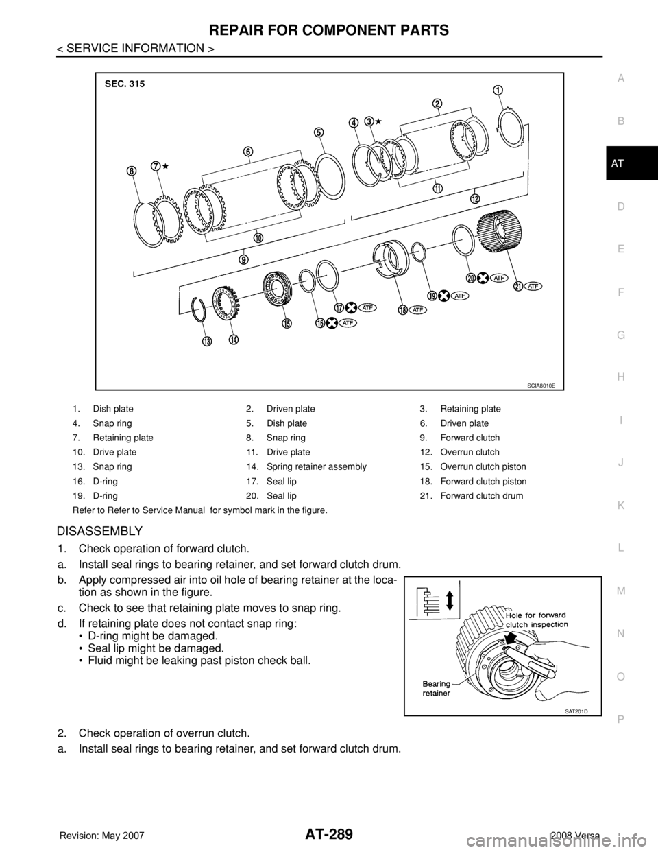
DISASSEMBLY
1. Check operation of forward clutch.
a. Install seal rings to bearing retainer, and set forward clutch drum.
b. Apply compressed air into oil hole of bearing retainer at the loca-
tion as shown in the figure.
c. Check to see that retaining plate moves to snap ring.
d. If retaining plate does not contact snap ring:
• D-ring might be damaged.
• Seal lip might be damaged.
• Fluid might be leaking past piston check ball.
2. Check operation of overrun clutch.
a. Install seal rings to bearing retainer, and set forward clutch drum.
1. Dish plate 2. Driven plate 3. Retaining plate
4. Snap ring 5. Dish plate 6. Driven plate
7. Retaining plate 8. Snap ring 9. Forward clutch
10. Drive plate 11. Drive plate 12. Overrun clutch
13. Snap ring 14. Spring retainer assembly 15. Overrun clutch piston
16. D-ring 17. Seal lip 18. Forward clutch piston
19. D-ring 20. Seal lip 21. Forward clutch drum
Refer to Refer to Service Manual for symbol mark in the figure.
SCIA8010E
SAT201D
Page 307 of 2771

REPAIR FOR COMPONENT PARTS
AT-295
< SERVICE INFORMATION >
D
E
F
G
H
I
J
K
L
MA
B
AT
N
O
P
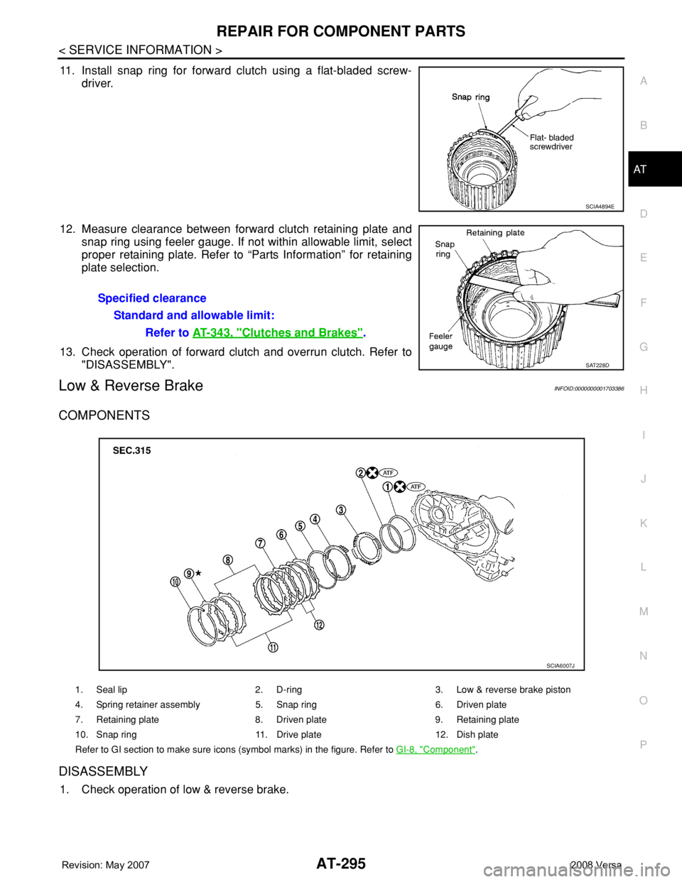
11. Install snap ring for forward clutch using a flat-bladed screw-
driver.
12. Measure clearance between forward clutch retaining plate and
snap ring using feeler gauge. If not within allowable limit, select
proper retaining plate. Refer to “Parts Information” for retaining
plate selection.
13. Check operation of forward clutch and overrun clutch. Refer to
"DISASSEMBLY".
Low & Reverse BrakeINFOID:0000000001703386
COMPONENTS
DISASSEMBLY
1. Check operation of low & reverse brake.
SCIA4894E
Specified clearance
Standard and allowable limit:
Refer to AT-343, "
Clutches and Brakes".
SAT228D
1. Seal lip 2. D-ring 3. Low & reverse brake piston
4. Spring retainer assembly 5. Snap ring 6. Driven plate
7. Retaining plate 8. Driven plate 9. Retaining plate
10. Snap ring 11. Drive plate 12. Dish plate
Refer to GI section to make sure icons (symbol marks) in the figure. Refer to GI-8, "
Component".
SCIA6007J
Page 312 of 2771
AT-300
< SERVICE INFORMATION >
REPAIR FOR COMPONENT PARTS
DISASSEMBLY
1. Remove forward clutch hub from rear internal gear.
2. Remove end bearing (1) from rear internal gear (2).
3. Remove thrust washer from rear internal gear.
4. Remove end bearing (2) from forward one-way clutch (3).
(1): Forward clutch hub
1. End bearing 2. Forward clutch hub 3. Thrust washer
4. Rear internal gear 5. Forward one-way clutch
Refer to GI section to make sure icons (symbol marks) in the figure. Refer to GI-8, "
Component".
SAT251D
SCIA7028E
SCIA3691E
SCIA7026E
Page 315 of 2771
REPAIR FOR COMPONENT PARTS
AT-303
< SERVICE INFORMATION >
D
E
F
G
H
I
J
K
L
MA
B
AT
N
O
P
DISASSEMBLY
1. Remove seal rings (1) from output shaft (2) and bearing retainer
(3).
1. Lock nut 2. Idler gear 3. Idler gear bearing
4. Reduction pinion gear adjusting
shim5. Reduction pinion gear bearing 6. Reduction pinion gear
7. Seal ring 8. Snap ring 9. Radial needle bearing
10. Bearing retainer 11. Thrust needle bearing 12. Seal ring
13. Output shaft 14. Output shaft bearing 15. Output shaft adjusting shim
Refer to GI section to make sure icons (symbol marks) in the figure. Refer to GI-8, "
Component".
SCIA7944E
SCIA7992E
Page 320 of 2771

AT-308
< SERVICE INFORMATION >
REPAIR FOR COMPONENT PARTS
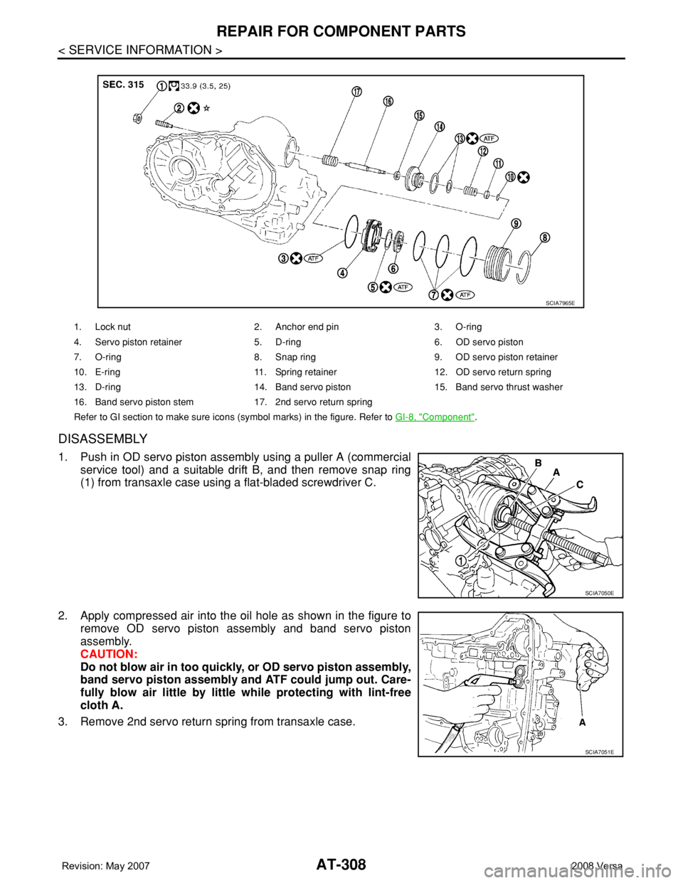
DISASSEMBLY
1. Push in OD servo piston assembly using a puller A (commercial
service tool) and a suitable drift B, and then remove snap ring
(1) from transaxle case using a flat-bladed screwdriver C.
2. Apply compressed air into the oil hole as shown in the figure to
remove OD servo piston assembly and band servo piston
assembly.
CAUTION:
Do not blow air in too quickly, or OD servo piston assembly,
band servo piston assembly and ATF could jump out. Care-
fully blow air little by little while protecting with lint-free
cloth A.
3. Remove 2nd servo return spring from transaxle case.
1. Lock nut 2. Anchor end pin 3. O-ring
4. Servo piston retainer 5. D-ring 6. OD servo piston
7. O-ring 8. Snap ring 9. OD servo piston retainer
10. E-ring 11. Spring retainer12. OD servo return spring
13. D-ring 14. Band servo piston 15. Band servo thrust washer
16. Band servo piston stem 17. 2nd servo return spring
Refer to GI section to make sure icons (symbol marks) in the figure. Refer to GI-8, "
Component".
SCIA7965E
SCIA7050E
SCIA7051E
Page 325 of 2771
REPAIR FOR COMPONENT PARTS
AT-313
< SERVICE INFORMATION >
D
E
F
G
H
I
J
K
L
MA
B
AT
N
O
P
11. Push in OD servo piston assembly using a puller A (commercial
service tool) and a suitable drift B, and install snap ring (1) to
transaxle case using a flat-bladed screwdriver C.
Final DriveINFOID:0000000001703390
COMPONENTS
DISASSEMBLY
1. Remove final gear (1) from differential case (2).
SCIA7050E
1. Pinion mate gear 2. Pinion mate gear thrust washer 3. Pinion mate shaft
4. Lock pin 5. Side gear 6. Side gear thrust washer
7. Differential side bearing 8. Speedometer drive gear 9. Differential case
10. Final gear 11. Differential side bearing 12. Differential side bearing adjusting
shim
Refer to GI section to make sure icons (symbol marks) in the figure. Refer to GI-8, "
Component".
SCIA7962E
SCIA8003E
Page 732 of 2771

BR-1
BRAKES
C
D
E
G
H
I
J
K
L
M
SECTION BR
A
B
BR
N
O
P
CONTENTS
BRAKE SYSTEM
SERVICE INFORMATION ............................2
PRECAUTIONS ...................................................2
Precaution for Supplemental Restraint System
(SRS) "AIR BAG" and "SEAT BELT PRE-TEN-
SIONER" ...................................................................
2
Precaution for Brake System ....................................2
PREPARATION ...................................................3
Commercial Service Tool ..........................................3
NOISE, VIBRATION AND HARSHNESS
(NVH) TROUBLESHOOTING .............................
4
NVH Troubleshooting Chart ......................................4
BRAKE PEDAL ...................................................5
Inspection and Adjustment ........................................5
Removal and Installation ...........................................6
BRAKE FLUID .....................................................8
On Board Inspection .................................................8
Drain and Refill ..........................................................8
Bleeding Brake System .............................................8
BRAKE TUBE AND HOSE ................................10
Hydraulic Circuit ......................................................10
Front Brake Tube and Hose ....................................10
Rear Brake Tube and Hose ....................................11
Inspection After Installation .....................................11
BRAKE MASTER CYLINDER ............................13
On-Board Inspection ...............................................13
Removal and Installation .........................................13
Disassembly and Assembly ....................................13
BRAKE BOOSTER ...........................................18
On Board Inspection ................................................18
Removal and Installation .........................................18
VACUUM LINES ...............................................21
Component ..............................................................21
Removal and Installation .........................................21
Inspection ................................................................21
FRONT DISC BRAKE .......................................23
On Board Inspection ................................................23
Component ..............................................................23
Removal and Installation of Brake Pad ...................24
Removal and Installation of Brake Caliper Assem-
bly ............................................................................
25
Disassembly and Assembly of Brake Caliper As-
sembly .....................................................................
25
Brake Burnishing Procedure ....................................28
REAR DRUM BRAKE .......................................29
Component ..............................................................29
Removal and Installation of Drum Brake Assembly
....
29
Removal and Installation of Wheel Cylinder ............32
Disassembly and Assembly of Wheel Cylinder .......32
SERVICE DATA AND SPECIFICATIONS
(SDS) .................................................................
33
General Specification ..............................................33
Brake Pedal .............................................................33
Check Valve ............................................................33
Brake Booster ..........................................................33
Front Disc Brake ......................................................33
Rear Drum Brake .....................................................34