Page 2633 of 2771

REAR SEAT
SE-25
< SERVICE INFORMATION >
C
D
E
F
G
H
J
K
L
MA
B
SE
N
O
P Disassembly of Seat Cushion Trim and Pad
Remove the rings to separate the trim and pad.
Assembly of Seat Cushion Trim and Pad
Assembly is the reverse order of disassembly.
Removal and InstallationINFOID:0000000001704272
CAUTION:
When removing and installing, use shop cloths to protect parts from damage.
FIXED BACK SEAT
Removal
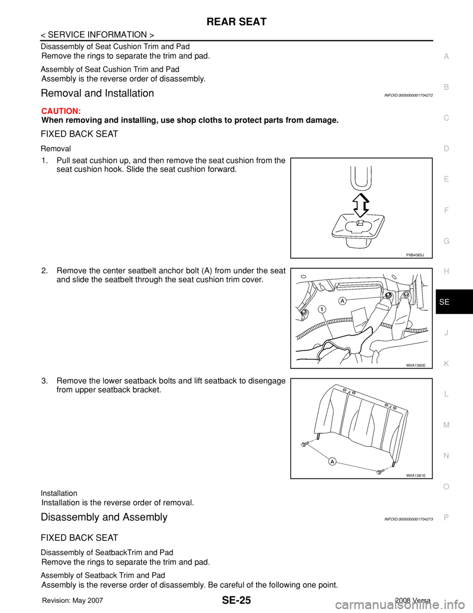
1. Pull seat cushion up, and then remove the seat cushion from the
seat cushion hook. Slide the seat cushion forward.
2. Remove the center seatbelt anchor bolt (A) from under the seat
and slide the seatbelt through the seat cushion trim cover.
3. Remove the lower seatback bolts and lift seatback to disengage
from upper seatback bracket.
Installation
Installation is the reverse order of removal.
Disassembly and AssemblyINFOID:0000000001704273
FIXED BACK SEAT
Disassembly of SeatbackTrim and Pad
Remove the rings to separate the trim and pad.
Assembly of Seatback Trim and Pad
Assembly is the reverse order of disassembly. Be careful of the following one point.
PIIB4085J
WIIA1380E
WIIA1381E
Page 2634 of 2771
SE-26
< SERVICE INFORMATION >
REAR SEAT
Disassembly of Seat Cushion Trim and Pad
Remove the rings to separate the trim and pad.
Assembly of Seat Cushion Trim and Pad
Assembly is the reverse order of disassembly.
Page 2679 of 2771
OCCUPANT CLASSIFICATION SYSTEM CONTROL UNIT
SRS-45
< ON-VEHICLE REPAIR >
C
D
E
F
G
I
J
K
L
MA
B
SRS
N
O
P
OCCUPANT CLASSIFICATION SYSTEM CONTROL UNIT
Removal and InstallationINFOID:0000000001703935
The occupant classification system control unit, occupant classification system sensor, and bladder are an
integral part of the front passenger seat cushion and are replaced as an assembly. Refer to SE-10
to remove
the seat, and SE-12, "
Disassembly and Assembly" to replace the seat cushion.
Page 2731 of 2771

REMOVAL AND INSTALLATION
WT-23
< SERVICE INFORMATION >
C
D
F
G
H
I
J
K
L
MA
B
WT
N
O
P
REMOVAL AND INSTALLATION
Transmitter (Pressure Sensor)INFOID:0000000001703772
REMOVAL
1. Remove wheel and tire using power tool.
2. Deflate tire. Unscrew transmitter retaining nut and allow transmitter to fall into tire.
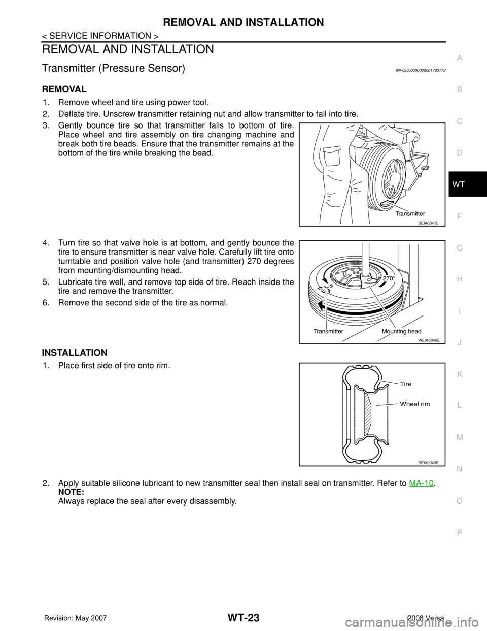
3. Gently bounce tire so that transmitter falls to bottom of tire.
Place wheel and tire assembly on tire changing machine and
break both tire beads. Ensure that the transmitter remains at the
bottom of the tire while breaking the bead.
4. Turn tire so that valve hole is at bottom, and gently bounce the
tire to ensure transmitter is near valve hole. Carefully lift tire onto
turntable and position valve hole (and transmitter) 270 degrees
from mounting/dismounting head.
5. Lubricate tire well, and remove top side of tire. Reach inside the
tire and remove the transmitter.
6. Remove the second side of the tire as normal.
INSTALLATION
1. Place first side of tire onto rim.
2. Apply suitable silicone lubricant to new transmitter seal then install seal on transmitter. Refer to MA-10
.
NOTE:
Always replace the seal after every disassembly.
SEIA0047E
WEIA0046E
SEIA0049E