2008 NISSAN TIIDA disassembly
[x] Cancel search: disassemblyPage 2335 of 2771
FINAL DRIVE
MT-47
< SERVICE INFORMATION >
D
E
F
G
H
I
J
K
L
MA
B
MT
N
O
P
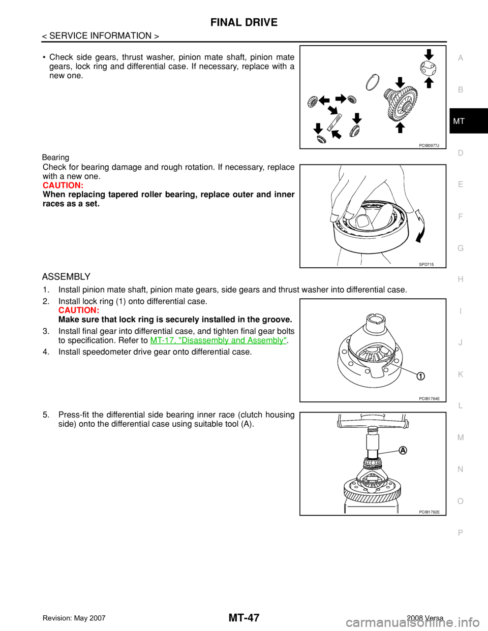
• Check side gears, thrust washer, pinion mate shaft, pinion mate
gears, lock ring and differential case. If necessary, replace with a
new one.
Bearing
Check for bearing damage and rough rotation. If necessary, replace
with a new one.
CAUTION:
When replacing tapered roller bearing, replace outer and inner
races as a set.
ASSEMBLY
1. Install pinion mate shaft, pinion mate gears, side gears and thrust washer into differential case.
2. Install lock ring (1) onto differential case.
CAUTION:
Make sure that lock ring is securely installed in the groove.
3. Install final gear into differential case, and tighten final gear bolts
to specification. Refer to MT-17, "
Disassembly and Assembly".
4. Install speedometer drive gear onto differential case.
5. Press-fit the differential side bearing inner race (clutch housing
side) onto the differential case using suitable tool (A).
PCIB0977J
SPD715
PCIB1764E
PCIB1762E
Page 2339 of 2771

MTC-1
AIR CONDITIONER
C
D
E
F
G
H
I
K
L
M
SECTION MTC
A
B
MTC
N
O
P
CONTENTS
MANUAL AIR CONDITIONER
SERVICE INFORMATION ............................3
PRECAUTIONS ...................................................3
Precaution for Supplemental Restraint System
(SRS) "AIR BAG" and "SEAT BELT PRE-TEN-
SIONER" ...................................................................
3
Precaution for Procedure without Cowl Top Cover ......3
Precaution for Working with HFC-134a (R-134a) ......3
General Refrigerant Precaution ................................4
Oil Precaution ............................................................4
Precaution for Refrigerant Connection ......................4
Precaution for Service of Compressor ......................7
Precaution for Service Equipment .............................7
Precaution for Leak Detection Dye ...........................9
PREPARATION ..................................................10
Special Service Tool ...............................................10
HFC-134a (R-134a) Service Tool and Equipment ....10
Commercial Service Tool ........................................13
REFRIGERATION SYSTEM ..............................14
Refrigerant Cycle ....................................................14
Refrigerant System Protection ................................14
Component Part Location .......................................15
OIL ......................................................................16
Maintenance of Oil Quantity in Compressor ...........16
AIR CONDITIONER CONTROL .........................19
Control Operation ....................................................19
Discharge Air Flow ..................................................20
System Description .................................................20
CAN Communication System Description ...............21
TROUBLE DIAGNOSIS .....................................22
CONSULT-III Function (BCM) .................................22
How to Perform Trouble Diagnosis for Quick and
Accurate Repair ......................................................
22
Component Parts and Harness Connector Loca-
tion ..........................................................................
23
Schematic ...............................................................25
Wiring Diagram - Heater - .......................................26
Wiring Diagram - A/C,M - ........................................27
Operational Check ...................................................30
Mode Door ...............................................................31
Air Mix Door .............................................................32
Intake Door ..............................................................33
Front Blower Motor Circuit .......................................33
Magnet Clutch Circuit (If Equipped) .........................37
Insufficient Cooling ..................................................45
Insufficient Heating ..................................................52
Noise .......................................................................53
CONTROLLER ..................................................55
Removal and Installation .........................................55
Disassembly and Assembly .....................................56
THERMO CONTROL AMPLIFIER ....................57
Removal and Installation .........................................57
A/C UNIT ASSEMBLY ......................................58
Removal and Installation .........................................58
Disassembly and Assembly .....................................60
BLOWER MOTOR ............................................62
Removal and Installation .........................................62
INTAKE DOOR ..................................................63
Intake Door Cable Adjustment .................................63
AIR MIX DOOR .................................................64
Air Mix Door Cable Adjustment ...............................64
MODE DOOR ....................................................65
Mode Door Cable Adjustment .................................65
BLOWER FAN RESISTOR ...............................66
Removal and Installation .........................................66
HEATER CORE .................................................67
Removal and Installation .........................................67
AIR CONDITIONER FILTER .............................68
Removal and Installation .........................................68
Page 2393 of 2771
CONTROLLER
MTC-55
< SERVICE INFORMATION >
C
D
E
F
G
H
I
K
L
MA
B
MTC
N
O
P
CONTROLLER
Removal and InstallationINFOID:0000000001704309
REMOVAL
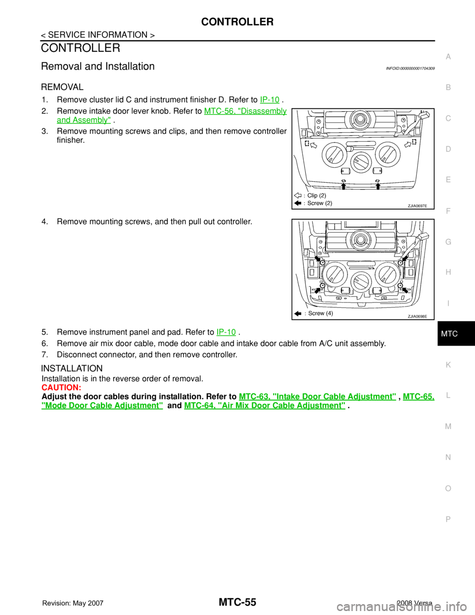
1. Remove cluster lid C and instrument finisher D. Refer to IP-10 .
2. Remove intake door lever knob. Refer to MTC-56, "
Disassembly
and Assembly" .
3. Remove mounting screws and clips, and then remove controller
finisher.
4. Remove mounting screws, and then pull out controller.
5. Remove instrument panel and pad. Refer to IP-10
.
6. Remove air mix door cable, mode door cable and intake door cable from A/C unit assembly.
7. Disconnect connector, and then remove controller.
INSTALLATION
Installation is in the reverse order of removal.
CAUTION:
Adjust the door cables during installation. Refer to MTC-63, "
Intake Door Cable Adjustment" , MTC-65,
"Mode Door Cable Adjustment" and MTC-64, "Air Mix Door Cable Adjustment" .
ZJIA0697E
ZJIA0698E
Page 2394 of 2771
MTC-56
< SERVICE INFORMATION >
CONTROLLER
Disassembly and Assembly
INFOID:0000000001704310
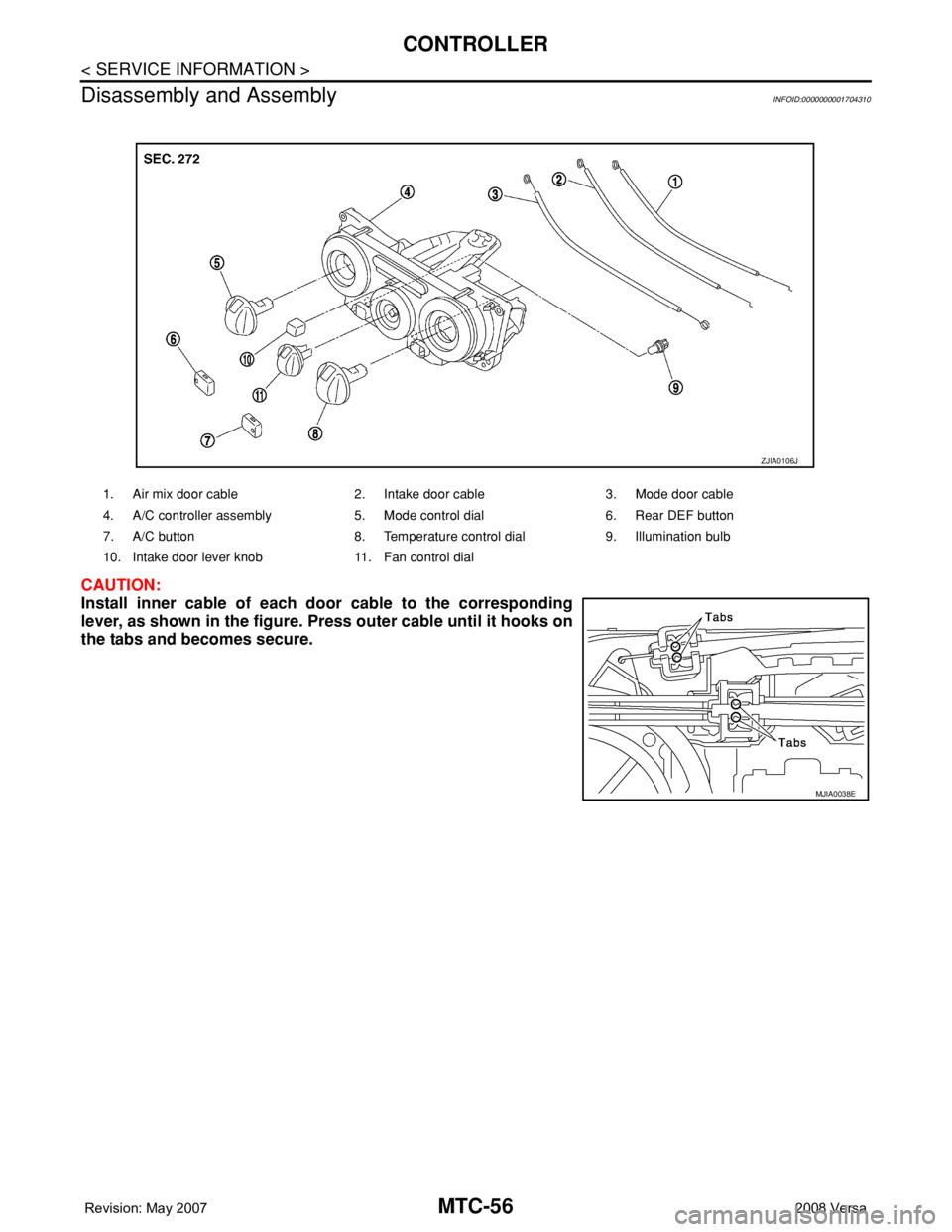
CAUTION:
Install inner cable of each door cable to the corresponding
lever, as shown in the figure. Press outer cable until it hooks on
the tabs and becomes secure.
1. Air mix door cable 2. Intake door cable 3. Mode door cable
4. A/C controller assembly 5. Mode control dial 6. Rear DEF button
7. A/C button 8. Temperature control dial 9. Illumination bulb
10. Intake door lever knob 11. Fan control dial
ZJIA0106J
MJIA0038E
Page 2398 of 2771
MTC-60
< SERVICE INFORMATION >
A/C UNIT ASSEMBLY
Disassembly and Assembly
INFOID:0000000001704313
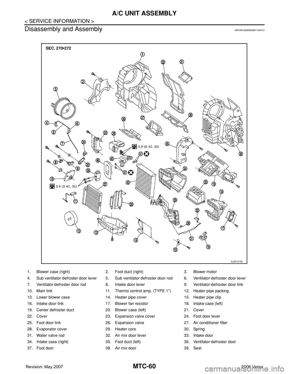
1. Blower case (right) 2. Foot duct (right) 3. Blower motor
4. Sub ventilator·defroster door lever 5. Sub ventilator·defroster door rod 6. Ventilator·defroster door lever
7. Ventilator·defroster door rod 8. Intake door lever 9. Ventilator·defroster door link
10. Main link 11. Thermo control amp. (TYPE 1*) 12. Heater pipe packing
13. Lower blower case 14. Heater pipe cover 15. Heater pipe clip
16. Intake door link 17. Blower fan resistor 18. Intake case (left)
19. Center defroster duct 20. Blower case (left) 21. Cover
22. Cover 23. Expansion valve cover 24. Foot door lever
25. Foot door link 26. Expansion valve 27. Air conditioner filter
28. Evaporator cover 29. Heater core 30. Spring
31. Water valve rod 32. Air mix door lever 33. Intake door
34. Intake case (right) 35. Foot duct (left) 36. Ventilator·defroster door
37. Foot door 38. Air mix door 39. Seal
SJIA1515E
Page 2507 of 2771

PS-1
STEERING
C
D
E
F
H
I
J
K
L
M
SECTION PS
A
B
PS
N
O
P
CONTENTS
POWER STEERING SYSTEM
SERVICE INFORMATION ............................2
PRECAUTIONS ...................................................2
Precaution for Supplemental Restraint System
(SRS) "AIR BAG" and "SEAT BELT PRE-TEN-
SIONER" ...................................................................
2
Precaution Necessary for Steering Wheel Rota-
tion After Battery Disconnect .....................................
2
Precaution for Steering System ................................2
PREPARATION ...................................................4
Special Service Tool .................................................4
Commercial Service Tool ..........................................4
NOISE, VIBRATION AND HARSHNESS
(NVH) TROUBLESHOOTING .............................
5
NVH Troubleshooting Chart ......................................5
STEERING WHEEL ...........................................6
On-Vehicle Inspection and Service ..........................6
Removal and Installation ..........................................7
STEERING COLUMN .........................................9
Removal and Installation ..........................................9
POWER STEERING GEAR ..............................12
Removal and Installation .........................................12
Disassembly and Assembly .....................................13
SERVICE DATA AND SPECIFICATIONS
(SDS) .................................................................
17
Steering Wheel ........................................................17
Steering Angle .........................................................17
Steering Column ......................................................17
Steering Outer Socket and Inner Socket .................17
Steering Gear ..........................................................18
Page 2509 of 2771

PRECAUTIONS
PS-3
< SERVICE INFORMATION >
C
D
E
F
H
I
J
K
L
MA
B
PS
N
O
P
- Before disassembly, thoroughly clean the outside of the unit.
- Disassembly should be done in a clean work area. It is important to prevent the internal parts from becoming
contaminated by dirt or other foreign matter.
- For easier and proper assembly, place disassembled parts in order on a parts rack.
- Use nylon cloth or paper towels to clean the parts; common shop rags can leave lint that might interfere with
their operation.
- Do not reuse non-reusable parts.
- Before assembling, apply the specified grease to the directed parts.
Page 2519 of 2771
POWER STEERING GEAR
PS-13
< SERVICE INFORMATION >
C
D
E
F
H
I
J
K
L
MA
B
PS
N
O
P
• Check wheel alignment under unladen conditions with tires on level ground. Refer to FSU-6, "Wheel Align-
ment Inspection".
INSPECTION AFTER INSTALLATION
Rotate steering wheel to check for decentered condition, binding, noise or excessive steering effort.
Disassembly and AssemblyINFOID:0000000001703863
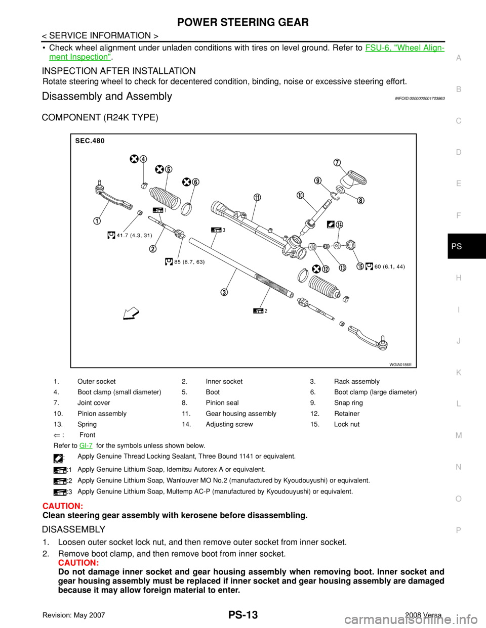
COMPONENT (R24K TYPE)
CAUTION:
Clean steering gear assembly with kerosene before disassembling.
DISASSEMBLY
1. Loosen outer socket lock nut, and then remove outer socket from inner socket.
2. Remove boot clamp, and then remove boot from inner socket.
CAUTION:
Do not damage inner socket and gear housing assembly when removing boot. Inner socket and
gear housing assembly must be replaced if inner socket and gear housing assembly are damaged
because it may allow foreign material to enter.
1. Outer socket 2. Inner socket 3. Rack assembly
4. Boot clamp (small diameter) 5. Boot 6. Boot clamp (large diameter)
7. Joint cover 8. Pinion seal 9. Snap ring
10. Pinion assembly 11. Gear housing assembly 12. Retainer
13. Spring 14. Adjusting screw 15. Lock nut
⇐ : Front
Refer to GI-7
for the symbols unless shown below.
:Apply Genuine Thread Locking Sealant, Three Bound 1141 or equivalent.
:1Apply Genuine Lithium Soap, Idemitsu Autorex A or equivalent.
:2Apply Genuine Lithium Soap, Wanlouver MO No.2 (manufactured by Kyoudouyushi) or equivalent.
:3Apply Genuine Lithium Soap, Multemp AC-P (manufactured by Kyoudouyushi) or equivalent.
WGIA0186E