Page 2520 of 2771

PS-14
< SERVICE INFORMATION >
POWER STEERING GEAR
3. Remove inner socket from rack assembly while holding the flat portion of the rack next to the inner socket
using a suitable tool.
4. Measure adjusting screw height “H”, and loosen lock nut (2).
5. Remove adjusting screw (1), retainer (3) and spring (4) from
gear housing assembly (5).
INSPECTION AFTER DISASSEMBLY
Joint Cover
Check joint cover protrusion for damage. Replace if there are.
Rack and Pinion Assembly
• Check pinion assembly for damage or wear. Replace as necessary.
• Rotate pinion assembly and check for torque variation or rattle. Replace steering gear as necessary.
Gear Housing Assembly
Check gear housing assembly for damage or scratches. Replace steering gear as necessary.
Outer Socket and Inner Socket
1. Check ball joint swinging torque.
• Hook a spring balance at the point shown and pull the spring
balance. Make sure that the spring balance reads the speci-
fied value when ball stud and inner socket start to move.
Replace outer socket and inner socket if they are outside the
standard.
2. Ball joint axial end play
SGIA1300E
SGIA0896E
Items Outer socket Inner socket
Measuring point of spring bal-
anceBall stud upper sideMeasuring point at * mark shown
in the figure
Swinging torque0.3 - 2.9 N·m
(0.03 - 0.29 kg-m, 3.0 - 25 in-lb)0.5 - 5.0 N·m
(0.06 - 0.51 kg-m, 5 - 44 in-lb)
Spring balance measurement6.0 - 58 N
(0.61 - 5.91 kg-f, 1.35 - 13.03 lb-f)4.3 - 43.5 N
(0.44 - 4.44 kg-f, 0.97 - 9.79 lb-f)
Page 2609 of 2771

SE-1
BODY
C
D
E
F
G
H
J
K
L
M
SECTION SE
A
B
SE
N
O
P
CONTENTS
SEAT
SERVICE INFORMATION ............................2
PRECAUTIONS ...................................................2
Precaution for Supplemental Restraint System
(SRS) "AIR BAG" and "SEAT BELT PRE-TEN-
SIONER" ...................................................................
2
Service Notice ...........................................................2
Precaution .................................................................2
PREPARATION ...................................................3
Special Service Tool .................................................3
Commercial Service Tool ..........................................3
SQUEAK AND RATTLE TROUBLE DIAG-
NOSES ................................................................
4
Work Flow .................................................................4
Generic Squeak and Rattle Troubleshooting ............6
Diagnostic Worksheet ...............................................8
FRONT SEAT ....................................................10
Driver Seat ...............................................................10
Passenger Seat .......................................................11
Removal and Installation .........................................11
Disassembly and Assembly .....................................12
REAR SEAT ......................................................14
Component Parts Drawing ......................................14
Removal and Installation .........................................15
Disassembly and Assembly .....................................17
Component Parts Drawing ......................................20
Removal and Installation .........................................21
Disassembly and Assembly .....................................23
Removal and Installation .........................................25
Disassembly and Assembly .....................................25
Page 2620 of 2771

SE-12
< SERVICE INFORMATION >
FRONT SEAT
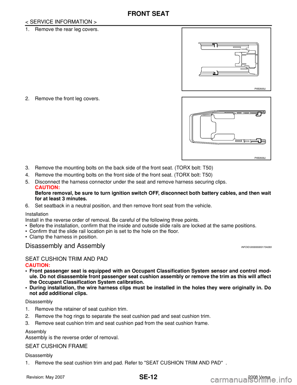
1. Remove the rear leg covers.
2. Remove the front leg covers.
3. Remove the mounting bolts on the back side of the front seat. (TORX bolt: T50)
4. Remove the mounting bolts on the front side of the front seat. (TORX bolt: T50)
5. Disconnect the harness connector under the seat and remove harness securing clips.
CAUTION:
Before removal, be sure to turn ignition switch OFF, disconnect both battery cables, and then wait
for at least 3 minutes.
6. Set seatback in a neutral position, and then remove front seat from the vehicle.
Installation
Install in the reverse order of removal. Be careful of the following three points.
• Before the installation, confirm that the inside and outside slide rails are locked at the same positions.
• Confirm that the slide rail location pin is set to the hole on the floor.
• Clamp the harness in position.
Disassembly and AssemblyINFOID:0000000001704265
SEAT CUSHION TRIM AND PAD
CAUTION:
• Front passenger seat is equipped with an Occupant Classification System sensor and control mod-
ule. Do not disassemble front passenger seat cushion assembly or remove the trim as this will affect
the Occupant Classification System calibration.
• During installation, the wire harness clips must be installed in the holes they were originally in. Do
not add additional clips.
Disassembly
1. Remove the retainer of seat cushion trim.
2. Remove the hog rings to separate the seat cushion pad and seat cushion trim.
3. Remove seat cushion trim and seat cushion pad from the seat cushion frame.
Assembly
Assembly is the reverse order of removal.
SEAT CUSHION FRAME
Disassembly
1. Remove the seat cushion trim and pad. Refer to "SEAT CUSHION TRIM AND PAD" .
PIIB2669J
PIIB2668J
Page 2625 of 2771
REAR SEAT
SE-17
< SERVICE INFORMATION >
C
D
E
F
G
H
J
K
L
MA
B
SE
N
O
P
1. Install the rear seatback side bracket in the vehicle.
2. Temporarily tighten the seatback assembly and rear seatback side bracket.
3. Lift to fold up seatback assembly. Be sure to lock seatback assembly to rear seat striker.
4. Tighten the bolt.
NOTE:
Confirm that side hinge bracket location pin is set to the hole on the seatback backside.
Disassembly and AssemblyINFOID:0000000001704268
60:40 SPLIT FOLD DOWN SEAT - HATCHBACK
Disassembly of Armrest
1. Fold up the backside of the seatback trim and then remove the
armrest nuts.
2. Push the armrest toward left side while pulling backward to
remove.
3. Remove the rear seat bushing, and then remove the armrest
hinge cover by pulling it backward.
PIIB2484J
PIIB2913J
PIIB2915J
PIIB6507E
Page 2626 of 2771
SE-18
< SERVICE INFORMATION >
REAR SEAT
Assembly of Armrest
Assembly in the reverse order of disassembly.
Disassembly of Seatback Trim and Pad
1. Remove the headrest.
2. Remove the retainer under the back of seatback.
3. Remove the clips, and then remove the striker cover.
4. Remove the headrest holder.
5. To remove armrest, refer to "Disassembly of Armrest " .
6. Remove the seatback trim.
7. Remove the bolts, and then remove the rear seat lock assembly.
8. Remove the seatback pad from the seatback frame.
9. Remove the seatback center bracket bolt and then remove the seatback frame.
PIIB2486J
PIIB2485J
PIIB4084J
PIIB2487J
Page 2627 of 2771
REAR SEAT
SE-19
< SERVICE INFORMATION >
C
D
E
F
G
H
J
K
L
MA
B
SE
N
O
P Assembly of Seatback Trim and Pad
Assembly is the reverse order of disassembly. Be careful of the following one point.
• Before installing headrest holder, check its orientation (front/rear and right/left).
Disassembly of Seat Cushion Trim and Pad
Remove the rings to separate the trim and pad.
Assembly of Seat Cushion Trim and Pad
Assembly is the reverse order of disassembly.
Page 2631 of 2771
REAR SEAT
SE-23
< SERVICE INFORMATION >
C
D
E
F
G
H
J
K
L
MA
B
SE
N
O
P
NOTE:
Confirm that side hinge bracket location pin is set to the hole on the seatback backside.
Disassembly and AssemblyINFOID:0000000001704271
60:40 SPLIT FOLD DOWN SEAT - SEDAN
Disassembly of Armrest
1. Fold down the armrest and remove the armrest bolt cover (A).
2. Remove the armrest bolt (A).
3. Push the armrest toward left side while pulling backward to
remove.
4. Remove the rear seat bushing, and then remove the armrest
hinge cover by pulling it backward.
Assembly of Armrest
Assembly in the reverse order of disassembly.
WIIA1384E
WIIA1385E
PIIB2915J
PIIB6507E
Page 2632 of 2771
SE-24
< SERVICE INFORMATION >
REAR SEAT
Disassembly of Seatback Trim and Pad
1. Remove the headrest.
2. Remove the retainer under the back of seatback.
3. Remove the clips, and then remove the striker cover.
4. Remove the headrest holder.
5. To remove armrest, refer to "Disassembly of Armrest " .
6. Remove the seatback trim.
7. Remove the bolts, and then remove the rear seat lock assembly.
8. Remove the seatback pad from the seatback frame.
9. Remove the seatback center bracket bolt and then remove the seatback frame.
Assembly of Seatback Trim and Pad
Assembly is the reverse order of disassembly. Be careful of the following one point.
• Before installing headrest holder, check its orientation (front/rear and right/left).
PIIB2486J
PIIB2485J
PIIB4084J
PIIB2487J