Page 1945 of 2771

GW-44
< SERVICE INFORMATION >
FRONT DOOR GLASS AND REGULATOR
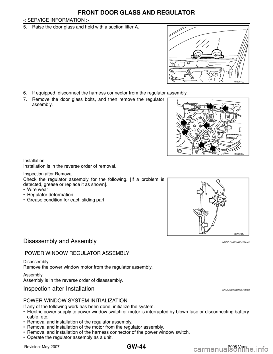
5. Raise the door glass and hold with a suction lifter A.
6. If equipped, disconnect the harness connector from the regulator assembly.
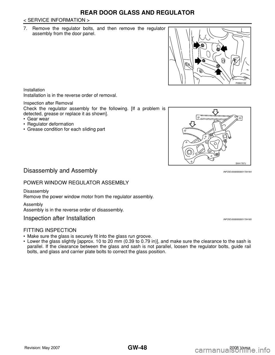
7. Remove the door glass bolts, and then remove the regulator
assembly.
Installation
Installation is in the reverse order of removal.
Inspection after Removal
Check the regulator assembly for the following. [If a problem is
detected, grease or replace it as shown].
• Wire wear
• Regulator deformation
• Grease condition for each sliding part
Disassembly and AssemblyINFOID:0000000001704161
POWER WINDOW REGULATOR ASSEMBLY
Disassembly
Remove the power window motor from the regulator assembly.
Assembly
Assembly is in the reverse order of disassembly.
Inspection after InstallationINFOID:0000000001704162
POWER WINDOW SYSTEM INITIALIZATION
If any of the following work has been done, initialize the system.
• Electric power supply to power window switch or motor is interrupted by blown fuse or disconnecting battery
cable, etc.
• Removal and installation of the regulator assembly.
• Removal and installation of the motor from the regulator assembly.
• Removal and installation of the harness connector of the power window switch.
• Operate the regulator assembly as a unit.
PIIB3510J
PIIB2633J
SIIA1781J
Page 1949 of 2771

GW-48
< SERVICE INFORMATION >
REAR DOOR GLASS AND REGULATOR
7. Remove the regulator bolts, and then remove the regulator
assembly from the door panel.
Installation
Installation is in the reverse order of removal.
Inspection after Removal
Check the regulator assembly for the following. [If a problem is
detected, grease or replace it as shown].
• Gear wear
• Regulator deformation
• Grease condition for each sliding part
Disassembly and AssemblyINFOID:0000000001704164
POWER WINDOW REGULATOR ASSEMBLY
Disassembly
Remove the power window motor from the regulator assembly.
Assembly
Assembly is in the reverse order of disassembly.
Inspection after InstallationINFOID:0000000001704165
FITTING INSPECTION
• Make sure the glass is securely fit into the glass run groove.
• Lower the glass slightly [approx. 10 to 20 mm (0.39 to 0.79 in)], and make sure the clearance to the sash is
parallel. If the clearance between the glass and sash is not parallel, loosen the regulator bolts, guide rail
bolts, and glass and carrier plate bolts to correct the glass position.
PIIB6315E
SIIA1787J
Page 1964 of 2771
DOOR MIRROR
GW-63
< SERVICE INFORMATION >
C
D
E
F
G
H
J
K
L
MA
B
GW
N
O
P
Removal and InstallationINFOID:0000000001704182
CAUTION:
Be careful not to damage the mirror body.
REMOVAL
1. Remove the front door finisher. Refer to EI-32, "Removal and Installation".
2. Disconnect the harness connector of door mirror.
3. Using a suitable tool remove door mirror base cover.
CAUTION:
• Do not reuse the disassembled door mirror base cover.
• Be careful not to damage the door panel with a tool.
4. Remove the door mirror bolts, and remove the door mirror
assembly.
CAUTION:
Do not use force to remove the door mirror assembly by
force because it is attached by clip.
INSTALLATION
Installation is in the reverse order of removal.
Disassembly and AssemblyINFOID:0000000001704183
DISASSEMBLY
1. Pull out all the terminals from the connector.
NOTE:
PIIB2638J
1. Door mirror base cover 2. Door mirror
PIIB2679E
PIIB6288E
Page 1967 of 2771

IP-1
BODY
C
D
E
F
G
H
J
K
L
M
SECTION IP
A
B
IP
N
O
P
CONTENTS
INSTRUMENT PANEL
PRECAUTION ...............................................2
PRECAUTIONS ...................................................2
Precaution for Supplemental Restraint System
(SRS) "AIR BAG" and "SEAT BELT PRE-TEN-
SIONER" ...................................................................
2
Precaution .................................................................2
PREPARATION ............................................3
PREPARATION ...................................................3
Special Service Tool .................................................3
Commercial Service Tool ..........................................3
SYMPTOM DIAGNOSIS ...............................4
SQUEAK AND RATTLE TROUBLE DIAG-
NOSES ...............................................................
4
Work Flow .................................................................4
Generic Squeak and Rattle Troubleshooting ............6
Diagnostic Worksheet ...............................................8
ON-VEHICLE REPAIR .................................10
INSTRUMENT PANEL ASSEMBLY .................10
Component Parts .....................................................10
Removal and Installation .........................................11
Disassembly and Assembly .....................................23
Page 1981 of 2771

INSTRUMENT PANEL ASSEMBLY
IP-15
< ON-VEHICLE REPAIR >
C
D
E
F
G
H
J
K
L
MA
B
IP
N
O
P
13. Remove instrument lower finisher.
a. Disengage pawls and remove fuse block lid.
b. Remove the screws.
c. Pull backward while disengaging the instrument lower finisher
clip and pawls.
d. Disconnect in-vehicle sensor and harness connector, and then
remove instrument lower finisher.
14. Remove glove box. Refer toIP-23, "
Disassembly and Assembly".
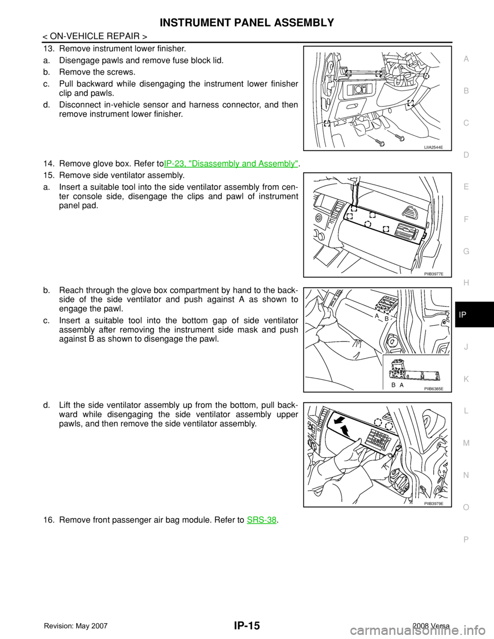
15. Remove side ventilator assembly.
a. Insert a suitable tool into the side ventilator assembly from cen-
ter console side, disengage the clips and pawl of instrument
panel pad.
b. Reach through the glove box compartment by hand to the back-
side of the side ventilator and push against A as shown to
engage the pawl.
c. Insert a suitable tool into the bottom gap of side ventilator
assembly after removing the instrument side mask and push
against B as shown to disengage the pawl.
d. Lift the side ventilator assembly up from the bottom, pull back-
ward while disengaging the side ventilator assembly upper
pawls, and then remove the side ventilator assembly.
16. Remove front passenger air bag module. Refer to SRS-38
.
LIIA2544E
PIIB3977E
PIIB6385E
PIIB3979E
Page 1989 of 2771
INSTRUMENT PANEL ASSEMBLY
IP-23
< ON-VEHICLE REPAIR >
C
D
E
F
G
H
J
K
L
MA
B
IP
N
O
P
12. Disengage console mask cover metal clips and pawls, and then
remove console mask cover (with armrest).
13. Disengage rear cup holder metal clips and pawls (without arm-
rest).
14. Remover rear cup holder (without armrest).
15. Remove console body assembly screws and nut.
16. Disconnect harness connector, and then remove console body assembly.
17. Remove both of the instrument lower cover LH and RH clips.
18. Disengage instrument lower cover LH and RH metal clips and
remove both of the instrument lower cover LH and RH.
19. Remove screws and then remove center console.
Installation
Installation is in the reverse order of removal.
Disassembly and AssemblyINFOID:0000000001704253
GLOVE BOX ASSEMBLY
PIIB6387E
PIIB6388E
PIIB2882J
Page 1990 of 2771
IP-24
< ON-VEHICLE REPAIR >
INSTRUMENT PANEL ASSEMBLY
Disassembly
1. Remove screws of damper, and then remove damper.
2. Remove screws of glove box striker, and then remove glove box striker.
3. Remove screws of glove box latch, and then remove glove box latch.
Assembly
Assembly is in the reverse order of disassembly.
CENTER CONSOLE ASSEMBLY
1. Glove box striker 2. Glove box 3. Glove box latch
4. Damper
LIIA2555E
Page 1991 of 2771
INSTRUMENT PANEL ASSEMBLY
IP-25
< ON-VEHICLE REPAIR >
C
D
E
F
G
H
J
K
L
MA
B
IP
N
O
P Disassembly
Remove the four screws, and then remove front cup holder from center console.
Assembly
Assembly is in the reverse order of disassembly.
COMBINATION METER
Disassembly
Disengage the eight tabs to separate front cover (1) from the unified
meter control unit assembly (2).
Assembly
Assembly is in the reverse order of disassembly.
1. Center console 2. Front cup holder
LIIA2556E
LIIA2582E