2008 NISSAN TIIDA disassembly
[x] Cancel search: disassemblyPage 1815 of 2771
FRONT DRIVE SHAFT
FAX-19
< SERVICE INFORMATION >
C
E
F
G
H
I
J
K
L
MA
B
FA X
N
O
P
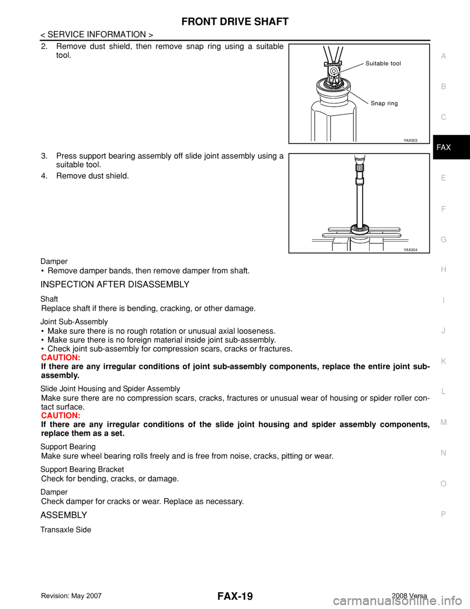
2. Remove dust shield, then remove snap ring using a suitable
tool.
3. Press support bearing assembly off slide joint assembly using a
suitable tool.
4. Remove dust shield.
Damper
• Remove damper bands, then remove damper from shaft.
INSPECTION AFTER DISASSEMBLY
Shaft
Replace shaft if there is bending, cracking, or other damage.
Joint Sub-Assembly
• Make sure there is no rough rotation or unusual axial looseness.
• Make sure there is no foreign material inside joint sub-assembly.
• Check joint sub-assembly for compression scars, cracks or fractures.
CAUTION:
If there are any irregular conditions of joint sub-assembly components, replace the entire joint sub-
assembly.
Slide Joint Housing and Spider Assembly
Make sure there are no compression scars, cracks, fractures or unusual wear of housing or spider roller con-
tact surface.
CAUTION:
If there are any irregular conditions of the slide joint housing and spider assembly components,
replace them as a set.
Support Bearing
Make sure wheel bearing rolls freely and is free from noise, cracks, pitting or wear.
Support Bearing Bracket
Check for bending, cracks, or damage.
Damper
Check damper for cracks or wear. Replace as necessary.
ASSEMBLY
Transaxle Side
YA X 0 0 3
YA X 0 0 4
Page 1835 of 2771
FSU-1
SUSPENSION
C
D
F
G
H
I
J
K
L
M
SECTION FSU
A
B
FSU
N
O
PCONTENTS
FRONT SUSPENSION
SERVICE INFORMATION ............................2
PRECAUTIONS ...................................................2
Precaution for Supplemental Restraint System
(SRS) "AIR BAG" and "SEAT BELT PRE-TEN-
SIONER" ...................................................................
2
Precaution for Procedure without Cowl Top Cover ......2
Cautions ....................................................................2
PREPARATION ...................................................3
Special Service Tool .................................................3
Commercial Service Tool ..........................................4
NOISE, VIBRATION AND HARSHNESS
(NVH) TROUBLESHOOTING .............................
5
NVH Troubleshooting Chart ......................................5
FRONT SUSPENSION ASSEMBLY ...................6
On-Vehicle Inspection and Service ...........................6
Wheel Alignment Inspection .....................................6
Component ...............................................................9
Removal and Installation .........................................10
COIL SPRING AND STRUT ..............................11
Removal and Installation .........................................11
Disassembly and Assembly .....................................11
TRANSVERSE LINK .........................................14
Removal and Installation .........................................14
STABILIZER BAR .............................................15
Removal and Installation .........................................15
SERVICE DATA AND SPECIFICATIONS
(SDS) .................................................................
16
Wheel Alignment (Unladen*) ...................................16
Ball Joint ..................................................................16
Wheelarch Height (Unladen*) ..................................17
Page 1845 of 2771
COIL SPRING AND STRUT
FSU-11
< SERVICE INFORMATION >
C
D
F
G
H
I
J
K
L
MA
B
FSU
N
O
P
COIL SPRING AND STRUT
Removal and InstallationINFOID:0000000001703725
REMOVAL
1. Remove cowl top panel. Refer to EI-21 .
2. Remove front tires using power tool.
3. Remove harness of wheel sensor from strut assembly. Refer to BRC-32
.
CAUTION:
Do not pull on wheel sensor harness.
4. Remove brake hose lock plate. Refer to BR-10
.
5. Remove the nut on the upper side of stabilizer connecting rod using power tool, and then remove stabi-
lizer connecting rod from strut assembly.
6. Remove nuts and bolts, and then remove steering knuckle from
strut assembly. Refer to FSU-9, "
Component" .
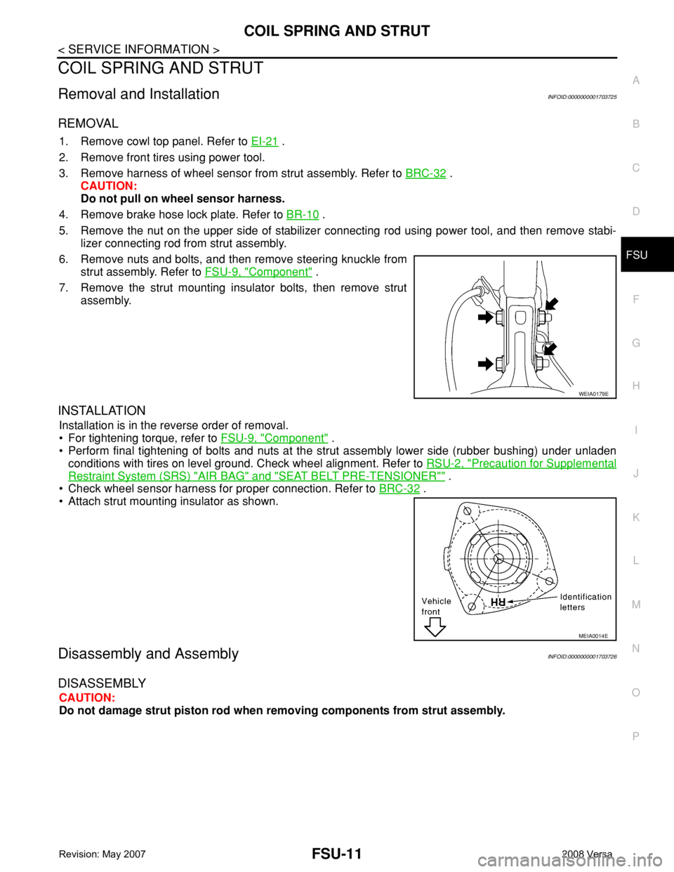
7. Remove the strut mounting insulator bolts, then remove strut
assembly.
INSTALLATION
Installation is in the reverse order of removal.
• For tightening torque, refer to FSU-9, "
Component" .
• Perform final tightening of bolts and nuts at the strut assembly lower side (rubber bushing) under unladen
conditions with tires on level ground. Check wheel alignment. Refer to RSU-2, "
Precaution for Supplemental
Restraint System (SRS) "AIR BAG" and "SEAT BELT PRE-TENSIONER"" .
• Check wheel sensor harness for proper connection. Refer to BRC-32
.
• Attach strut mounting insulator as shown.
Disassembly and AssemblyINFOID:0000000001703726
DISASSEMBLY
CAUTION:
Do not damage strut piston rod when removing components from strut assembly.
WEIA0179E
MEIA0014E
Page 1846 of 2771
FSU-12
< SERVICE INFORMATION >
COIL SPRING AND STRUT
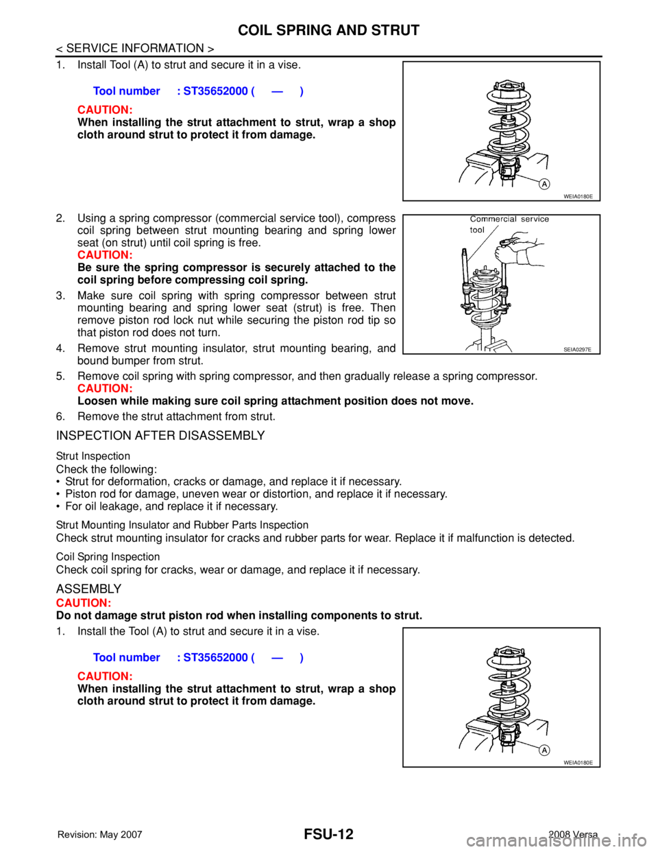
1. Install Tool (A) to strut and secure it in a vise.
CAUTION:
When installing the strut attachment to strut, wrap a shop
cloth around strut to protect it from damage.
2. Using a spring compressor (commercial service tool), compress
coil spring between strut mounting bearing and spring lower
seat (on strut) until coil spring is free.
CAUTION:
Be sure the spring compressor is securely attached to the
coil spring before compressing coil spring.
3. Make sure coil spring with spring compressor between strut
mounting bearing and spring lower seat (strut) is free. Then
remove piston rod lock nut while securing the piston rod tip so
that piston rod does not turn.
4. Remove strut mounting insulator, strut mounting bearing, and
bound bumper from strut.
5. Remove coil spring with spring compressor, and then gradually release a spring compressor.
CAUTION:
Loosen while making sure coil spring attachment position does not move.
6. Remove the strut attachment from strut.
INSPECTION AFTER DISASSEMBLY
Strut Inspection
Check the following:
• Strut for deformation, cracks or damage, and replace it if necessary.
• Piston rod for damage, uneven wear or distortion, and replace it if necessary.
• For oil leakage, and replace it if necessary.
Strut Mounting Insulator and Rubber Parts Inspection
Check strut mounting insulator for cracks and rubber parts for wear. Replace it if malfunction is detected.
Coil Spring Inspection
Check coil spring for cracks, wear or damage, and replace it if necessary.
ASSEMBLY
CAUTION:
Do not damage strut piston rod when installing components to strut.
1. Install the Tool (A) to strut and secure it in a vise.
CAUTION:
When installing the strut attachment to strut, wrap a shop
cloth around strut to protect it from damage.Tool number : ST35652000 ( — )
WEIA0180E
SEIA0297E
Tool number : ST35652000 ( — )
WEIA0180E
Page 1855 of 2771
GI-4
< SERVICE INFORMATION >
PRECAUTIONS
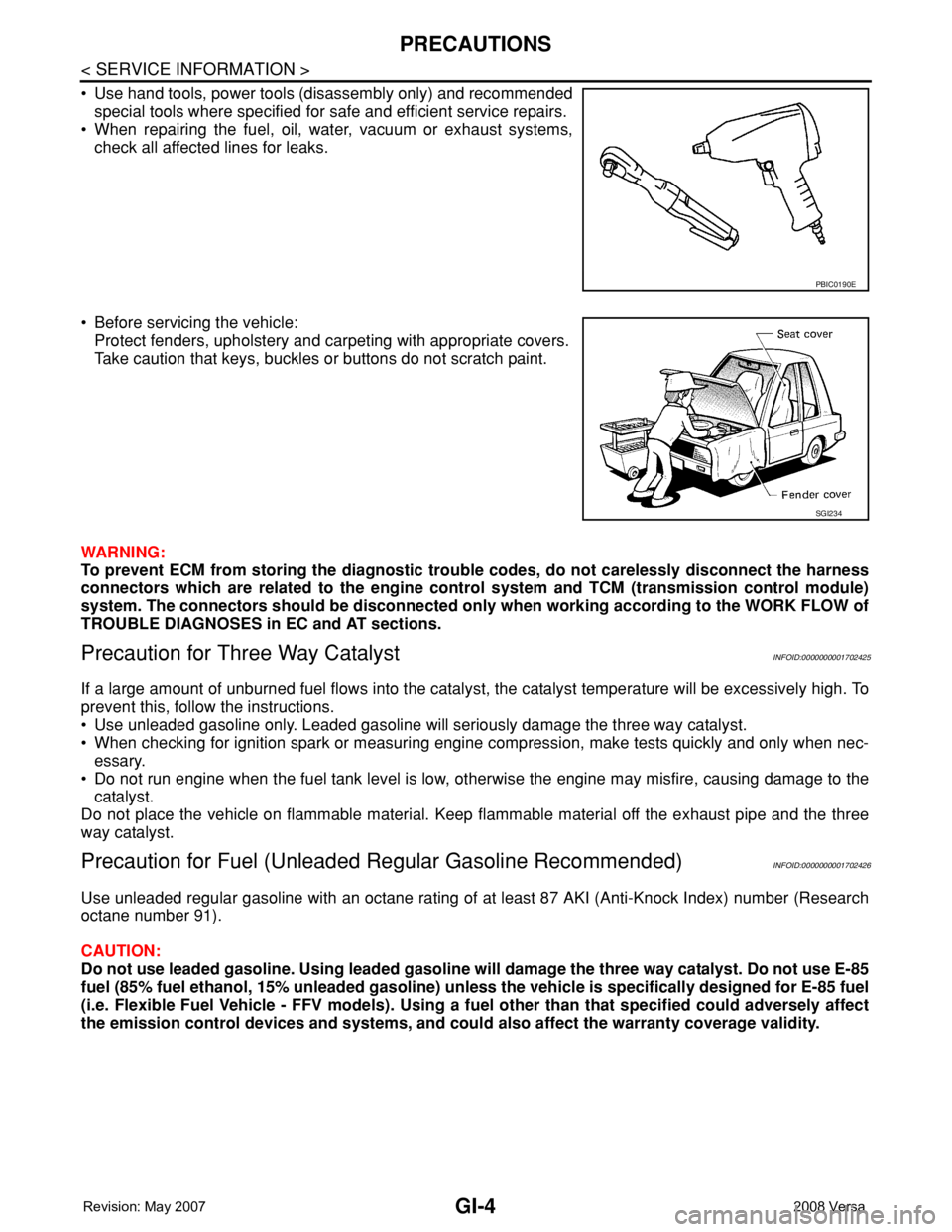
• Use hand tools, power tools (disassembly only) and recommended
special tools where specified for safe and efficient service repairs.
• When repairing the fuel, oil, water, vacuum or exhaust systems,
check all affected lines for leaks.
• Before servicing the vehicle:
Protect fenders, upholstery and carpeting with appropriate covers.
Take caution that keys, buckles or buttons do not scratch paint.
WARNING:
To prevent ECM from storing the diagnostic trouble codes, do not carelessly disconnect the harness
connectors which are related to the engine control system and TCM (transmission control module)
system. The connectors should be disconnected only when working according to the WORK FLOW of
TROUBLE DIAGNOSES in EC and AT sections.
Precaution for Three Way CatalystINFOID:0000000001702425
If a large amount of unburned fuel flows into the catalyst, the catalyst temperature will be excessively high. To
prevent this, follow the instructions.
• Use unleaded gasoline only. Leaded gasoline will seriously damage the three way catalyst.
• When checking for ignition spark or measuring engine compression, make tests quickly and only when nec-
essary.
• Do not run engine when the fuel tank level is low, otherwise the engine may misfire, causing damage to the
catalyst.
Do not place the vehicle on flammable material. Keep flammable material off the exhaust pipe and the three
way catalyst.
Precaution for Fuel (Unleaded Regular Gasoline Recommended)INFOID:0000000001702426
Use unleaded regular gasoline with an octane rating of at least 87 AKI (Anti-Knock Index) number (Research
octane number 91).
CAUTION:
Do not use leaded gasoline. Using leaded gasoline will damage the three way catalyst. Do not use E-85
fuel (85% fuel ethanol, 15% unleaded gasoline) unless the vehicle is specifically designed for E-85 fuel
(i.e. Flexible Fuel Vehicle - FFV models). Using a fuel other than that specified could adversely affect
the emission control devices and systems, and could also affect the warranty coverage validity.
PBIC0190E
SGI234
Page 1858 of 2771
HOW TO USE THIS MANUAL
GI-7
< SERVICE INFORMATION >
C
D
E
F
G
H
I
J
K
L
MB
GI
N
O
PHOW TO USE THIS MANUAL
DescriptionINFOID:0000000001702431
This volume explains “Removal, Disassembly, Installation, Inspection and Adjustment” and “Trouble Diag-
noses”.
Te r m sINFOID:0000000001702432
• The captions WARNING and CAUTION warn you of steps that must be followed to prevent personal injury
and/or damage to some part of the vehicle.
WARNING indicates the possibility of personal injury if instructions are not followed.
CAUTION indicates the possibility of component damage if instructions are not followed.
BOLD TYPED STATEMENTS except WARNING and CAUTION give you helpful information.
Standard value:Tolerance at inspection and adjustment.
Limit value:The maximum or minimum limit value that should not be exceeded at inspection and adjustment.
UnitsINFOID:0000000001702433
• The UNITS given in this manual are primarily expressed as the SI UNIT (International System of Unit), and
alternatively expressed in the metric system and in the yard/pound system.
Also with regard to tightening torque of bolts and nuts, there are descriptions both about range and about the
standard tightening torque.
“Example”
Range
Standard
ContentsINFOID:0000000001702434
•ALPHABETICAL INDEX is provided at the end of this manual so that you can rapidly find the item and page
you are searching for.
•A QUICK REFERENCE INDEX, a black tab (e.g. ) is provided on the first page. You can quickly find the
first page of each section by matching it to the section's black tab.
•THE CONTENTS are listed on the first page of each section.
•THE TITLE is indicated on the upper portion of each page and shows the part or system.
•THE PAGE NUMBER of each section consists of two or three letters which designate the particular section
and a number (e.g. “BR-5”).
•THE SMALL ILLUSTRATIONS show the important steps such as inspection, use of special tools, knacks of
work and hidden or tricky steps which are not shown in the previous large illustrations.
Assembly, inspection and adjustment procedures for the complicated units such as the automatic transaxle
or transmission, etc. are presented in a step-by-step format where necessary. Outer Socket Lock Nut : 59 - 78 N·m (6.0 - 8.0 kg-m, 43 - 58 ft-lb)
Drive Shaft Installation Bolt: 44.3 N·m (4.5 kg-m, 33 ft-lb)
Page 1902 of 2771
GW-1
BODY
C
D
E
F
G
H
J
K
L
M
SECTION GW
A
B
GW
N
O
P
CONTENTS
GLASSES, WINDOW SYSTEM & MIRRORS
SERVICE INFORMATION ............................3
PRECAUTIONS ...................................................3
Precaution for Supplemental Restraint System
(SRS) "AIR BAG" and "SEAT BELT PRE-TEN-
SIONER" ...................................................................
3
Precaution for Procedure without Cowl Top Cover ......3
Handling for Adhesive and Primer ............................3
PREPARATION ...................................................4
Commercial Service Tool ..........................................4
SQUEAK AND RATTLE TROUBLE DIAG-
NOSES ................................................................
5
Work Flow .................................................................5
Generic Squeak and Rattle Troubleshooting ............7
Diagnostic Worksheet ...............................................9
WINDSHIELD GLASS ........................................11
Removal and Installation .........................................11
OPERA WINDOW GLASS .................................13
Removal and Installation .........................................13
REAR WINDOW GLASS AND MOLDING .........15
Removal and Installation .........................................15
POWER WINDOW SYSTEM ..............................18
Component Parts and Harness Connector Loca-
tion ..........................................................................
18
System Description .................................................18
CAN Communication System Description ...............22
Schematic ...............................................................22
Wiring Diagram - WINDOW- ...................................23
Main Power Window and Door Lock/Unlock
Switch Harness Connector Terminal Layout ...........
26
Terminal and Reference Value for Main Power
Window and Door Lock/Unlock Switch ...................
27
Terminal and Reference Value for BCM .................28
Work Flow ...............................................................28
CONSULT-III Function (BCM) .................................28
Power Window Auto Operation Initialization ...........29
Trouble Diagnosis Symptom Chart ..........................29
BCM Power Supply and Ground Circuit Inspection
....
30
Main Power Window and Door Lock/Unlock
Switch Power Supply and Ground Circuit Inspec-
tion ...........................................................................
30
Front Power Window Motor LH Circuit Inspection ....31
Front Power Window RH Circuit Inspection (Pow-
er Window and Door Lock/Unlock Switch RH Op-
eration) ....................................................................
32
Front Power Window Motor RH Circuit Inspection ....32
Encoder Circuit Inspection .......................................34
Door Switch Check ..................................................36
Rear Power Window LH Circuit Inspection (Rear
Power Window Switch LH Operation) .....................
37
Rear Power Window RH Circuit Inspection (Rear
Power Window Switch RH Operation) .....................
38
Rear Power Window Motor LH Circuit Inspection ....38
Rear Power Window Motor RH Circuit Inspection ....40
FRONT DOOR GLASS AND REGULATOR .....42
Removal and Installation .........................................42
Disassembly and Assembly .....................................44
Inspection after Installation ......................................44
REAR DOOR GLASS AND REGULATOR .......46
Removal and Installation .........................................46
Disassembly and Assembly .....................................48
Inspection after Installation ......................................48
REAR WINDOW DEFOGGER ..........................49
Component Parts and Harness Connector Loca-
tion ...........................................................................
49
System Description ..................................................49
CAN Communication System Description ...............50
Wiring Diagram - DEF - ...........................................51
Terminal and Reference Value for BCM ..................52
Terminal and Reference Value for IPDM E/R ..........52
Work Flow ................................................................53
CONSULT-III Function (BCM) .................................53
Trouble Diagnosis Symptom Chart ..........................53
Page 1903 of 2771
GW-2
BCM Power Supply and Ground Circuit Inspection
...
54
Rear Window Defogger Switch Circuit Inspection ...54
Rear Window Defogger Circuit Inspection ..............55
Door Mirror Defogger Circuit Inspection .................58
Filament Check .......................................................59
Filament Repair ......................................................60
DOOR MIRROR .................................................62
Wiring Diagram - MIRROR - ...................................62
Removal and Installation .........................................63
Disassembly and Assembly ....................................63
INSIDE MIRROR ................................................65
Removal and Installation .........................................65