Page 267 of 2771
DISASSEMBLY
AT-255
< SERVICE INFORMATION >
D
E
F
G
H
I
J
K
L
MA
B
AT
N
O
P
a. Set manual shaft to “P” position to fix idler gear.
b. Unlock idler gear lock nut with pin punch.
c. Remove idler gear lock nut.
d. Remove idler gear with puller.
e. Remove reduction pinion gear.
f. Remove reduction pinion gear adjusting shim from reduction
pinion gear.
47. Remove bearing retainer fitting bolts, and then remove bearing
retainer (1) from transaxle case.
SAT037F
SAT061D
SCIA5380E
SCIA4880E
SCIA5909J
Page 268 of 2771
AT-256
< SERVICE INFORMATION >
DISASSEMBLY
48. Remove return spring (2) from parking shaft (3) using a flat-
bladed screwdriver.
(1): Parking pawl
•Inspect return spring (2), and replace if damaged or worn.
49. Draw out parking shaft (1), and then remove parking pawl (2)
from transaxle case.
•Inspect parking shaft (1) and parking pawl (2), and replace
if damaged or worn.
50. Remove parking actuator support (1) from transaxle case.
•Inspect parking actuator support (1), and replace if dam-
aged or worn.
51. Remove snap ring from transaxle case using a flat-bladed
screwdriver.
52. Remove governor cap from transaxle case.
53. Remove O-ring from governor cap.
54. Remove LH differential side oil seal from transaxle case using a
flat-bladed screwdriver.
CAUTION:
Be careful not to scratch transaxle case.
SCIA6996E
SCIA6997E
SCIA6998E
ATM0076D
Page 272 of 2771
AT-260
< SERVICE INFORMATION >
REPAIR FOR COMPONENT PARTS
9. Install detent spring on transaxle case.
10. Tighten detent spring fitting bolt to the specified torque. Refer to
"COMPONENTS".
Oil PumpINFOID:0000000001703379
COMPONENTS
DISASSEMBLY
1. Remove seal rings (1) from oil pump assembly (2).
SAT042F
1. Oil pump housing oil seal 2. Oil pump housing 3. Outer gear
4. Inner gear 5. Oil pump cover 6. Seal ring
Refer to GI section to make sure icons (symbol marks) in the figure. Refer to GI-8, "
Component".
SCIA5908J
SCIA7016E
Page 276 of 2771
AT-264
< SERVICE INFORMATION >
REPAIR FOR COMPONENT PARTS
DISASSEMBLY
1. Pilot filter 2. Control valve upper body 3. Steel ball
4. Separating plate 5. Control valve inter body 6. Steel ball
7. Support plate 8. Separating plate 9. Control valve lower body
10. Line pressure relief valve spring 11. Check ball 12. Torque converter pressure holding
spring
13. Solenoid valve assembly 14. Terminal body 15. O-ring
16. O-ring 17. O-ring 18. Oil strainer
Refer to GI section to make sure icons (symbol marks) in the figure. Refer to GI-8, "
Component".
SCIA5967J
Page 286 of 2771

AT-274
< SERVICE INFORMATION >
REPAIR FOR COMPONENT PARTS
DISASSEMBLY
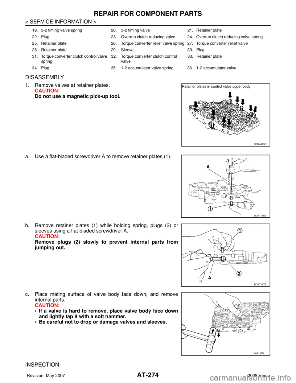
1. Remove valves at retainer plates.
CAUTION:
Do not use a magnetic pick-up tool.
a. Use a flat-bladed screwdriver A to remove retainer plates (1).
b. Remove retainer plates (1) while holding spring, plugs (2) or
sleeves using a flat-bladed screwdriver A.
CAUTION:
Remove plugs (2) slowly to prevent internal parts from
jumping out.
c. Place mating surface of valve body face down, and remove
internal parts.
CAUTION:
• If a valve is hard to remove, place valve body face down
and lightly tap it with a soft hammer.
• Be careful not to drop or damage valves and sleeves.
INSPECTION
19. 3-2 timing valve spring 20. 3-2 timing valve 21. Retainer plate
22. Plug 23. Overrun clutch reducing valve 24. Overrun clutch reducing valve spring
25. Retainer plate 26. Torque converter relief valve spring 27. Torque converter relief valve
28. Retainer plate 29. Sleeve 30. Plug
31. Torque converter clutch control valve
spring32. Torque converter clutch control
valve33. Retainer plate
34. Plug 35. 1-2 accumulator valve spring 36. 1-2 accumulator valve
SCIA4979E
SCIA7136E
SCIA7137E
SAT137D
Page 290 of 2771

AT-278
< SERVICE INFORMATION >
REPAIR FOR COMPONENT PARTS
DISASSEMBLY
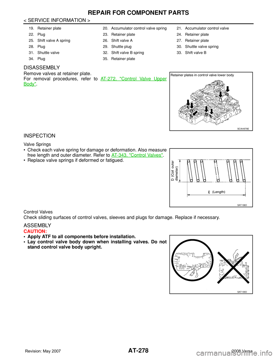
Remove valves at retainer plate.
For removal procedures, refer to AT-272, "
Control Valve Upper
Body".
INSPECTION
Valve Springs
• Check each valve spring for damage or deformation. Also measure
free length and outer diameter. Refer to AT-343, "
Control Valves".
• Replace valve springs if deformed or fatigued.
Control Valves
Check sliding surfaces of control valves, sleeves and plugs for damage. Replace if necessary.
ASSEMBLY
CAUTION:
• Apply ATF to all components before installation.
• Lay control valve body down when installing valves. Do not
stand control valve body upright.
19. Retainer plate 20. Accumulator control valve spring 21. Accumulator control valve
22. Plug 23. Retainer plate 24. Retainer plate
25. Shift valve A spring 26. Shift valve A 27. Retainer plate
28. Plug 29. Shuttle plug 30. Shuttle valve spring
31. Shuttle valve 32. Shift valve B spring 33. Shift valve B
34. Plug 35. Retainer plate
SCIA4978E
SAT138D
SAT139D
Page 291 of 2771

REPAIR FOR COMPONENT PARTS
AT-279
< SERVICE INFORMATION >
D
E
F
G
H
I
J
K
L
MA
B
AT
N
O
P
Install control valves.
For installation procedures, refer to AT-272, "
Control Valve Upper
Body".
Retainer Plate (Control Valve Lower Body)
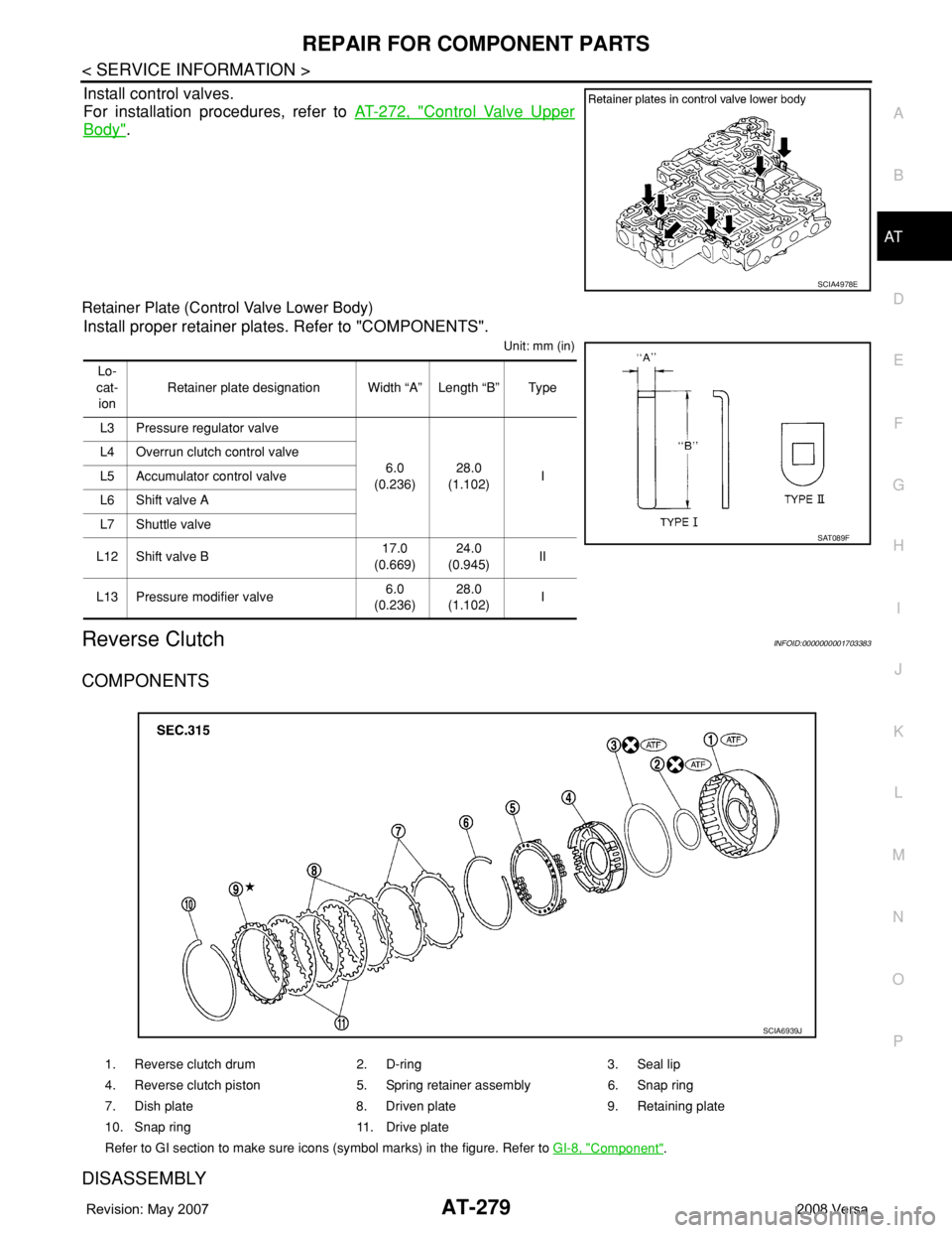
Install proper retainer plates. Refer to "COMPONENTS".
Unit: mm (in)
Reverse ClutchINFOID:0000000001703383
COMPONENTS
DISASSEMBLY
SCIA4978E
Lo-
cat-
ionRetainer plate designation Width “A” Length “B” Type
L3 Pressure regulator valve
6.0
(0.236)28.0
(1.102)I L4 Overrun clutch control valve
L5 Accumulator control valve
L6 Shift valve A
L7 Shuttle valve
L12 Shift valve B17.0
(0.669)24.0
(0.945)II
L13 Pressure modifier valve6.0
(0.236)28.0
(1.102)I
SAT089F
1. Reverse clutch drum 2. D-ring 3. Seal lip
4. Reverse clutch piston 5. Spring retainer assembly 6. Snap ring
7. Dish plate 8. Driven plate 9. Retaining plate
10. Snap ring 11. Drive plate
Refer to GI section to make sure icons (symbol marks) in the figure. Refer to GI-8, "
Component".
SCIA6939J
Page 296 of 2771

AT-284
< SERVICE INFORMATION >
REPAIR FOR COMPONENT PARTS
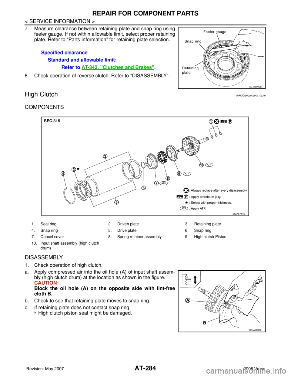
7. Measure clearance between retaining plate and snap ring using
feeler gauge. If not within allowable limit, select proper retaining
plate. Refer to “Parts Information” for retaining plate selection.
8. Check operation of reverse clutch. Refer to "DISASSEMBLY".
High ClutchINFOID:0000000001703384
COMPONENTS
DISASSEMBLY
1. Check operation of high clutch.
a. Apply compressed air into the oil hole (A) of input shaft assem-
bly (high clutch drum) at the location as shown in the figure.
CAUTION:
Block the oil hole (A) on the opposite side with lint-free
cloth B.
b. Check to see that retaining plate moves to snap ring.
c. If retaining plate does not contact snap ring:
• High clutch piston seal might be damaged.Specified clearance
Standard and allowable limit:
Refer to AT-343, "
Clutches and Brakes".
SCIA8009E
1. Seal ring 2. Driven plate 3. Retaining plate
4. Snap ring 5. Drive plate 6. Snap ring
7. Cancel cover 8. Spring retainer assembly 9. High clutch Piston
10. Input shaft assembly (high clutch
drum)
SCIA6741E
SCIA7032E