2008 NISSAN TIIDA PN switch
[x] Cancel search: PN switchPage 2228 of 2771

INTERIOR ROOM LAMP
LT-91
< SERVICE INFORMATION >
C
D
E
F
G
H
I
J
L
MA
B
LT
N
O
P
• to map lamp terminal 1
Power is supplied
• through BCM terminal 56
• to map lamp terminal 4.
When interior room lamp switch is ON, ground is supplied
• to interior room lamp terminal 1
• through map lamp (with map lamp) terminal 7
• through map lamp (with map lamp) terminal 1
• through grounds M57 and M61.
Power is supplied
• through BCM terminal 56
• through map lamp (with map lamp) terminal 4
• through map lamp (with map lamp) terminal 6
• to room lamp terminal 3.
INTERIOR ROOM LAMP TIMER OPERATION
Without Intelligent Key System
When room lamp switch is in DOOR position, and when all conditions below are met, BCM performs timer
control (maximum 30 seconds) for room lamp ON/OFF.
In addition, when the interior room lamp turns ON or OFF there is gradual brightening or dimming over 1 sec-
ond.
Power is supplied
• through 10A fuse [No. 14, located in fuse block (J/B)]
• to key switch and key lock solenoid terminal 2.
When the key is removed from ignition key cylinder (key switch OFF), power will not be supplied to BCM termi-
nal 37.
When front door key cylinder switch LH is unlocked, ground is supplied
• to BCM terminal 7
• through front door key cylinder switch LH terminal 3
• through front door key cylinder switch LH terminal 2
• through grounds M57 and M61.
At the time that front door LH is opened, BCM detects that front door LH is unlocked. It determines that interior
room lamp timer operation condition is met, and turns the room lamp ON for 30 seconds.
When key is in ignition key cylinder (key switch ON),
Power is supplied
• through key switch and key lock solenoid terminal 1
• to BCM terminal 37.
When key is removed from key switch and key lock solenoid (key switch OFF), the power supply to BCM ter-
minal 37 is terminated. BCM detects that key has been removed, determines that interior room lamp timer
conditions are met, and turns the room lamp ON for 30 seconds.
When front door LH opens → closes, and the key is not inserted in the key switch and key lock solenoid (key
switch OFF), voltage at BCM terminal 47 changes between 0V (door open) → 12V (door closed). The BCM
determines that conditions for room lamp operation are met and turns the room lamp ON for 30 seconds.
Interior room lamp timer control is canceled under the following conditions:
• Front door LH is locked (locked front door key cylinder switch LH).
• Front door LH is opened (front door switch LH).
• Ignition switch ON.
With Intelligent Key System
When the room lamp switch is in DOOR position, and when all conditions below are met, BCM performs timer
control (maximum 30 second) for room lamp ON/OFF.
In addition, when interior room lamp turns ON or OFF there is gradual brightening or dimming over 1 second.
Power is supplied
• through 10A fuse (No. 31, located in fuse and fusible link box)
• to key switch and ignition knob switch terminals 2 and 4.
When key is removed from ignition key cylinder (key switch OFF), power will not be supplied to BCM terminal
37.
When the ignition knob switch is released, power will not be supplied to Intelligent Key unit terminal 27.
When front door key cylinder switch LH is unlocked, ground is supplied
• to BCM terminal 7
• through front door key cylinder switch LH terminal 3
Page 2229 of 2771

LT-92
< SERVICE INFORMATION >
INTERIOR ROOM LAMP
• through front door key cylinder switch LH terminal 2
• through grounds M57 and M61.
At the time the front door LH is opened, the BCM detects the front door LH is unlocked. It determines that the
interior room lamp timer operation conditions are met, and interior room lamp ON for 30 seconds.
When the key is in ignition key cylinder (key switch ON), or ignition knob switch is pushed, power is supplied
• through key switch and ignition knob switch terminal 1
• to BCM terminal 37, or
• through key switch and ignition knob switch terminal 3
• to Intelligent Key unit terminal 27.
When the key is removed from key switch (key switch OFF), power supply to BCM terminal 37 is terminated.
When the ignition knob switch is released, power supply to intelligent key unit is terminated. The BCM detects
that the key has been removed, determines that interior room lamp timer conditions are met, and turns room
lamp ON for 30 seconds.
When the front door LH opens → closes, and key is not inserted in key switch (or ignition knob switch is
released), BCM terminal 47 changes between 0V (door open) → 12V (door closed). BCM determines that
conditions for room lamp operation are met, and turns room lamp ON for 30 seconds.
Interior room lamp timer control is canceled under the following conditions:
• Front door LH is locked (with keyfob or front door key cylinder switch LH).
• Front door LH is opened (front door switch LH).
• Ignition switch ON.
INTERIOR LAMP BATTERY SAVER CONTROL
If an interior room lamp is left ON, it will not be turned OFF even when door is closed.
BCM turns off interior lamp automatically to save battery 30 minutes after ignition switch is turned off.
After lamps are turned OFF by the battery saver system, the lamps illuminate again when
• front door key cylinder switch LH is locked or unlocked
• door is opened or closed
• key is removed from ignition key cylinder or inserted in ignition key cylinder, or the ignition knob switch is
pushed or released.
Interior lamp battery saver control time period can be changed by the function setting of CONSULT-III.
Page 2236 of 2771
INTERIOR ROOM LAMP
LT-99
< SERVICE INFORMATION >
C
D
E
F
G
H
I
J
L
MA
B
LT
N
O
P
3. Perform the preliminary check. Refer to LT-99, "Preliminary Check" .
4. Check symptom and repair or replace the cause of the malfunction.
5. Does the interior room lamp operate normally? If YES, GO TO 6. If NO, GO TO 4.
6. Inspection End
Preliminary CheckINFOID:0000000001704474
CHECK POWER SUPPLY AND GROUND CIRCUIT FOR BCM
Refer to BCS-15, "BCM Power Supply and Ground Circuit Inspection" .
CHECK POWER SUPPLY AND GROUND CIRCUIT FOR IPDM E/R
Refer to LT- 11 , "Preliminary Check" .
CONSULT-III Function (BCM)INFOID:0000000001704475
Refer to LT- 11 , "CONSULT-III Function (BCM)".
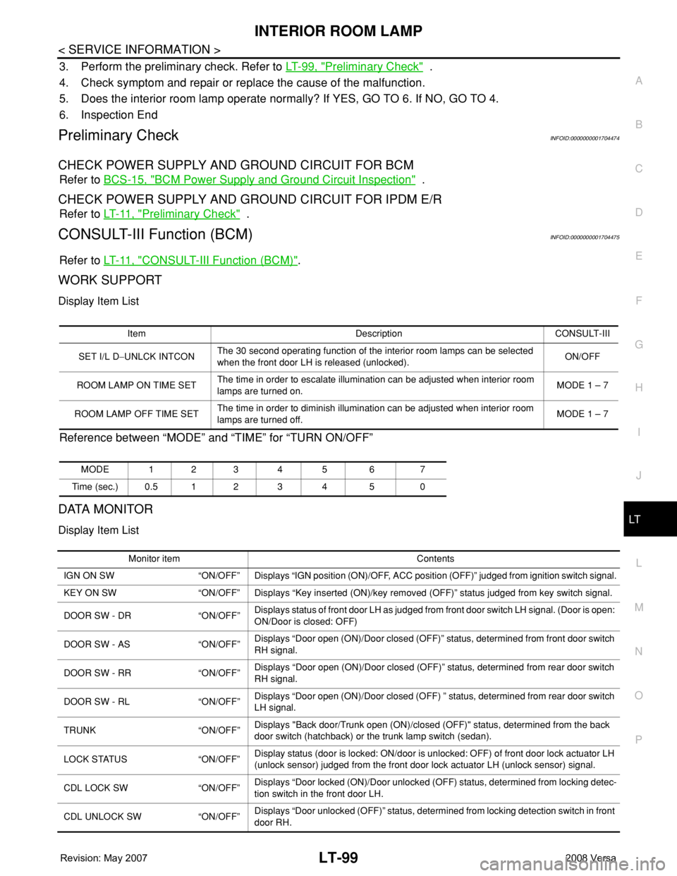
WORK SUPPORT
Display Item List
Reference between “MODE” and “TIME” for “TURN ON/OFF”
DATA MONITOR
Display Item List
Item Description CONSULT-III
SET I/L D−UNLCK INTCONThe 30 second operating function of the interior room lamps can be selected
when the front door LH is released (unlocked). ON/OFF
ROOM LAMP ON TIME SETThe time in order to escalate illumination can be adjusted when interior room
lamps are turned on.MODE 1 – 7
ROOM LAMP OFF TIME SETThe time in order to diminish illumination can be adjusted when interior room
lamps are turned off.MODE 1 – 7
MODE 123 4 5 6 7
Time (sec.) 0.5 1 2 3 4 5 0
Monitor item Contents
IGN ON SW “ON/OFF” Displays “IGN position (ON)/OFF, ACC position (OFF)” judged from ignition switch signal.
KEY ON SW “ON/OFF” Displays “Key inserted (ON)/key removed (OFF)” status judged from key switch signal.
DOOR SW - DR “ON/OFF”Displays status of front door LH as judged from front door switch LH signal. (Door is open:
ON/Door is closed: OFF)
DOOR SW - AS “ON/OFF”Displays “Door open (ON)/Door closed (OFF)” status, determined from front door switch
RH signal.
DOOR SW - RR “ON/OFF”Displays “Door open (ON)/Door closed (OFF)” status, determined from rear door switch
RH signal.
DOOR SW - RL “ON/OFF”Displays “Door open (ON)/Door closed (OFF) ” status, determined from rear door switch
LH signal.
TRUNK “ON/OFF”Displays "Back door/Trunk open (ON)/closed (OFF)" status, determined from the back
door switch (hatchback) or the trunk lamp switch (sedan).
LOCK STATUS “ON/OFF”Display status (door is locked: ON/door is unlocked: OFF) of front door lock actuator LH
(unlock sensor) judged from the front door lock actuator LH (unlock sensor) signal.
CDL LOCK SW “ON/OFF”Displays “Door locked (ON)/Door unlocked (OFF) status, determined from locking detec-
tion switch in the front door LH.
CDL UNLOCK SW “ON/OFF”Displays “Door unlocked (OFF)” status, determined from locking detection switch in front
door RH.
Page 2237 of 2771
LT-100
< SERVICE INFORMATION >
INTERIOR ROOM LAMP
NOTE:
Vehicles without intelligent key system display this item, but cannot be monitored.
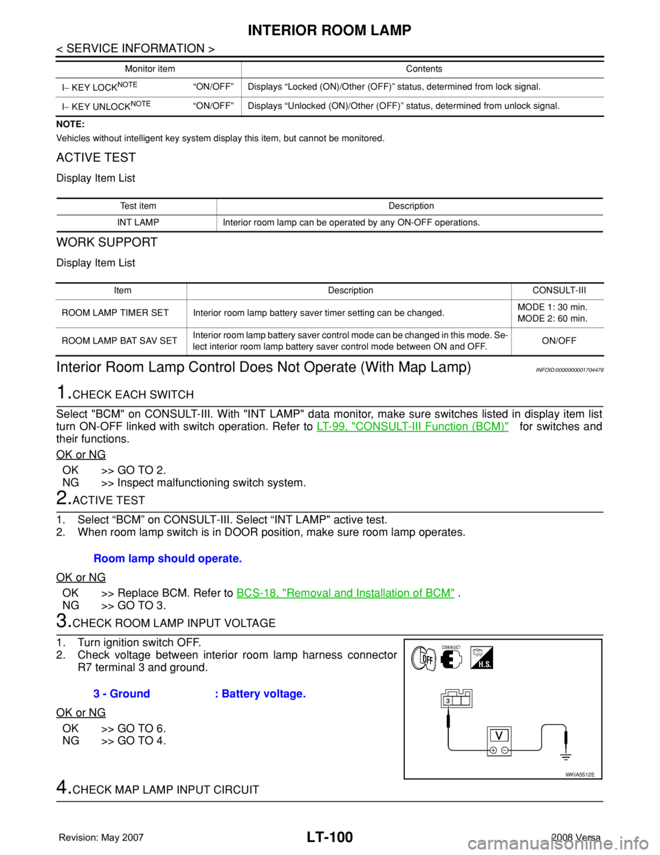
ACTIVE TEST
Display Item List
WORK SUPPORT
Display Item List
Interior Room Lamp Control Does Not Operate (With Map Lamp)INFOID:0000000001704476
1.CHECK EACH SWITCH
Select "BCM" on CONSULT-III. With "INT LAMP" data monitor, make sure switches listed in display item list
turn ON-OFF linked with switch operation. Refer to LT-99, "
CONSULT-III Function (BCM)" for switches and
their functions.
OK or NG
OK >> GO TO 2.
NG >> Inspect malfunctioning switch system.
2.ACTIVE TEST
1. Select “BCM” on CONSULT-III. Select “INT LAMP" active test.
2. When room lamp switch is in DOOR position, make sure room lamp operates.
OK or NG
OK >> Replace BCM. Refer to BCS-18, "Removal and Installation of BCM" .
NG >> GO TO 3.
3.CHECK ROOM LAMP INPUT VOLTAGE
1. Turn ignition switch OFF.
2. Check voltage between interior room lamp harness connector
R7 terminal 3 and ground.
OK or NG
OK >> GO TO 6.
NG >> GO TO 4.
4.CHECK MAP LAMP INPUT CIRCUIT
I− KEY LOCKNOTE“ON/OFF” Displays “Locked (ON)/Other (OFF)” status, determined from lock signal.
I− KEY UNLOCK
NOTE“ON/OFF” Displays “Unlocked (ON)/Other (OFF)” status, determined from unlock signal. Monitor item Contents
Test item Description
INT LAMP Interior room lamp can be operated by any ON-OFF operations.
Item Description CONSULT-III
ROOM LAMP TIMER SET Interior room lamp battery saver timer setting can be changed.MODE 1: 30 min.
MODE 2: 60 min.
ROOM LAMP BAT SAV SETInterior room lamp battery saver control mode can be changed in this mode. Se-
lect interior room lamp battery saver control mode between ON and OFF.ON/OFF
Room lamp should operate.
3 - Ground : Battery voltage.
WKIA5512E
Page 2238 of 2771
INTERIOR ROOM LAMP
LT-101
< SERVICE INFORMATION >
C
D
E
F
G
H
I
J
L
MA
B
LT
N
O
P
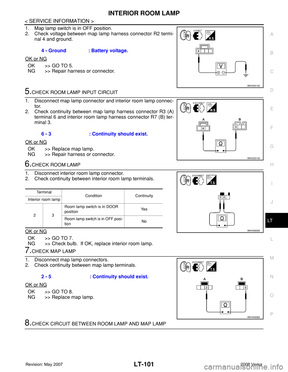
1. Map lamp switch is in OFF position.
2. Check voltage between map lamp harness connector R2 termi-
nal 4 and ground.
OK or NG
OK >> GO TO 5.
NG >> Repair harness or connector.
5.CHECK ROOM LAMP INPUT CIRCUIT
1. Disconnect map lamp connector and interior room lamp connec-
tor.
2. Check continuity between map lamp harness connector R3 (A)
terminal 6 and interior room lamp harness connector R7 (B) ter-
minal 3.
OK or NG
OK >> Replace map lamp.
NG >> Repair harness or connector.
6.CHECK ROOM LAMP
1. Disconnect interior room lamp connector.
2. Check continuity between interior room lamp terminals.
OK or NG
OK >> GO TO 7.
NG >> Check bulb. If OK, replace interior room lamp.
7.CHECK MAP LAMP
1. Disconnect map lamp connectors.
2. Check continuity between map lamp terminals.
OK or NG
OK >> GO TO 8.
NG >> Replace map lamp.
8.CHECK CIRCUIT BETWEEN ROOM LAMP AND MAP LAMP 4 - Ground : Battery voltage.
WKIA5513E
6 - 3 : Continuity should exist.
WKIA5514E
Te r m i n a l
Condition Continuity
Interior room lamp
23Room lamp switch is in DOOR
positionYe s
Room lamp switch is in OFF posi-
tionNo
WKIA5609E
2 - 5 : Continuity should exist.
WKIA5608E
Page 2239 of 2771
LT-102
< SERVICE INFORMATION >
INTERIOR ROOM LAMP
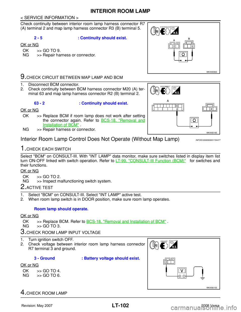
Check continuity between interior room lamp harness connector R7
(A) terminal 2 and map lamp harness connector R3 (B) terminal 5.
OK or NG
OK >> GO TO 9.
NG >> Repair harness or connector.
9.CHECK CIRCUIT BETWEEN MAP LAMP AND BCM
1. Disconnect BCM connector.
2. Check continuity between BCM harness connector M20 (A) ter-
minal 63 and map lamp harness connector R2 (B) terminal 2.
OK or NG
OK >> Replace BCM if room lamp does not work after setting
the connector again. Refer to BCS-18, "
Removal and
Installation of BCM" .
NG >> Repair harness or connector.
Interior Room Lamp Control Does Not Operate (Without Map Lamp)INFOID:0000000001704477
1.CHECK EACH SWITCH
Select "BCM" on CONSULT-III. With "INT LAMP" data monitor, make sure switches listed in display item list
turn ON-OFF linked with switch operation. Refer to LT-99, "
CONSULT-III Function (BCM)" for switches and
their functions.
OK or NG
OK >> GO TO 2.
NG >> Inspect malfunctioning switch system.
2.ACTIVE TEST
1. Select "BCM" on CONSULT-III. Select "INT LAMP" active test.
2. When room lamp switch is in DOOR position, make sure room lamp operates.
OK or NG
OK >> Replace BCM. Refer to BCS-18, "Removal and Installation of BCM" .
NG >> GO TO 3.
3.CHECK ROOM LAMP INPUT VOLTAGE
1. Turn ignition switch OFF.
2. Check voltage between interior room lamp harness connector
R7 terminal 3 and ground.
OK or NG
OK >> GO TO 4.
NG >> GO TO 6.
4.CHECK ROOM LAMP 2 - 5 : Continuity should exist.
WKIA5556E
63 - 2 : Continuity should exist.
WKIA5518E
Room lamp should operate.
3 - Ground : Battery voltage should exist.
WKIA5610E
Page 2240 of 2771
INTERIOR ROOM LAMP
LT-103
< SERVICE INFORMATION >
C
D
E
F
G
H
I
J
L
MA
B
LT
N
O
P
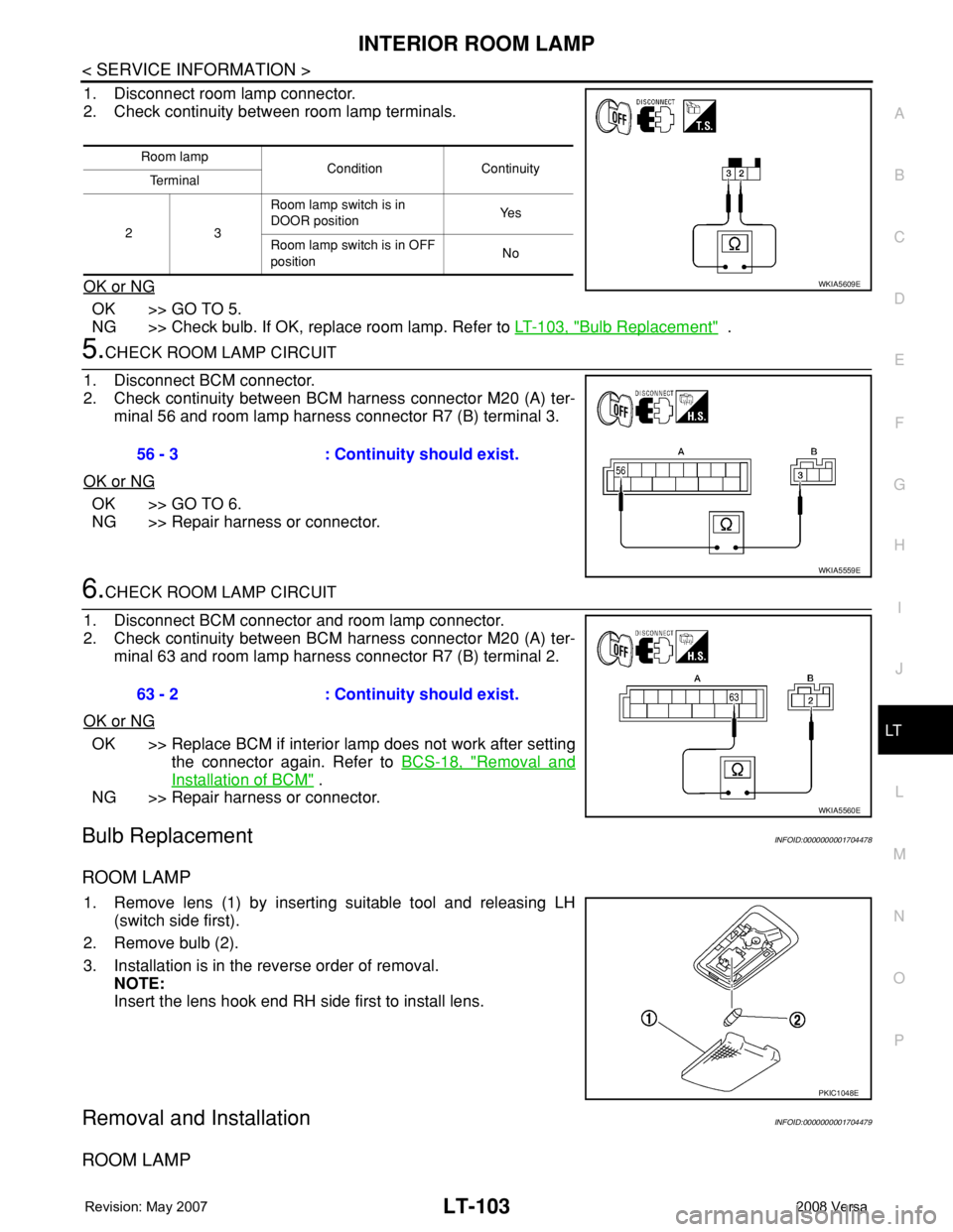
1. Disconnect room lamp connector.
2. Check continuity between room lamp terminals.
OK or NG
OK >> GO TO 5.
NG >> Check bulb. If OK, replace room lamp. Refer to LT-103, "
Bulb Replacement" .
5.CHECK ROOM LAMP CIRCUIT
1. Disconnect BCM connector.
2. Check continuity between BCM harness connector M20 (A) ter-
minal 56 and room lamp harness connector R7 (B) terminal 3.
OK or NG
OK >> GO TO 6.
NG >> Repair harness or connector.
6.CHECK ROOM LAMP CIRCUIT
1. Disconnect BCM connector and room lamp connector.
2. Check continuity between BCM harness connector M20 (A) ter-
minal 63 and room lamp harness connector R7 (B) terminal 2.
OK or NG
OK >> Replace BCM if interior lamp does not work after setting
the connector again. Refer to BCS-18, "
Removal and
Installation of BCM" .
NG >> Repair harness or connector.
Bulb ReplacementINFOID:0000000001704478
ROOM LAMP
1. Remove lens (1) by inserting suitable tool and releasing LH
(switch side first).
2. Remove bulb (2).
3. Installation is in the reverse order of removal.
NOTE:
Insert the lens hook end RH side first to install lens.
Removal and InstallationINFOID:0000000001704479
ROOM LAMP
Room lamp
Condition Continuity
Te r m i n a l
23 Room lamp switch is in
DOOR positionYe s
Room lamp switch is in OFF
positionNo
WKIA5609E
56 - 3 : Continuity should exist.
WKIA5559E
63 - 2 : Continuity should exist.
WKIA5560E
PKIC1048E
Page 2242 of 2771

ILLUMINATION
LT-105
< SERVICE INFORMATION >
C
D
E
F
G
H
I
J
L
MA
B
LT
N
O
P
ILLUMINATION
System DescriptionINFOID:0000000001704480
The control of the illumination lamps operation is dependent upon the position of the lighting switch. When the
lighting switch is placed in the 1ST or 2ND position, the BCM (body control module) receives input signal
requesting the illumination lamps to illuminate. This input signal is communicated to IPDM E/R (intelligent
power distribution module engine room) across CAN communication lines. CPU (central processing unit)
located in the IPDM E/R controls the tail lamp relay coil. This relay, when energized, directs power to the illu-
mination lamps, which then illuminate.
Power is supplied at all times
• to ignition relay, located in IPDM E/R,
• to tail lamp relay, located in IPDM E/R,
• through 15A fuse (No. 52, located in IPDM E/R) and
• through 20A fuse (No. 53, located in IPDM E/R)
• to CPU located in IPDM E/R,
• through 40A fusible link (letter g , located in fuse and fusible link box)
• to BCM terminal 70, and
• through 10A fuse [No. 8, located in fuse block (J/B)]
• to BCM terminal 57.
With the ignition switch in the ON or START position, power is supplied
• to ignition relay, located in IPDM E/R, and
• through 10A fuse [No. 6, located in fuse block (J/B)]
• to BCM terminal 38.
With the ignition switch in the ACC or ON position, power is supplied
• through 10A fuse [No. 20, located in fuse block (J/B)]
• to BCM terminal 11.
Ground is supplied
• to BCM terminal 67
• through grounds M57 and M61, and
• to IPDM E/R terminals 39 and 59
• through grounds E15 and E24.
ILLUMINATION OPERATION BY LIGHTING SWITCH
With the lighting switch in the 1ST or 2ND position, BCM receives input signal requesting the illumination
lamps to illuminate. This input signal is communicated to IPDM E/R across CAN communication lines. CPU
located in the IPDM E/R controls the tail lamp relay coil, which, when energized, directs power
• through 10A fuse (No. 37, located in IPDM E/R)
• through IPDM E/R terminal 29
• to microphone terminal 3 (with Bluetooth)
• to illumination control switch terminal 1
• to glove box lamp terminal 1 (with glovebox lamp)
• to audio unit terminal 9
• to front air control terminal 5
• to A/T device terminal 3 (with 4-speed A/T)
• to CVT device terminal 3 (with CVT)
• to hazard switch terminal 3
• to combination meter terminal 12
• to door mirror remote control switch terminal 16, and
Ground is supplied
• to microphone terminal 2 (with Bluetooth)
• to glove box lamp terminal 2 (with glove box lamp), and
• to illumination control switch terminal 3
• through grounds M57 and M61.
The illumination control switch controls illumination intensity by varying the ground to the following
• through illumination control switch terminal 2
• to audio unit terminal 8
• to front air control terminal 6
• to A/T device terminal 4 (with 4-speed A/T)
• to CVT device terminal 3 (with CVT)
• to hazard switch terminal 4