2008 NISSAN TIIDA PN switch
[x] Cancel search: PN switchPage 2182 of 2771
FRONT FOG LAMP
LT-45
< SERVICE INFORMATION >
C
D
E
F
G
H
I
J
L
MA
B
LT
N
O
P
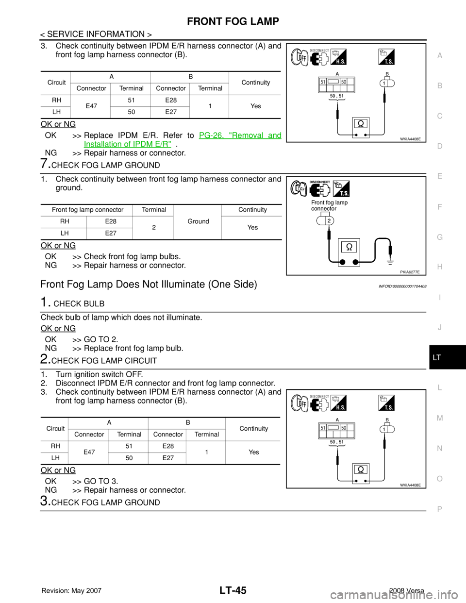
3. Check continuity between IPDM E/R harness connector (A) and
front fog lamp harness connector (B).
OK or NG
OK >> Replace IPDM E/R. Refer to PG-26, "Removal and
Installation of IPDM E/R" .
NG >> Repair harness or connector.
7.CHECK FOG LAMP GROUND
1. Check continuity between front fog lamp harness connector and
ground.
OK or NG
OK >> Check front fog lamp bulbs.
NG >> Repair harness or connector.
Front Fog Lamp Does Not Illuminate (One Side)INFOID:0000000001704408
1. CHECK BULB
Check bulb of lamp which does not illuminate.
OK or NG
OK >> GO TO 2.
NG >> Replace front fog lamp bulb.
2.CHECK FOG LAMP CIRCUIT
1. Turn ignition switch OFF.
2. Disconnect IPDM E/R connector and front fog lamp connector.
3. Check continuity between IPDM E/R harness connector (A) and
front fog lamp harness connector (B).
OK or NG
OK >> GO TO 3.
NG >> Repair harness or connector.
3.CHECK FOG LAMP GROUND
CircuitAB
Continuity
Connector Terminal Connector Terminal
RH
E4751 E28
1Yes
LH 50 E27
WKIA4408E
Front fog lamp connector Terminal
Ground Continuity
RH E28
2Yes
LH E27
PKIA6277E
CircuitAB
Continuity
Connector Terminal Connector Terminal
RH
E4751 E28
1Yes
LH 50 E27
WKIA4408E
Page 2184 of 2771
FRONT FOG LAMP
LT-47
< SERVICE INFORMATION >
C
D
E
F
G
H
I
J
L
MA
B
LT
N
O
P
Bulb ReplacementINFOID:0000000001704410
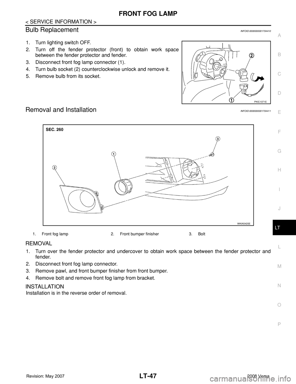
1. Turn lighting switch OFF.
2. Turn off the fender protector (front) to obtain work space
between the fender protector and fender.
3. Disconnect front fog lamp connector (1).
4. Turn bulb socket (2) counterclockwise unlock and remove it.
5. Remove bulb from its socket.
Removal and InstallationINFOID:0000000001704411
REMOVAL
1. Turn over the fender protector and undercover to obtain work space between the fender protector and
fender.
2. Disconnect front fog lamp connector.
3. Remove pawl, and front bumper finisher from front bumper.
4. Remove bolt and remove front fog lamp from bracket.
INSTALLATION
Installation is in the reverse order of removal.
PKIC1071E
1. Front fog lamp 2. Front bumper finisher 3. Bolt
WKIA5420E
Page 2185 of 2771
LT-48
< SERVICE INFORMATION >
TURN SIGNAL AND HAZARD WARNING LAMPS
TURN SIGNAL AND HAZARD WARNING LAMPS
Component Parts and Harness Connector LocationINFOID:0000000001704412
System DescriptionINFOID:0000000001704413
TURN SIGNAL OPERATION
Power is supplied at all times
• through 40A fusible link (letter g , located in the fuse and fusible link box)
• to BCM (body control module) terminal 70,
• through 10A fuse [No. 8, located in the fuse block (J/B)]
• to BCM terminal 57,
• through 10A fuse [No. 13, located in the fuse block (J/B)]
• to combination meter terminal 27.
With the ignition switch in the ON or START position, power is supplied
• through 10A fuse [No. 6, located in fuse block (J/B)]
• to BCM terminal 38,
• through 10A fuse [No. 3, located in fuse block (J/B)]
• to combination meter terminal 28.
With the ignition switch in the ACC or ON position, power is supplied
• through 10A fuse [No. 20, located in the fuse block (J/B)]
• to BCM terminal 11.
Ground is supplied
• to BCM terminal 67 and
• to combination meter terminals 21, 22 and 23
• through grounds M57 and M61.
LH Turn Signal Lamp
When the turn signal switch is moved to the left turn position, the BCM receives an input signal requesting left
turn signals to flash. The BCM then supplies power
• through BCM terminal 60
• to front combination lamp LH terminal 4 and
• to rear combination lamp LH terminal 6.
Ground is supplied
• to front combination lamp LH terminal 5
• through grounds E15 and E24,
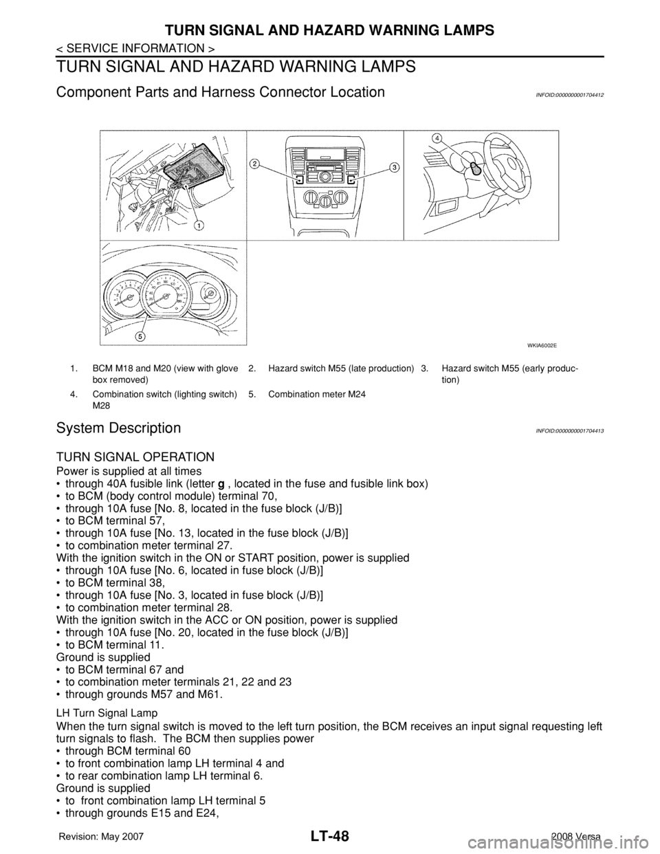
1. BCM M18 and M20 (view with glove
box removed)2. Hazard switch M55 (late production) 3. Hazard switch M55 (early produc-
tion)
4. Combination switch (lighting switch)
M285. Combination meter M24
WKIA6002E
Page 2186 of 2771

TURN SIGNAL AND HAZARD WARNING LAMPS
LT-49
< SERVICE INFORMATION >
C
D
E
F
G
H
I
J
L
MA
B
LT
N
O
P
• to rear combination lamp LH terminal 1
• through grounds B7 and B19.
The BCM also sends a request, via the CAN communication lines, to the combination meter to flash the left
turn signal indicator. The unified meter control unit in the combination meter supplies ground to the left turn
signal indicator lamp and activates the audible turn signal indicator.
With power, ground and input supplied, the BCM controls the flashing of the turn signal lamps.
RH Turn Signal Lamp
When turn signal switch is moved to the right turn position, the BCM receives an input signal requesting right
turn signals to flash. The BCM then supplies power
• through BCM terminal 61
• to front combination lamp RH terminal 4 and
• to rear combination lamp RH terminal 6.
Ground is supplied
• to front combination lamp RH terminal 5
• through grounds E15 and E24,
• to rear combination lamp RH terminal 1
• through grounds B117, B132 (all models) and D402 (with hatchback).
The BCM also sends a request, via the CAN communication lines, to the combination meter to flash the right
turn signal indicator. The unified meter control unit in the combination meter supplies ground to the right turn
signal indicator lamp and activates the audible turn signal indicator.
With power, ground and input supplied, the BCM controls the flashing of the turn signal lamps.
HAZARD LAMP OPERATION
Power is supplied at all times
• through 40A fusible link (letter g , located in fuse, fusible link and relay box)
• to BCM terminal 70,
• through 10A fuse [No. 8, located in fuse block (J/B)]
• to BCM terminal 57,
• through 10A fuse [No. 13, located in fuse block (J/B)]
• to combination meter terminal 27.
Ground is supplied
• to hazard switch terminal 1,
• to BCM terminal 67, and
• to combination meter terminals 21, 22 and 23
• through grounds M57 and M61.
When hazard switch is depressed, ground is supplied
• through hazard switch terminal 2
• to BCM terminal 29.
BCM then supplies power
• to front combination lamp LH terminal 4 and
• to rear combination lamp LH terminal 6
• through BCM terminal 60,
• to front combination lamp RH terminal 4 and
• to rear combination lamp RH terminal 6
• through BCM terminal 61.
Ground is supplied
• to front combination lamp LH and RH terminal 5
• through grounds E15 and E24,
• to rear combination lamp LH terminal 1
• through grounds B7 and B19,
• to rear combination lamp RH terminal 1
• through grounds B117, B132 and D402 (hatchback).
The BCM also supplies input to combination meter across the CAN communication lines. This input is pro-
cessed by unified meter control unit in combination meter, which in turn supplies ground to the left and right
turn signal indicator lamps.
With power and input supplied, BCM controls flashing of hazard warning lamps.
REMOTE KEYLESS ENTRY SYSTEM OPERATION
Power is supplied at all times
• through 40A fusible link (letter g , located in fuse, fusible link and relay box)
• to BCM terminal 70,
Page 2187 of 2771
![NISSAN TIIDA 2008 Service Repair Manual LT-50
< SERVICE INFORMATION >
TURN SIGNAL AND HAZARD WARNING LAMPS
• through 10A fuse [No. 13, located in fuse block (J/B)]
• to combination meter terminal 27.
Ground is supplied
• to BCM termin NISSAN TIIDA 2008 Service Repair Manual LT-50
< SERVICE INFORMATION >
TURN SIGNAL AND HAZARD WARNING LAMPS
• through 10A fuse [No. 13, located in fuse block (J/B)]
• to combination meter terminal 27.
Ground is supplied
• to BCM termin](/manual-img/5/57399/w960_57399-2186.png)
LT-50
< SERVICE INFORMATION >
TURN SIGNAL AND HAZARD WARNING LAMPS
• through 10A fuse [No. 13, located in fuse block (J/B)]
• to combination meter terminal 27.
Ground is supplied
• to BCM terminal 67 and
• to combination meter terminals 21, 22 and 23
• through grounds M57 and M61.
When the remote keyless entry system is triggered by input from the keyfob, the BCM supplies power
• through BCM terminal 60
• to front combination lamp LH terminal 4 and
• to rear combination lamp LH terminal 6,
• through BCM terminal 61
• to front turn signal lamp RH terminal 4 and
• to rear combination lamp RH terminal 6.
Ground is supplied
• to front combination lamp LH and RH terminals 5
• through grounds E15 and E24,
• to rear combination lamp LH terminal 1
• through grounds B7 and B19,
• to rear combination lamp RH terminal 1
• through grounds B117, B132 (all models) and D402 (with hatchback).
The BCM also supplies input to combination meter via the CAN communication lines. This input is processed
by the unified meter control unit in combination meter, which in turn supplies ground to the left and right turn
signal indicator lamps.
With power and ground supplied, BCM controls flashing of hazard warning lamps when keyfob is used to acti-
vate remote keyless entry system.
COMBINATION SWITCH READING FUNCTION
Refer to BCS-3, "System Description" .
CAN Communication System DescriptionINFOID:0000000001704414
Refer to LAN-6, "System Description" .
Page 2193 of 2771
LT-56
< SERVICE INFORMATION >
TURN SIGNAL AND HAZARD WARNING LAMPS
3. Perform the preliminary check. Refer to LT-56, "Preliminary Check" .
4. Check symptom and repair or replace the cause of the malfunction.
5. Do turn signal and hazard warning lamps operate normally? If YES, GO TO 6. If NO, GO TO 4.
6. INSPECTION END
Preliminary CheckINFOID:0000000001704419
CHECK POWER SUPPLY AND GROUND CIRCUIT FOR BCM
Refer to BCS-15, "BCM Power Supply and Ground Circuit Inspection" .
CONSULT-III Function (BCM)INFOID:0000000001704420
Refer to LT- 11 , "CONSULT-III Function (BCM)" .
Turn Signals Do Not OperateINFOID:0000000001704421
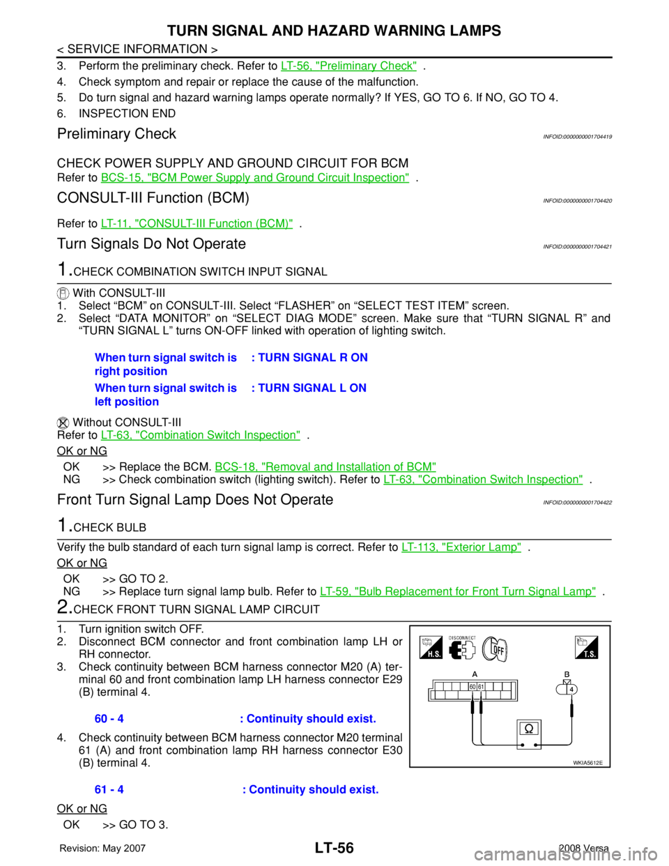
1.CHECK COMBINATION SWITCH INPUT SIGNAL
With CONSULT-III
1. Select “BCM” on CONSULT-III. Select “FLASHER” on “SELECT TEST ITEM” screen.
2. Select “DATA MONITOR” on “SELECT DIAG MODE” screen. Make sure that “TURN SIGNAL R” and
“TURN SIGNAL L” turns ON-OFF linked with operation of lighting switch.
Without CONSULT-III
Refer to LT-63, "
Combination Switch Inspection" .
OK or NG
OK >> Replace the BCM. BCS-18, "Removal and Installation of BCM"
NG >> Check combination switch (lighting switch). Refer to LT-63, "Combination Switch Inspection" .
Front Turn Signal Lamp Does Not OperateINFOID:0000000001704422
1.CHECK BULB
Verify the bulb standard of each turn signal lamp is correct. Refer to LT-113, "
Exterior Lamp" .
OK or NG
OK >> GO TO 2.
NG >> Replace turn signal lamp bulb. Refer to LT-59, "
Bulb Replacement for Front Turn Signal Lamp" .
2.CHECK FRONT TURN SIGNAL LAMP CIRCUIT
1. Turn ignition switch OFF.
2. Disconnect BCM connector and front combination lamp LH or
RH connector.
3. Check continuity between BCM harness connector M20 (A) ter-
minal 60 and front combination lamp LH harness connector E29
(B) terminal 4.
4. Check continuity between BCM harness connector M20 terminal
61 (A) and front combination lamp RH harness connector E30
(B) terminal 4.
OK or NG
OK >> GO TO 3.When turn signal switch is
right position: TURN SIGNAL R ON
When turn signal switch is
left position: TURN SIGNAL L ON
60 - 4 : Continuity should exist.
61 - 4 : Continuity should exist.
WKIA5612E
Page 2194 of 2771
TURN SIGNAL AND HAZARD WARNING LAMPS
LT-57
< SERVICE INFORMATION >
C
D
E
F
G
H
I
J
L
MA
B
LT
N
O
P
NG >> Repair harness or connector.
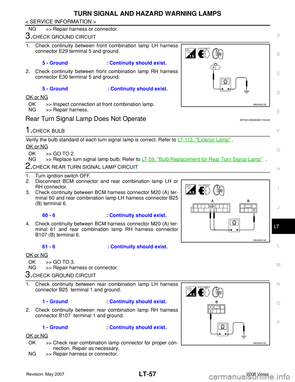
3.CHECK GROUND CIRCUIT
1. Check continuity between front combination lamp LH harness
connector E29 terminal 5 and ground.
2. Check continuity between front combination lamp RH harness
connector E30 terminal 5 and ground.
OK or NG
OK >> Inspect connection at front combination lamp.
NG >> Repair harness.
Rear Turn Signal Lamp Does Not OperateINFOID:0000000001704423
1.CHECK BULB
Verify the bulb standard of each turn signal lamp is correct. Refer to LT-113, "
Exterior Lamp" .
OK or NG
OK >> GO TO 2.
NG >> Replace turn signal lamp bulb. Refer to LT-59, "
Bulb Replacement for Rear Turn Signal Lamp" .
2.CHECK REAR TURN SIGNAL LAMP CIRCUIT
1. Turn ignition switch OFF.
2. Disconnect BCM connector and rear combination lamp LH or
RH connector.
3. Check continuity between BCM harness connector M20 (A) ter-
minal 60 and rear combination lamp LH harness connector B25
(B) terminal 6.
4. Check continuity between BCM harness connector M20 (A) ter-
minal 61 and rear combination lamp RH harness connector
B107 (B) terminal 6.
OK or NG
OK >> GO TO 3.
NG >> Repair harness or connector.
3.CHECK GROUND CIRCUIT
1. Check continuity between rear combination lamp LH harness
connector B25 terminal 1 and ground.
2. Check continuity between rear combination lamp RH harness
connector B107 terminal 1 and ground.
OK or NG
OK >> Check rear combination lamp connector for proper con-
nection. Repair as necessary.
NG >> Repair harness or connector.5 - Ground : Continuity should exist.
5 - Ground : Continuity should exist.
WKIA5613E
60 - 6 : Continuity should exist.
61 - 6 : Continuity should exist.
WKIA5614E
1 - Ground : Continuity should exist.
1 - Ground : Continuity should exist.
WKIA5615E
Page 2195 of 2771
LT-58
< SERVICE INFORMATION >
TURN SIGNAL AND HAZARD WARNING LAMPS
Hazard Warning Lamp Does Not Operate But Turn Signal Lamp Operates
INFOID:0000000001704424
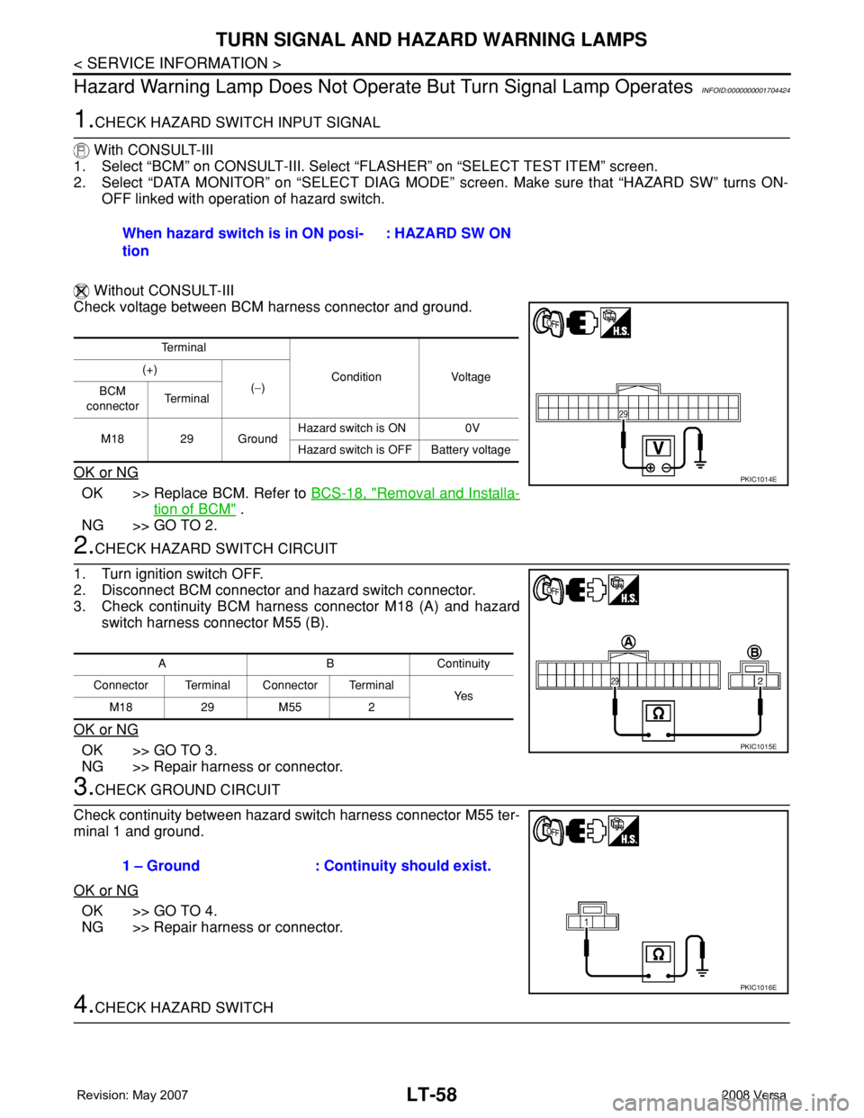
1.CHECK HAZARD SWITCH INPUT SIGNAL
With CONSULT-III
1. Select “BCM” on CONSULT-III. Select “FLASHER” on “SELECT TEST ITEM” screen.
2. Select “DATA MONITOR” on “SELECT DIAG MODE” screen. Make sure that “HAZARD SW” turns ON-
OFF linked with operation of hazard switch.
Without CONSULT-III
Check voltage between BCM harness connector and ground.
OK or NG
OK >> Replace BCM. Refer to BCS-18, "Removal and Installa-
tion of BCM" .
NG >> GO TO 2.
2.CHECK HAZARD SWITCH CIRCUIT
1. Turn ignition switch OFF.
2. Disconnect BCM connector and hazard switch connector.
3. Check continuity BCM harness connector M18 (A) and hazard
switch harness connector M55 (B).
OK or NG
OK >> GO TO 3.
NG >> Repair harness or connector.
3.CHECK GROUND CIRCUIT
Check continuity between hazard switch harness connector M55 ter-
minal 1 and ground.
OK or NG
OK >> GO TO 4.
NG >> Repair harness or connector.
4.CHECK HAZARD SWITCHWhen hazard switch is in ON posi-
tion : HAZARD SW ON
Te r m i n a l
Condition Voltage (+)
(−)
BCM
connectorTe r m i n a l
M18 29 GroundHazard switch is ON 0V
Hazard switch is OFF Battery voltage
PKIC1014E
ABContinuity
Connector Terminal Connector Terminal
Ye s
M18 29 M55 2
PKIC1015E
1 – Ground : Continuity should exist.
PKIC1016E