2008 NISSAN TIIDA PN switch
[x] Cancel search: PN switchPage 2210 of 2771
PARKING, LICENSE PLATE AND TAIL LAMPS
LT-73
< SERVICE INFORMATION >
C
D
E
F
G
H
I
J
L
MA
B
LT
N
O
P
• to front combination lamp RH terminal 6,
• through IPDM E/R terminal 28
• to rear combination lamp LH terminal 4 and
• to license plate lamp LH and RH terminal 1,
• through IPDM E/R terminal 29
• to rear combination lamp RH terminal 4.
Ground is supplied
• to front combination lamp LH and RH terminal 7
• through grounds E15 and E24,
• to rear combination lamp LH terminal 1 and
• to license plate lamp LH and RH terminal 2
• through grounds B7 and B19, and
• to rear combination lamp RH terminal 1
• through grounds B117, B132 (all models) and D402 (with hatchback).
With power and ground supplied, parking, license plate and tail lamps illuminate.
COMBINATION SWITCH READING FUNCTION
Refer to BCS-3, "System Description" .
EXTERIOR LAMP BATTERY SAVER CONTROL
When the combination switch (lighting switch) is in the 1ST (or 2ND) position and the ignition switch is turned
from ON or ACC to OFF, the battery saver control feature is activated.
Under this condition, the parking, license and tail lamps remain illuminated for 5 minutes, then the parking,
license plate and tail lamps are turned off.
Exterior lamp battery saver control mode can be changed by the function setting of CONSULT-III.
CAN Communication System DescriptionINFOID:0000000001704449
Refer to LAN-6, "System Description" .
Page 2216 of 2771
PARKING, LICENSE PLATE AND TAIL LAMPS
LT-79
< SERVICE INFORMATION >
C
D
E
F
G
H
I
J
L
MA
B
LT
N
O
P
How to Proceed with Trouble DiagnosisINFOID:0000000001704454
1. Confirm the symptom or customer complaint.
2. Understand operation description and function description. Refer to LT-72, "
System Description" .
3. Perform the preliminary check. Refer to LT-79, "
Preliminary Check" .
4. Check symptom and repair or replace the cause of the malfunction.
5. Do the parking, license plate and tail lamps operate normally? If YES, GO TO 6. If NO, GO TO 4.
6. Inspection End.
Preliminary CheckINFOID:0000000001704455
CHECK POWER SUPPLY AND GROUND CIRCUIT FOR BCM
Refer to BCS-15, "BCM Power Supply and Ground Circuit Inspection" .
CHECK POWER SUPPLY AND GROUND CIRCUIT FOR IPDM E/R
Refer to PG-25, "IPDM E/R Power/Ground Circuit Inspection" .
CONSULT-III Function (BCM)INFOID:0000000001704456
Refer to LT- 11 , "CONSULT-III Function (BCM)" .
CONSULT-III Function (IPDM E/R)INFOID:0000000001704457
Refer to LT-12, "CONSULT-III Function (IPDM E/R)" .
Parking, License Plate and Tail Lamps Do Not IlluminateINFOID:0000000001704458
1.CHECK TAIL LAMP FUSE
Inspect tail lamp 10A fuse (No. 37, located in IPDM E/R).
OK or NG
OK >> GO TO 2.
NG >> Repair harness.
2.CHECK COMBINATION SWITCH INPUT SIGNAL
With CONSULT-III
1. Select “BCM” on CONSULT-III. Select “HEAD LAMP” on “SELECT TEST ITEM” screen.
2. Select “DATA MONITOR” on “SELECT DIAG MODE” screen. Make sure “LIGHT SW 1ST” turns ON-OFF
linked with operation of lighting switch.
Without CONSULT-III
Refer to LT-63, "
Combination Switch Inspection" .
OK or NG
OK >> GO TO 3.
NG >> Check combination switch (lighting switch). Refer to LT-63, "
Combination Switch Inspection" .
3.ACTIVE TEST
With CONSULT-III
1. Select “IPDM E/R” on CONSULT-III, and select “ACTIVE TEST” on “SELECT DIAG MODE” screen.
2. Select “EXTERNAL LAMPS” on “SELECT TEST ITEM” screen.
3. Touch “TAIL” on "ACTIVE TEST" screen.
4. Make sure parking, license plate and tail lamps operate.
Without CONSULT-IIIWhen lighting switch is 1ST
position: LIGHT SW 1ST ON
Parking, license plate and tail lamps should oper-
ate.
Page 2217 of 2771
LT-80
< SERVICE INFORMATION >
PARKING, LICENSE PLATE AND TAIL LAMPS
1. Start auto active test. Refer to PG-19, "Auto Active Test" .
2. Make sure parking, license plate and tail lamps operate.
OK or NG
OK >> GO TO 4.
NG >> GO TO 5.
4.CHECK IPDM E/R
1. Select “IPDM E/R” on CONSULT-III, and select “DATA MONITOR” on “SELECT DIAG MODE” screen.
2. Make sure “TAIL&CLR REQ” turns ON when lighting switch is in 1ST position.
OK or NG
OK >> Replace IPDM E/R. Refer to PG-26, "Removal and Installation of IPDM E/R" .
NG >> Replace BCM. Refer to BCS-18, "
Removal and Installation of BCM" .
5.CHECK INPUT SIGNAL
With CONSULT-III
1. Turn ignition switch OFF.
2. Disconnect front combination lamp, license plate lamp and rear combination lamp connectors.
3. Select “IPDM E/R” on CONSULT-III, and select “ACTIVE TEST” on “SELECT DIAG MODE” screen.
4. Select “EXTERNAL LAMPS” on “SELECT TEST ITEM” screen.
5. Touch “TAIL” on "ACTIVE TEST" screen.
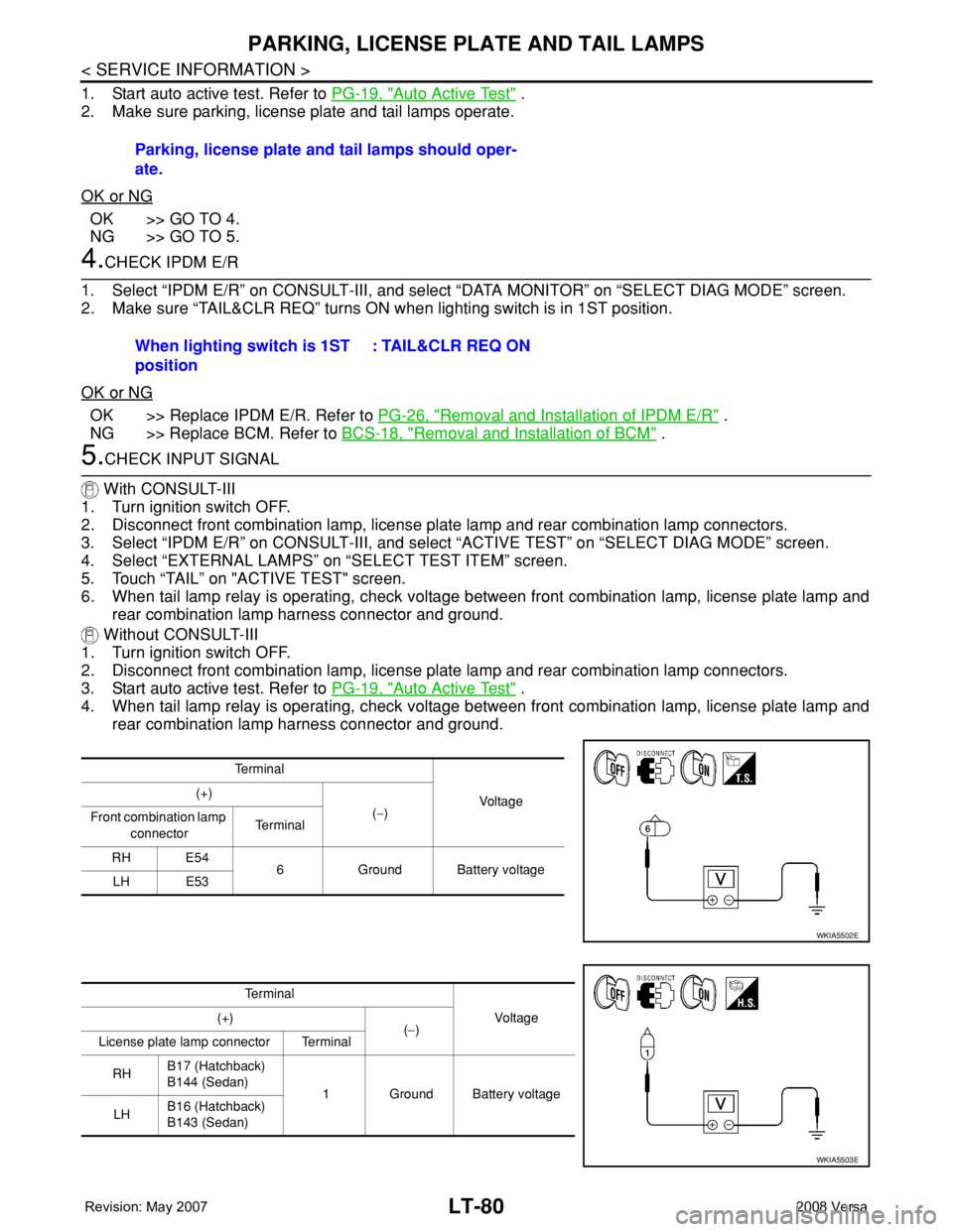
6. When tail lamp relay is operating, check voltage between front combination lamp, license plate lamp and
rear combination lamp harness connector and ground.
Without CONSULT-III
1. Turn ignition switch OFF.
2. Disconnect front combination lamp, license plate lamp and rear combination lamp connectors.
3. Start auto active test. Refer to PG-19, "
Auto Active Test" .
4. When tail lamp relay is operating, check voltage between front combination lamp, license plate lamp and
rear combination lamp harness connector and ground.Parking, license plate and tail lamps should oper-
ate.
When lighting switch is 1ST
position: TAIL&CLR REQ ON
Te r m i n a l
Voltag e (+)
(−)
Front combination lamp
connectorTe r m i n a l
RH E54
6 Ground Battery voltage
LH E53
WKIA5502E
Te r m i n a l
Vo l ta g e (+)
(−)
License plate lamp connector Terminal
RHB17 (Hatchback)
B144 (Sedan)
1 Ground Battery voltage
LHB16 (Hatchback)
B143 (Sedan)
WKIA5503E
Page 2218 of 2771
PARKING, LICENSE PLATE AND TAIL LAMPS
LT-81
< SERVICE INFORMATION >
C
D
E
F
G
H
I
J
L
MA
B
LT
N
O
P
OK or NG
OK >> GO TO 7.
NG >> GO TO 6.
6.CHECK PARKING, LICENSE PLATE AND TAIL LAMP CIRCUIT
1. Turn ignition switch OFF.
2. Disconnect IPDM E/R connector.
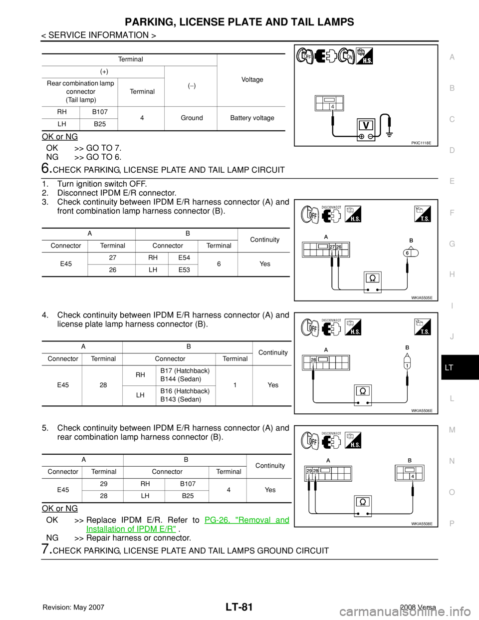
3. Check continuity between IPDM E/R harness connector (A) and
front combination lamp harness connector (B).
4. Check continuity between IPDM E/R harness connector (A) and
license plate lamp harness connector (B).
5. Check continuity between IPDM E/R harness connector (A) and
rear combination lamp harness connector (B).
OK or NG
OK >> Replace IPDM E/R. Refer to PG-26, "Removal and
Installation of IPDM E/R" .
NG >> Repair harness or connector.
7.CHECK PARKING, LICENSE PLATE AND TAIL LAMPS GROUND CIRCUIT
Te r m i n a l
Vo l ta g e (+)
(−) Rear combination lamp
connector
(Tail lamp)Te r m i n a l
RH B107
4 Ground Battery voltage
LH B25
P K I C 111 8 E
AB
Continuity
Connector Terminal Connector Terminal
E4527 RH E54
6Yes
26 LH E53
WKIA5505E
AB
Continuity
Connector Terminal Connector Terminal
E45 28RHB17 (Hatchback)
B144 (Sedan)
1Yes
LHB16 (Hatchback)
B143 (Sedan)
WKIA5506E
AB
Continuity
Connector Terminal Connector Terminal
E4529 RH B107
4Yes
28 LH B25
WKIA5508E
Page 2219 of 2771
LT-82
< SERVICE INFORMATION >
PARKING, LICENSE PLATE AND TAIL LAMPS
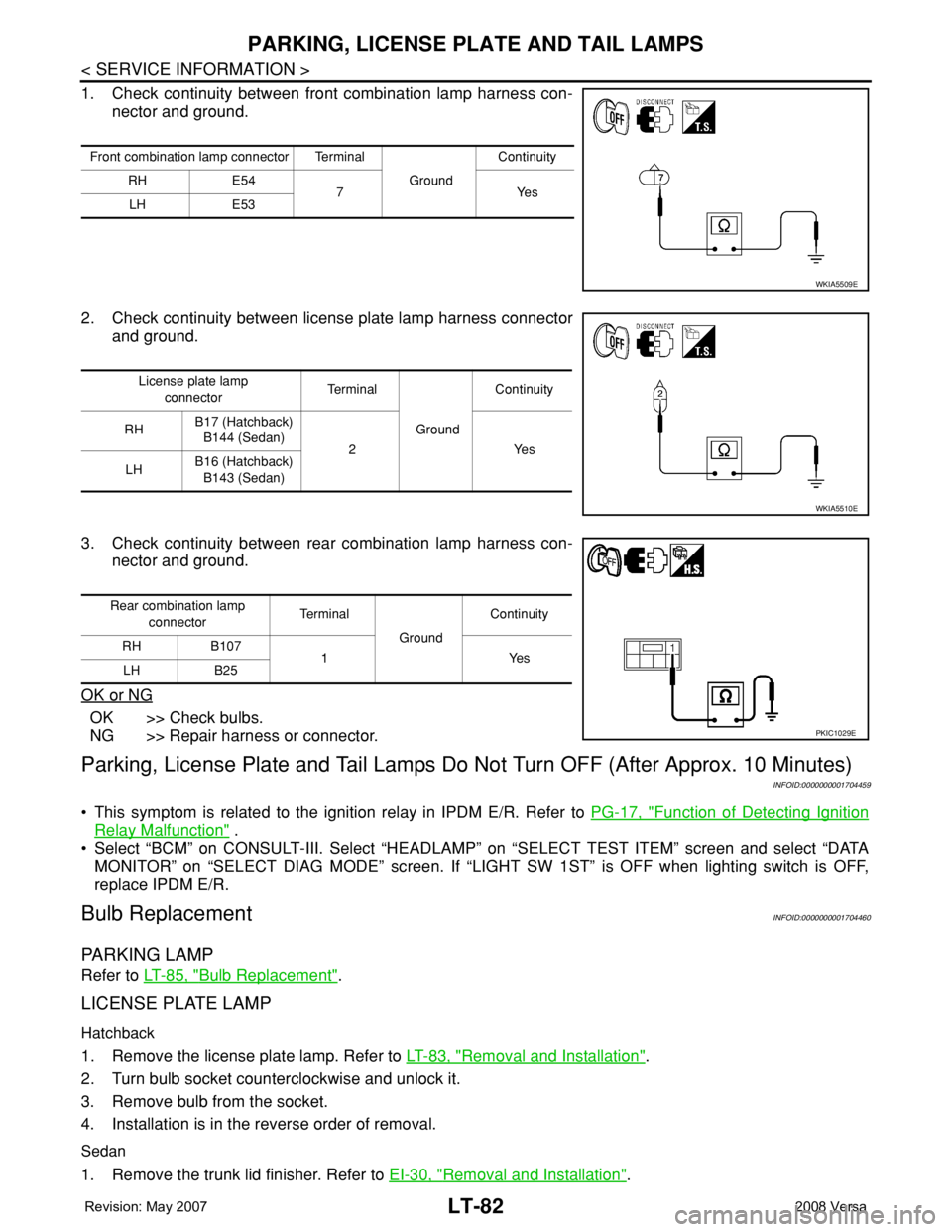
1. Check continuity between front combination lamp harness con-
nector and ground.
2. Check continuity between license plate lamp harness connector
and ground.
3. Check continuity between rear combination lamp harness con-
nector and ground.
OK or NG
OK >> Check bulbs.
NG >> Repair harness or connector.
Parking, License Plate and Tail Lamps Do Not Turn OFF (After Approx. 10 Minutes)
INFOID:0000000001704459
• This symptom is related to the ignition relay in IPDM E/R. Refer to PG-17, "Function of Detecting Ignition
Relay Malfunction" .
• Select “BCM” on CONSULT-III. Select “HEADLAMP” on “SELECT TEST ITEM” screen and select “DATA
MONITOR” on “SELECT DIAG MODE” screen. If “LIGHT SW 1ST” is OFF when lighting switch is OFF,
replace IPDM E/R.
Bulb ReplacementINFOID:0000000001704460
PARKING LAMP
Refer to LT-85, "Bulb Replacement".
LICENSE PLATE LAMP
Hatchback
1. Remove the license plate lamp. Refer to LT-83, "Removal and Installation".
2. Turn bulb socket counterclockwise and unlock it.
3. Remove bulb from the socket.
4. Installation is in the reverse order of removal.
Sedan
1. Remove the trunk lid finisher. Refer to EI-30, "Removal and Installation".
Front combination lamp connector Terminal
GroundContinuity
RH E54
7Yes
LH E53
WKIA5509E
License plate lamp
connectorTe r m i n a l
GroundContinuity
RHB17 (Hatchback)
B144 (Sedan)
2 Yes
LHB16 (Hatchback)
B143 (Sedan)
WKIA5510E
Rear combination lamp
connectorTe r m i n a l
GroundContinuity
RH B107
1Yes
LH B25
PKIC1029E
Page 2224 of 2771
INTERIOR LAMP
LT-87
< SERVICE INFORMATION >
C
D
E
F
G
H
I
J
L
MA
B
LT
N
O
P
INTERIOR LAMP
Map LampINFOID:0000000001704466
BULB REPLACEMENT
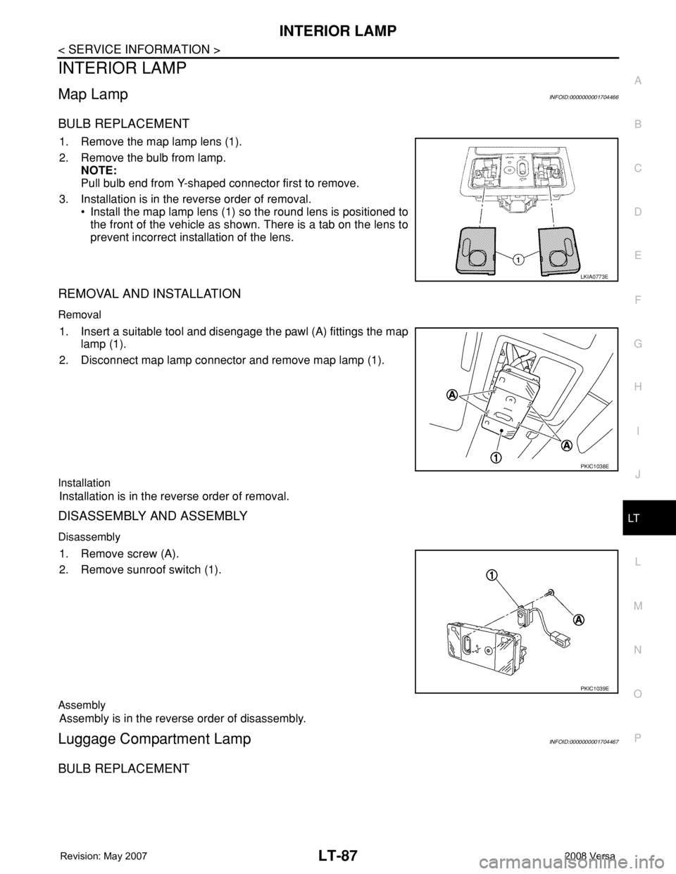
1. Remove the map lamp lens (1).
2. Remove the bulb from lamp.
NOTE:
Pull bulb end from Y-shaped connector first to remove.
3. Installation is in the reverse order of removal.
• Install the map lamp lens (1) so the round lens is positioned to
the front of the vehicle as shown. There is a tab on the lens to
prevent incorrect installation of the lens.
REMOVAL AND INSTALLATION
Removal
1. Insert a suitable tool and disengage the pawl (A) fittings the map
lamp (1).
2. Disconnect map lamp connector and remove map lamp (1).
Installation
Installation is in the reverse order of removal.
DISASSEMBLY AND ASSEMBLY
Disassembly
1. Remove screw (A).
2. Remove sunroof switch (1).
Assembly
Assembly is in the reverse order of disassembly.
Luggage Compartment LampINFOID:0000000001704467
BULB REPLACEMENT
LKIA0773E
PKIC1038E
PKIC1039E
Page 2226 of 2771
INTERIOR ROOM LAMP
LT-89
< SERVICE INFORMATION >
C
D
E
F
G
H
I
J
L
MA
B
LT
N
O
P
INTERIOR ROOM LAMP
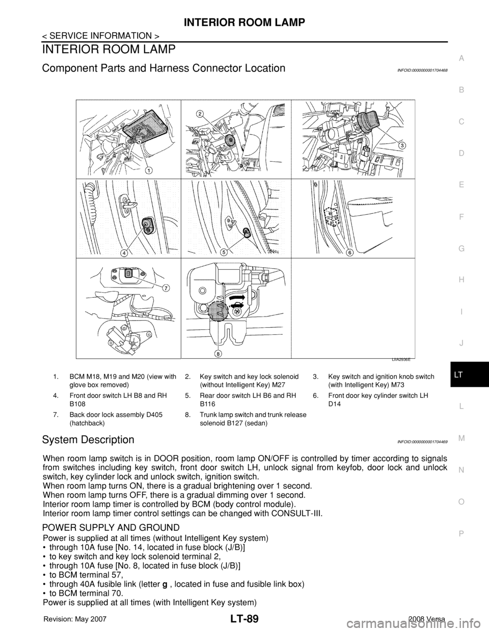
Component Parts and Harness Connector LocationINFOID:0000000001704468
System DescriptionINFOID:0000000001704469
When room lamp switch is in DOOR position, room lamp ON/OFF is controlled by timer according to signals
from switches including key switch, front door switch LH, unlock signal from keyfob, door lock and unlock
switch, key cylinder lock and unlock switch, ignition switch.
When room lamp turns ON, there is a gradual brightening over 1 second.
When room lamp turns OFF, there is a gradual dimming over 1 second.
Interior room lamp timer is controlled by BCM (body control module).
Interior room lamp timer control settings can be changed with CONSULT-III.
POWER SUPPLY AND GROUND
Power is supplied at all times (without Intelligent Key system)
• through 10A fuse [No. 14, located in fuse block (J/B)]
• to key switch and key lock solenoid terminal 2,
• through 10A fuse [No. 8, located in fuse block (J/B)]
• to BCM terminal 57,
• through 40A fusible link (letter g , located in fuse and fusible link box)
• to BCM terminal 70.
Power is supplied at all times (with Intelligent Key system)
1. BCM M18, M19 and M20 (view with
glove box removed)2. Key switch and key lock solenoid
(without Intelligent Key) M273. Key switch and ignition knob switch
(with Intelligent Key) M73
4. Front door switch LH B8 and RH
B1085. Rear door switch LH B6 and RH
B1166. Front door key cylinder switch LH
D14
7. Back door lock assembly D405
(hatchback)8. Trunk lamp switch and trunk release
solenoid B127 (sedan)
LIIA2936E
Page 2227 of 2771

LT-90
< SERVICE INFORMATION >
INTERIOR ROOM LAMP
• through 10A fuse (No. 31, located in fuse and fusible link box)
• to key switch and ignition knob switch terminals 2 and 4,
• through 10A fuse [No. 8, located in fuse block (J/B)]
• to BCM terminal 57,
• through 40A fusible link (letter g , located in fuse and fusible link box)
• to BCM terminal 70.
When key is inserted in the key switch and key lock solenoid, power is supplied (without Intelligent Key sys-
tem)
• through key switch and key lock solenoid terminal 1
• to BCM terminal 37.
When key is inserted in the key switch and ignition knob switch, power is supplied (with Intelligent Key system)
• through key switch and ignition knob switch terminal 1
• to BCM terminal 37.
When ignition knob switch is pushed, power is supplied (with Intelligent Key system)
• through key switch and ignition knob switch terminal 3
• to Intelligent Key unit terminal 27.
With the ignition switch in the ON or START position, power is supplied
• through 10A fuse [No. 6, located in fuse block (J/B)]
• to BCM terminal 38.
Ground is supplied
• to BCM terminal 67
• through grounds M57 and M61.
When front door LH is opened, ground is supplied
• to BCM terminal 47
• through front door switch LH terminal 2
• through case ground of front door switch LH.
When front door RH is opened, ground is supplied
• to BCM terminal 12
• through front door switch RH terminal 2
• through case ground of front door switch RH.
When rear door LH is opened, ground is supplied
• to BCM terminal 48
• through rear door switch LH terminal 1
• through case ground of rear door switch LH.
When rear door RH is opened, ground is supplied
• to BCM terminal 13
• through rear door switch RH terminal 1
• through case ground of rear door switch RH.
When back door (hatchback) is opened, ground is supplied
• to BCM terminal 43
• through back door lock assembly (back door switch) terminal 3
• through back door lock assembly (back door switch) terminal 4
• through grounds B117, B132 and D402.
When trunk lid (sedan) is opened, ground is supplied
• to BCM terminal 42
• through trunk lamp switch and trunk release solenoid terminal 3
• through trunk lamp switch and trunk release solenoid terminal 1
• through grounds B117 and B132.
When front door LH is unlocked by front door key cylinder switch LH, the BCM receives a ground signal
• to BCM terminal 7
• through front door key cylinder switch LH terminal 3
• through front door key cylinder switch LH terminal 2
• through grounds M57 and M61.
When a signal, or combination of signals is received by BCM, ground is supplied
• to room lamp terminal 2
• through map lamp terminals 5 and 2 (with map lamp)
• through BCM terminal 63.
With power and ground supplied, the interior room lamp illuminates.
SWITCH OPERATION
When map lamp switch is ON (with map lamp), ground is supplied
• through grounds M57 and M61.