2008 NISSAN TIIDA PN switch
[x] Cancel search: PN switchPage 2306 of 2771
MT-18
< SERVICE INFORMATION >
TRANSAXLE ASSEMBLY
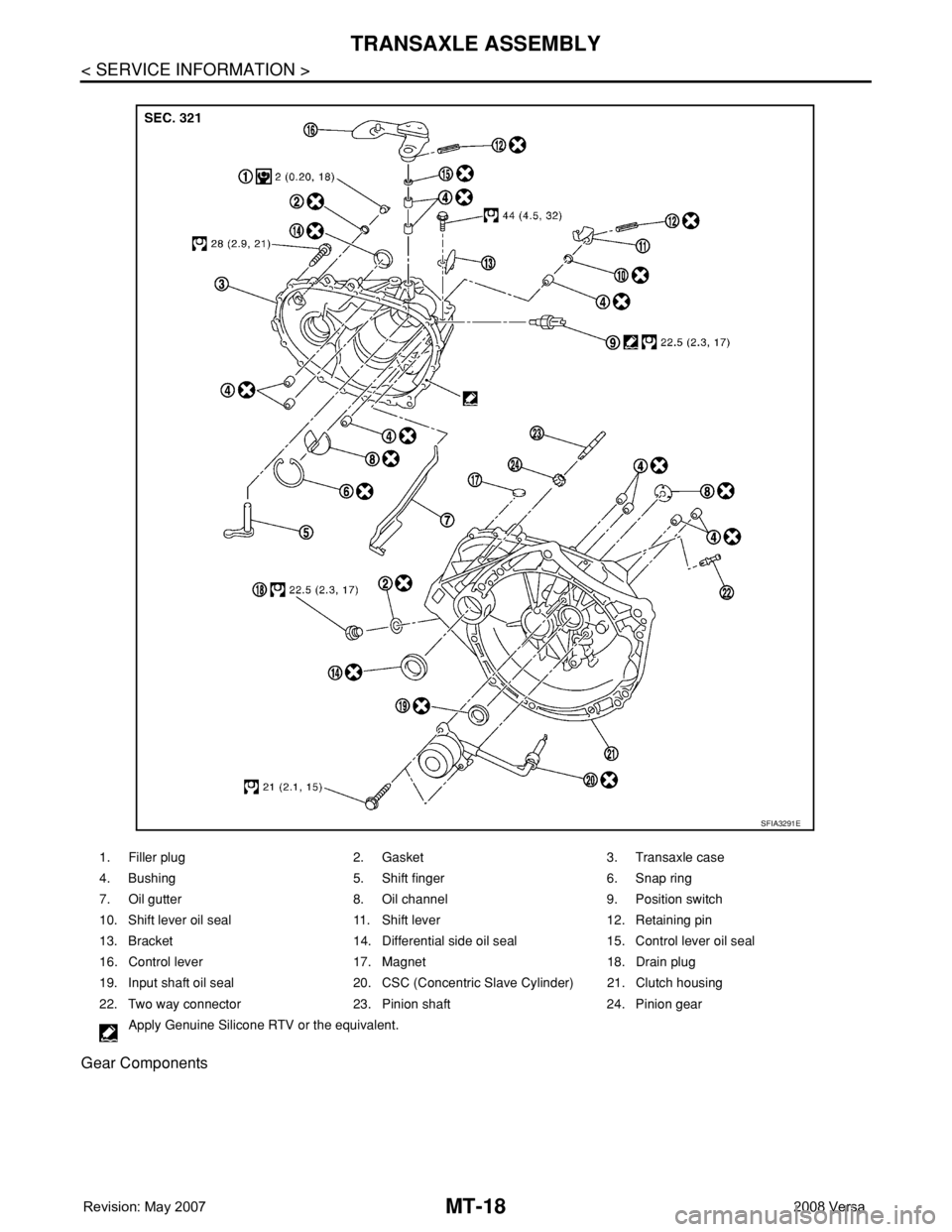
Gear Components
1. Filler plug 2. Gasket 3. Transaxle case
4. Bushing 5. Shift finger 6. Snap ring
7. Oil gutter 8. Oil channel 9. Position switch
10. Shift lever oil seal 11. Shift lever 12. Retaining pin
13. Bracket 14. Differential side oil seal 15. Control lever oil seal
16. Control lever 17. Magnet 18. Drain plug
19. Input shaft oil seal 20. CSC (Concentric Slave Cylinder) 21. Clutch housing
22. Two way connector 23. Pinion shaft 24. Pinion gear
Apply Genuine Silicone RTV or the equivalent.
SFIA3291E
Page 2311 of 2771
TRANSAXLE ASSEMBLY
MT-23
< SERVICE INFORMATION >
D
E
F
G
H
I
J
K
L
MA
B
MT
N
O
P
DISASSEMBLY
1. Remove drain plug and gasket from clutch housing, and drain oil.
2. Remove filler plug and gasket from transaxle case.
3. Remove CSC from clutch housing.
4. Remove retaining pin from shift lever (1) using suitable tool.
5. Remove bracket (2) and position switch (3) from transaxle case.
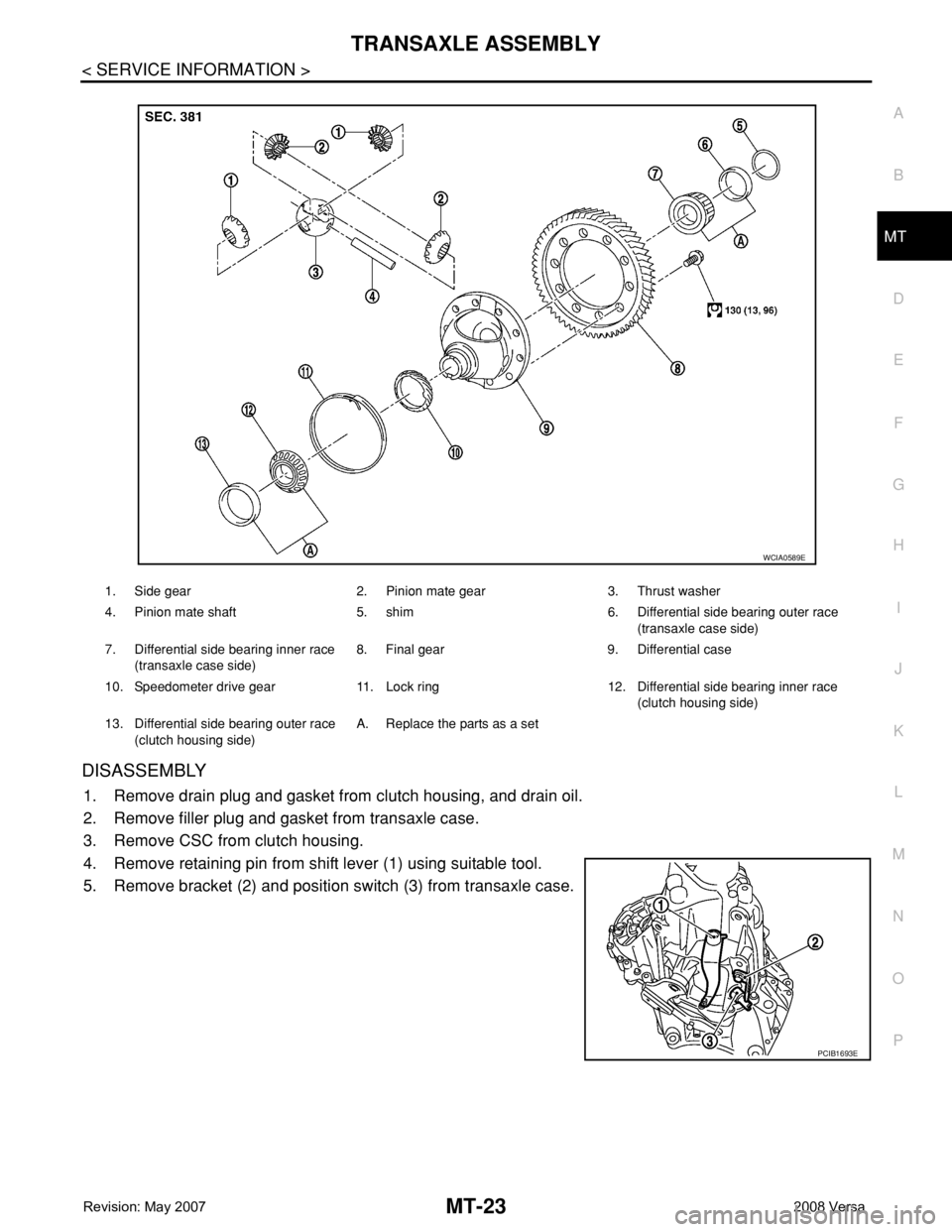
1. Side gear 2. Pinion mate gear 3. Thrust washer
4. Pinion mate shaft 5. shim 6. Differential side bearing outer race
(transaxle case side)
7. Differential side bearing inner race
(transaxle case side)8. Final gear 9. Differential case
10. Speedometer drive gear 11. Lock ring 12. Differential side bearing inner race
(clutch housing side)
13. Differential side bearing outer race
(clutch housing side)A. Replace the parts as a set
WCIA0589E
PCIB1693E
Page 2322 of 2771
MT-34
< SERVICE INFORMATION >
TRANSAXLE ASSEMBLY
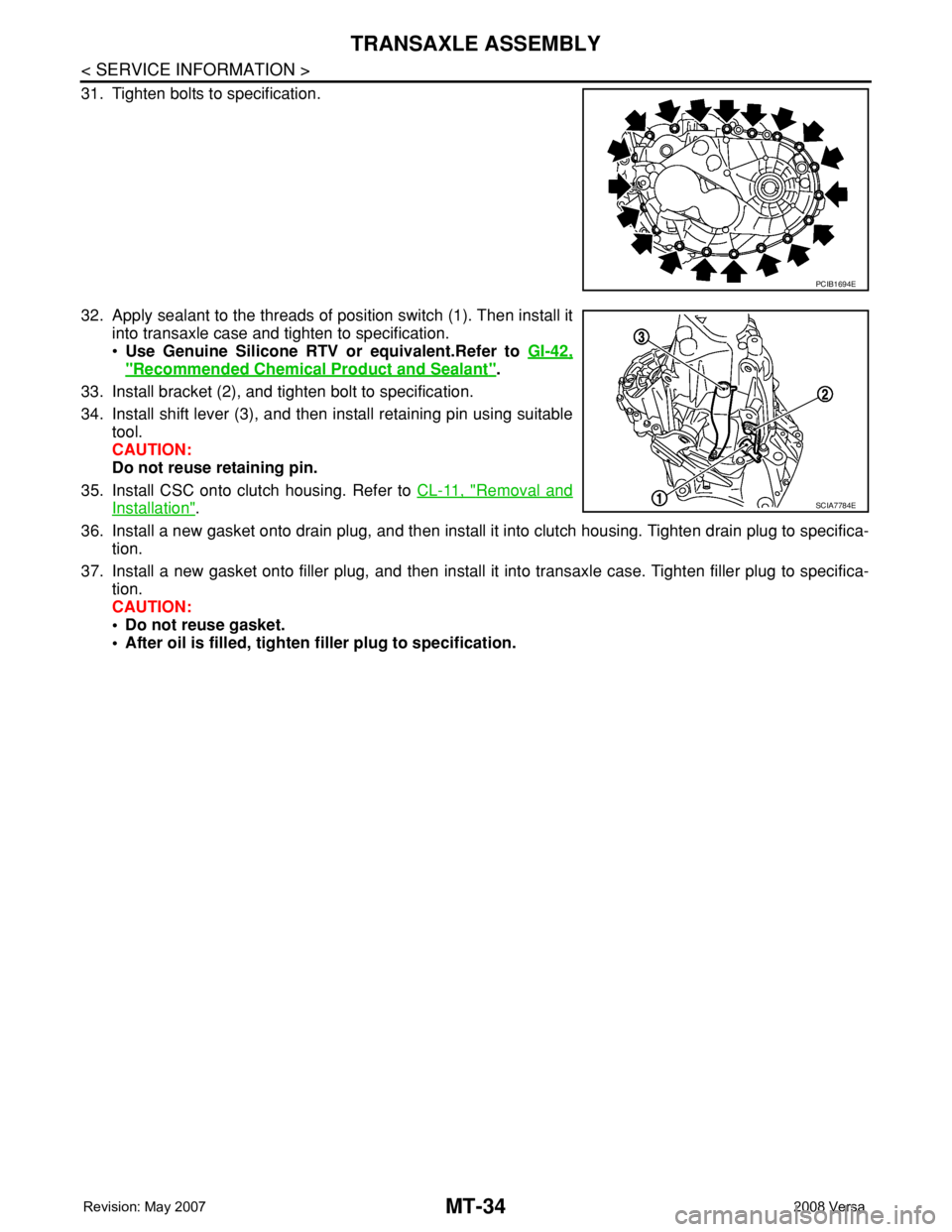
31. Tighten bolts to specification.
32. Apply sealant to the threads of position switch (1). Then install it
into transaxle case and tighten to specification.
•Use Genuine Silicone RTV or equivalent.Refer to GI-42,
"Recommended Chemical Product and Sealant".
33. Install bracket (2), and tighten bolt to specification.
34. Install shift lever (3), and then install retaining pin using suitable
tool.
CAUTION:
Do not reuse retaining pin.
35. Install CSC onto clutch housing. Refer to CL-11, "
Removal and
Installation".
36. Install a new gasket onto drain plug, and then install it into clutch housing. Tighten drain plug to specifica-
tion.
37. Install a new gasket onto filler plug, and then install it into transaxle case. Tighten filler plug to specifica-
tion.
CAUTION:
• Do not reuse gasket.
• After oil is filled, tighten filler plug to specification.
PCIB1694E
SCIA7784E
Page 2341 of 2771
PRECAUTIONS
MTC-3
< SERVICE INFORMATION >
C
D
E
F
G
H
I
K
L
MA
B
MTC
N
O
P
SERVICE INFORMATION
PRECAUTIONS
Precaution for Supplemental Restraint System (SRS) "AIR BAG" and "SEAT BELT
PRE-TENSIONER"
INFOID:0000000001704274
The Supplemental Restraint System such as “AIR BAG” and “SEAT BELT PRE-TENSIONER”, used along
with a front seat belt, helps to reduce the risk or severity of injury to the driver and front passenger for certain
types of collision. This system includes seat belt switch inputs and dual stage front air bag modules. The SRS
system uses the seat belt switches to determine the front air bag deployment, and may only deploy one front
air bag, depending on the severity of a collision and whether the front occupants are belted or unbelted.
Information necessary to service the system safely is included in the SRS and SB section of this Service Man-
ual.
WARNING:
• To avoid rendering the SRS inoperative, which could increase the risk of personal injury or death in
the event of a collision which would result in air bag inflation, all maintenance must be performed by
an authorized NISSAN/INFINITI dealer.
• Improper maintenance, including incorrect removal and installation of the SRS, can lead to personal
injury caused by unintentional activation of the system. For removal of Spiral Cable and Air Bag
Module, see the SRS section.
• Do not use electrical test equipment on any circuit related to the SRS unless instructed to in this
Service Manual. SRS wiring harnesses can be identified by yellow and/or orange harnesses or har-
ness connectors.
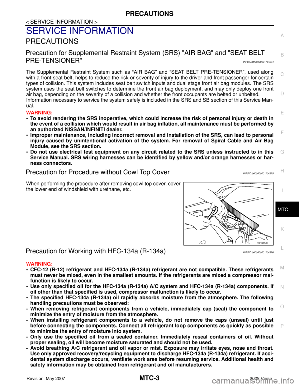
Precaution for Procedure without Cowl Top CoverINFOID:0000000001704275
When performing the procedure after removing cowl top cover, cover
the lower end of windshield with urethane, etc.
Precaution for Working with HFC-134a (R-134a)INFOID:0000000001704276
WARNING:
• CFC-12 (R-12) refrigerant and HFC-134a (R-134a) refrigerant are not compatible. These refrigerants
must never be mixed, even in the smallest amounts. If the refrigerants are mixed a compressor mal-
function is likely to occur.
• Use only specified oil for the HFC-134a (R-134a) A/C system and HFC-134a (R-134a) components. If
oil other than that specified is used, compressor malfunction is likely to occur.
• The specified HFC-134a (R-134a) oil rapidly absorbs moisture from the atmosphere. The following
handling precautions must be observed:
- When removing refrigerant components from a vehicle, immediately cap (seal) the component to
minimize the entry of moisture from the atmosphere.
- When installing refrigerant components to a vehicle, do not remove the caps (unseal) until just
before connecting the components. Connect all refrigerant loop components as quickly as possible
to minimize the entry of moisture into system.
- Only use the specified oil from a sealed container. Immediately reseal containers of oil. Without
proper sealing, oil will become moisture saturated and should not be used.
- Avoid breathing A/C refrigerant and oil vapor or mist. Exposure may irritate eyes, nose and throat.
Use only approved recovery/recycling equipment to discharge HFC-134a (R-134a) refrigerant. If acci-
dental system discharge occurs, ventilate work area before resuming service. Additional health and
safety information may be obtained from refrigerant and oil manufacturers.
PIIB3706J
Page 2346 of 2771
MTC-8
< SERVICE INFORMATION >
PRECAUTIONS
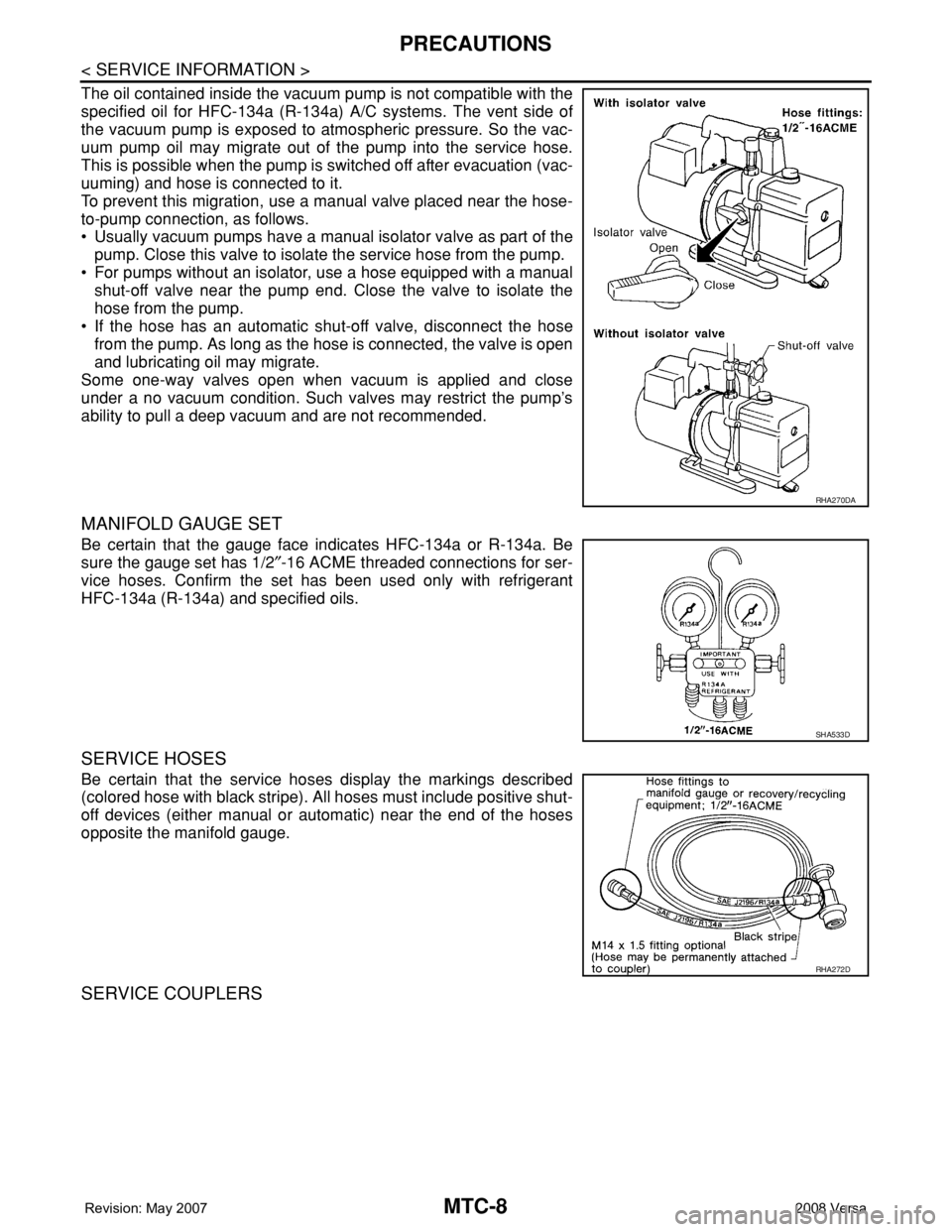
The oil contained inside the vacuum pump is not compatible with the
specified oil for HFC-134a (R-134a) A/C systems. The vent side of
the vacuum pump is exposed to atmospheric pressure. So the vac-
uum pump oil may migrate out of the pump into the service hose.
This is possible when the pump is switched off after evacuation (vac-
uuming) and hose is connected to it.
To prevent this migration, use a manual valve placed near the hose-
to-pump connection, as follows.
• Usually vacuum pumps have a manual isolator valve as part of the
pump. Close this valve to isolate the service hose from the pump.
• For pumps without an isolator, use a hose equipped with a manual
shut-off valve near the pump end. Close the valve to isolate the
hose from the pump.
• If the hose has an automatic shut-off valve, disconnect the hose
from the pump. As long as the hose is connected, the valve is open
and lubricating oil may migrate.
Some one-way valves open when vacuum is applied and close
under a no vacuum condition. Such valves may restrict the pump’s
ability to pull a deep vacuum and are not recommended.
MANIFOLD GAUGE SET
Be certain that the gauge face indicates HFC-134a or R-134a. Be
sure the gauge set has 1/2″-16 ACME threaded connections for ser-
vice hoses. Confirm the set has been used only with refrigerant
HFC-134a (R-134a) and specified oils.
SERVICE HOSES
Be certain that the service hoses display the markings described
(colored hose with black stripe). All hoses must include positive shut-
off devices (either manual or automatic) near the end of the hoses
opposite the manifold gauge.
SERVICE COUPLERS
RHA270DA
SHA533D
RHA272D
Page 2352 of 2771
MTC-14
< SERVICE INFORMATION >
REFRIGERATION SYSTEM
REFRIGERATION SYSTEM
Refrigerant CycleINFOID:0000000001704286
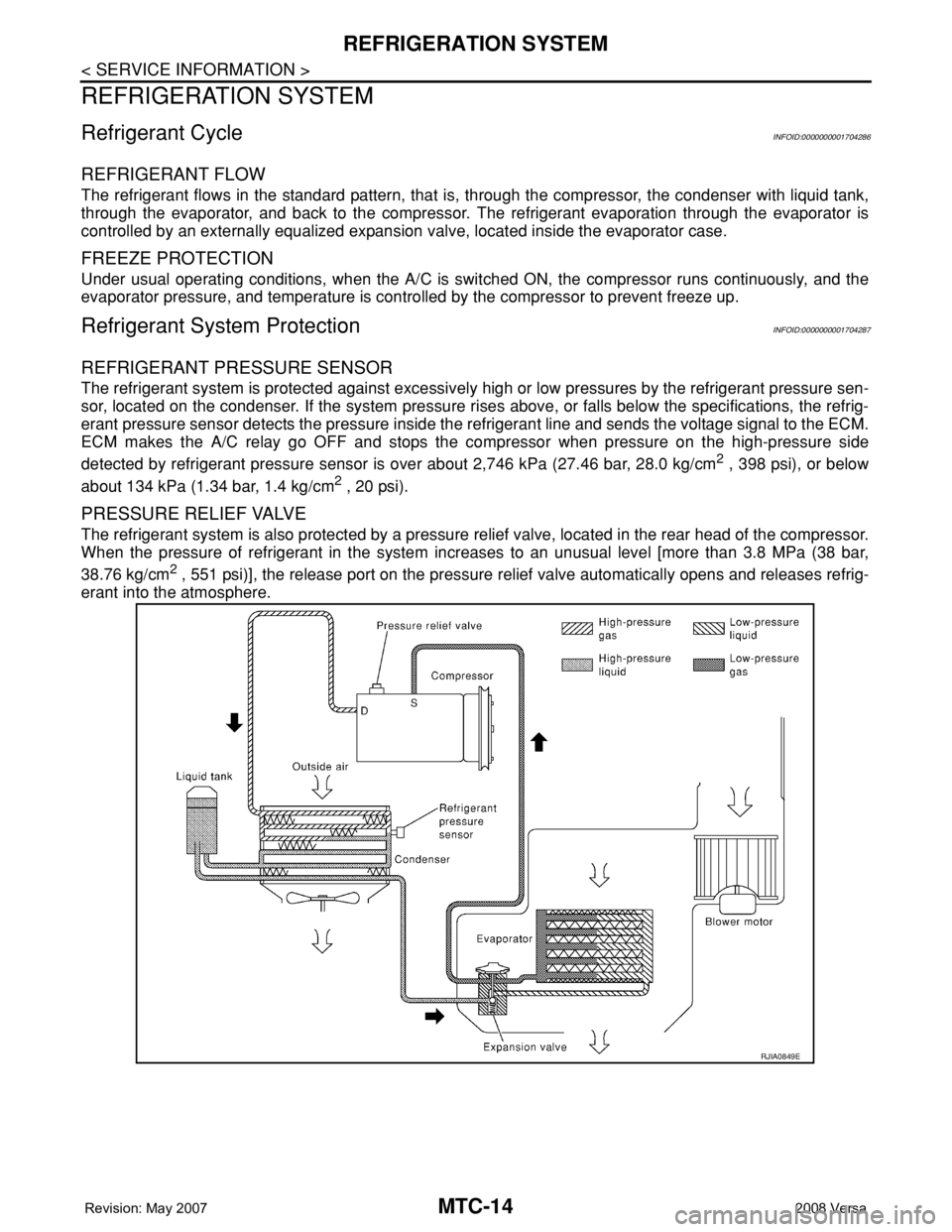
REFRIGERANT FLOW
The refrigerant flows in the standard pattern, that is, through the compressor, the condenser with liquid tank,
through the evaporator, and back to the compressor. The refrigerant evaporation through the evaporator is
controlled by an externally equalized expansion valve, located inside the evaporator case.
FREEZE PROTECTION
Under usual operating conditions, when the A/C is switched ON, the compressor runs continuously, and the
evaporator pressure, and temperature is controlled by the compressor to prevent freeze up.
Refrigerant System ProtectionINFOID:0000000001704287
REFRIGERANT PRESSURE SENSOR
The refrigerant system is protected against excessively high or low pressures by the refrigerant pressure sen-
sor, located on the condenser. If the system pressure rises above, or falls below the specifications, the refrig-
erant pressure sensor detects the pressure inside the refrigerant line and sends the voltage signal to the ECM.
ECM makes the A/C relay go OFF and stops the compressor when pressure on the high-pressure side
detected by refrigerant pressure sensor is over about 2,746 kPa (27.46 bar, 28.0 kg/cm
2 , 398 psi), or below
about 134 kPa (1.34 bar, 1.4 kg/cm
2 , 20 psi).
PRESSURE RELIEF VALVE
The refrigerant system is also protected by a pressure relief valve, located in the rear head of the compressor.
When the pressure of refrigerant in the system increases to an unusual level [more than 3.8 MPa (38 bar,
38.76 kg/cm
2 , 551 psi)], the release port on the pressure relief valve automatically opens and releases refrig-
erant into the atmosphere.
RJIA0849E
Page 2354 of 2771
MTC-16
< SERVICE INFORMATION >
OIL
OIL
Maintenance of Oil Quantity in CompressorINFOID:0000000001704289
The oil in the compressor circulates through the system with the refrigerant. Add oil to compressor when
replacing any component or after a large refrigerant leakage occurred. It is important to maintain the specified
amount.
If oil quantity is not maintained properly, the following malfunctions may result:
• Lack of oil: May lead to a seized compressor.
• Excessive oil: Inadequate cooling (thermal exchange interference)
OIL
OIL RETURN OPERATION
Adjust the oil quantity according to the test group shown below.
1.CHECK OIL RETURN OPERATION
Can oil return operation be performed?
• A/C system works properly.
• There is no evidence of a large amount of oil leakage.
CAUTION:
If excessive oil leakage is noted, do not perform the oil return operation.
OK or NG
OK >> GO TO 2.
NG >> GO TO 3.
2.PERFORM OIL RETURN OPERATION, PROCEEDING AS FOLLOWS
1. Start engine, and set the following conditions:
- Engine speed: Idling to 1,200 rpm
- A/C blower switch: ON
- Blower speed: Max. position
- Temp. control: Optional [Set so that intake air temperature is 25° to 30°C (77° to 86° F)].
- Intake position: Recirculation (REC)
2. Perform oil return operation for about 10 minutes.
3. Stop engine.
>> GO TO 3.
3.CHECK REPLACEMENT PART
Should the compressor be replaced?
YES >> GO TO "OIL ADJUSTING PROCEDURE FOR COMPRESSOR REPLACEMENT".
NO >> GO TO "OIL ADJUSTING PROCEDURE FOR COMPONENTS REPLACEMENT EXCEPT COM-
PRESSOR".
OIL ADJUSTING PROCEDURE FOR COMPONENTS REPLACEMENT EXCEPT COMPRESSOR
After replacing any of the following major components, add the correct amount of oil to the system.
Amount Of Oil To Be Added
TYPE 1 Compressor (CR-10) : NISSAN A/C System Oil Type R
TYPE 2 Compressor (CSV511) : NISSAN A/C System Oil Type S
Part replacedOil to be added to system
Remarks
Amount of oil
m (US fl oz, Imp fl oz)
Evaporator 35 (1.2, 1.2) -
Condenser 15 (0.5, 0.5) -
Liquid tank 5 (0.2, 0.2) -
Page 2357 of 2771
AIR CONDITIONER CONTROL
MTC-19
< SERVICE INFORMATION >
C
D
E
F
G
H
I
K
L
MA
B
MTC
N
O
P
AIR CONDITIONER CONTROL
Control OperationINFOID:0000000001704290
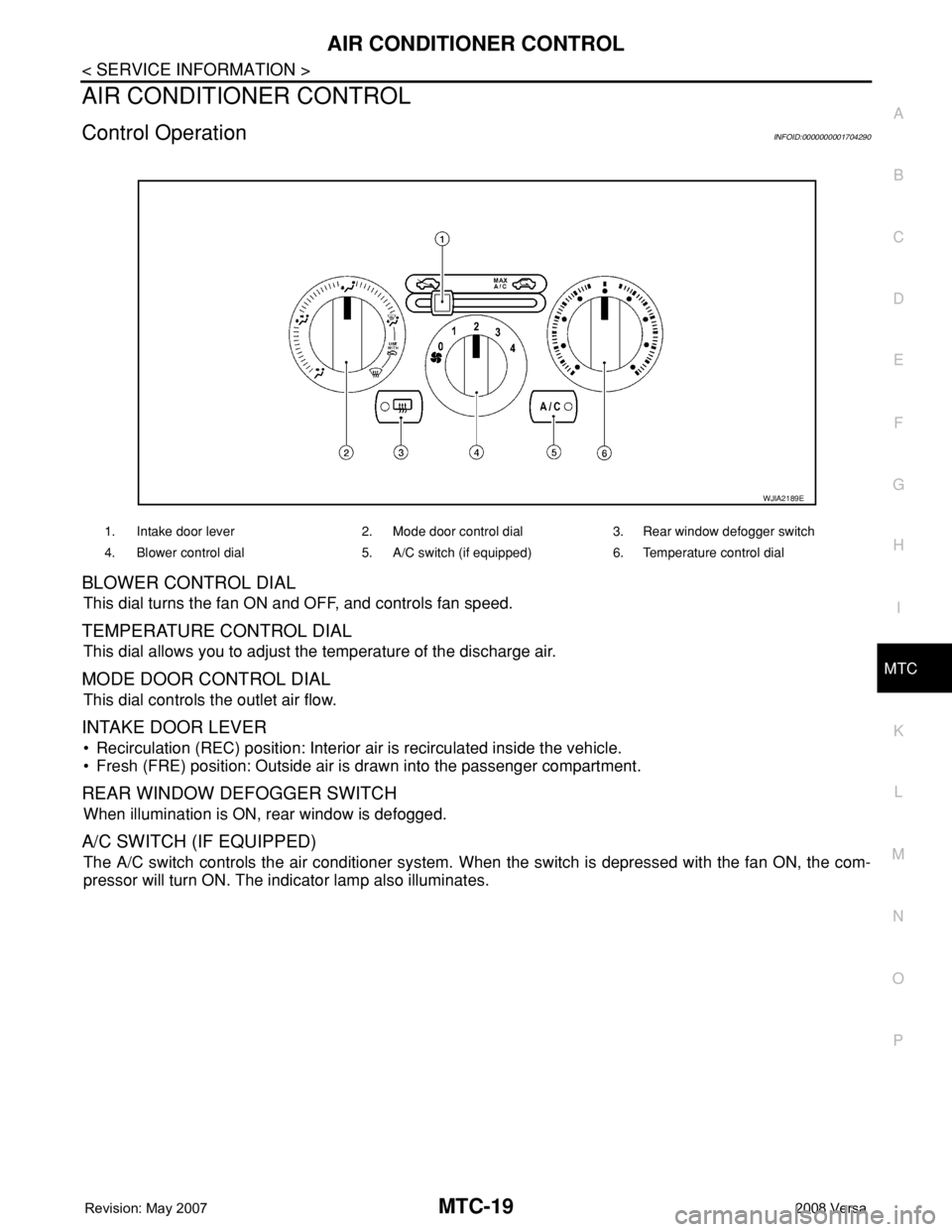
BLOWER CONTROL DIAL
This dial turns the fan ON and OFF, and controls fan speed.
TEMPERATURE CONTROL DIAL
This dial allows you to adjust the temperature of the discharge air.
MODE DOOR CONTROL DIAL
This dial controls the outlet air flow.
INTAKE DOOR LEVER
• Recirculation (REC) position: Interior air is recirculated inside the vehicle.
• Fresh (FRE) position: Outside air is drawn into the passenger compartment.
REAR WINDOW DEFOGGER SWITCH
When illumination is ON, rear window is defogged.
A/C SWITCH (IF EQUIPPED)
The A/C switch controls the air conditioner system. When the switch is depressed with the fan ON, the com-
pressor will turn ON. The indicator lamp also illuminates.
1. Intake door lever 2. Mode door control dial 3. Rear window defogger switch
4. Blower control dial 5. A/C switch (if equipped) 6. Temperature control dial
WJIA2189E