2008 NISSAN TEANA engine
[x] Cancel search: enginePage 1994 of 5121
CYLINDER BLOCK
EM-119
< DISASSEMBLY AND ASSEMBLY >
C
D
E
F
G
H
I
J
K
L
MA
EM
N
P O
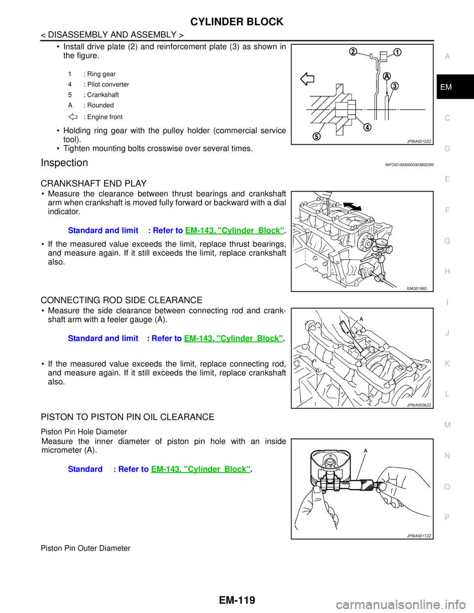
Install drive plate (2) and reinforcement plate (3) as shown in
the figure.
Holding ring gear with the pulley holder (commercial service
tool).
Tighten mounting bolts crosswise over several times.
InspectionINFOID:0000000003802295
CRANKSHAFT END PLAY
Measure the clearance between thrust bearings and crankshaft
arm when crankshaft is moved fully forward or backward with a dial
indicator.
If the measured value exceeds the limit, replace thrust bearings,
and measure again. If it still exceeds the limit, replace crankshaft
also.
CONNECTING ROD SIDE CLEARANCE
Measure the side clearance between connecting rod and crank-
shaft arm with a feeler gauge (A).
If the measured value exceeds the limit, replace connecting rod,
and measure again. If it still exceeds the limit, replace crankshaft
also.
PISTON TO PISTON PIN OIL CLEARANCE
Piston Pin Hole Diameter
Measure the inner diameter of piston pin hole with an inside
micrometer (A).
Piston Pin Outer Diameter
1 : Ring gear
4 : Pilot converter
5 : Crankshaft
A : Rounded
: Engine front
JPBIA0212ZZ
Standard and limit : Refer to EM-143, "CylinderBlock".
EMQ0196D
Standard and limit : Refer to EM-143, "CylinderBlock".
JPBIA0536ZZ
Standard : Refer to EM-143, "CylinderBlock".
JPBIA0217ZZ
Page 1995 of 5121
EM-120
< DISASSEMBLY AND ASSEMBLY >
CYLINDER BLOCK
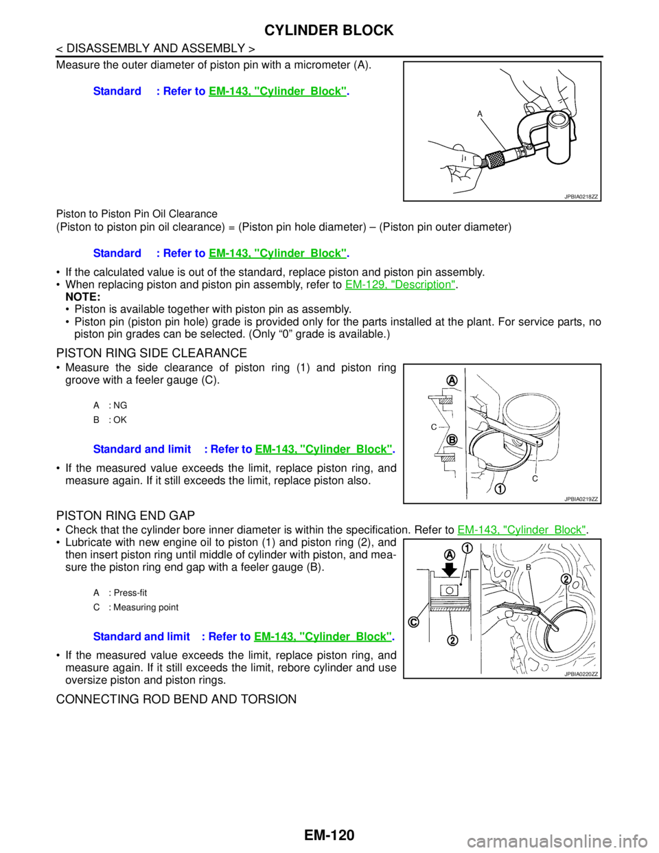
Measure the outer diameter of piston pin with a micrometer (A).
Piston to Piston Pin Oil Clearance
(Piston to piston pin oil clearance) = (Piston pin hole diameter) – (Piston pin outer diameter)
If the calculated value is out of the standard, replace piston and piston pin assembly.
When replacing piston and piston pin assembly, refer to EM-129, "
Description".
NOTE:
Piston is available together with piston pin as assembly.
Piston pin (piston pin hole) grade is provided only for the parts installed at the plant. For service parts, no
piston pin grades can be selected. (Only “0” grade is available.)
PISTON RING SIDE CLEARANCE
Measure the side clearance of piston ring (1) and piston ring
groove with a feeler gauge (C).
If the measured value exceeds the limit, replace piston ring, and
measure again. If it still exceeds the limit, replace piston also.
PISTON RING END GAP
Check that the cylinder bore inner diameter is within the specification. Refer to EM-143, "CylinderBlock".
Lubricate with new engine oil to piston (1) and piston ring (2), and
then insert piston ring until middle of cylinder with piston, and mea-
sure the piston ring end gap with a feeler gauge (B).
If the measured value exceeds the limit, replace piston ring, and
measure again. If it still exceeds the limit, rebore cylinder and use
oversize piston and piston rings.
CONNECTING ROD BEND AND TORSION
Standard : Refer to EM-143, "CylinderBlock".
JPBIA0218ZZ
Standard : Refer to EM-143, "CylinderBlock".
A: NG
B: OK
Standard and limit : Refer to EM-143, "CylinderBlock".
JPBIA0219ZZ
A : Press-fit
C : Measuring point
Standard and limit : Refer to EM-143, "CylinderBlock".
JPBIA0220ZZ
Page 1998 of 5121
CYLINDER BLOCK
EM-123
< DISASSEMBLY AND ASSEMBLY >
C
D
E
F
G
H
I
J
K
L
MA
EM
N
P O
Unit: mm (in)
*: After installing in connecting rod
CYLINDER BLOCK DISTORTION
Using a scraper, remove gasket on the cylinder block surface, and also remove engine oil, scale, carbon, or
other contamination.
CAUTION:
Be careful not to allow gasket flakes to enter engine oil or engine coolant passages.
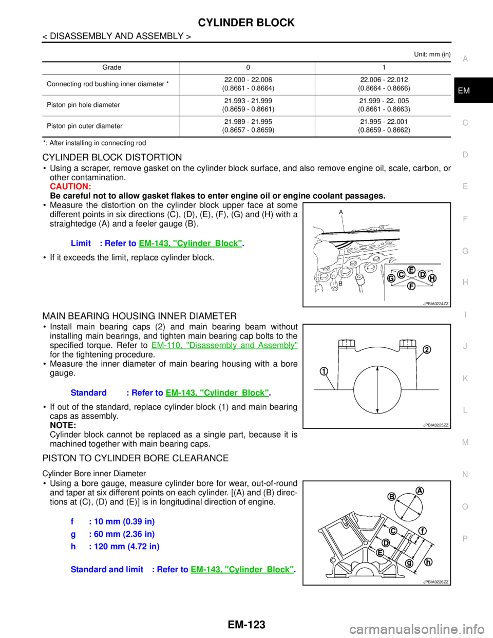
Measure the distortion on the cylinder block upper face at some
different points in six directions (C), (D), (E), (F), (G) and (H) with a
straightedge (A) and a feeler gauge (B).
If it exceeds the limit, replace cylinder block.
MAIN BEARING HOUSING INNER DIAMETER
Install main bearing caps (2) and main bearing beam without
installing main bearings, and tighten main bearing cap bolts to the
specified torque. Refer to EM-110, "
Disassembly and Assembly"
for the tightening procedure.
Measure the inner diameter of main bearing housing with a bore
gauge.
If out of the standard, replace cylinder block (1) and main bearing
caps as assembly.
NOTE:
Cylinder block cannot be replaced as a single part, because it is
machined together with main bearing caps.
PISTON TO CYLINDER BORE CLEARANCE
Cylinder Bore inner Diameter
Using a bore gauge, measure cylinder bore for wear, out-of-round
and taper at six different points on each cylinder. [(A) and (B) direc-
tions at (C), (D) and (E)] is in longitudinal direction of engine.
Grade 0 1
Connecting rod bushing inner diameter *22.000 - 22.006
(0.8661 - 0.8664)22.006 - 22.012
(0.8664 - 0.8666)
Piston pin hole diameter21.993 - 21.999
(0.8659 - 0.8661)21.999 - 22. 005
(0.8661 - 0.8663)
Piston pin outer diameter21.989 - 21.995
(0.8657 - 0.8659)21.995 - 22.001
(0.8659 - 0.8662)
Limit : Refer to EM-143, "CylinderBlock".
JPBIA0224ZZ
Standard : Refer to EM-143, "CylinderBlock".
JPBIA0225ZZ
f : 10 mm (0.39 in)
g : 60 mm (2.36 in)
h : 120 mm (4.72 in)
Standard and limit : Refer to EM-143, "
CylinderBlock".
JPBIA0226ZZ
Page 2001 of 5121
EM-126
< DISASSEMBLY AND ASSEMBLY >
CYLINDER BLOCK
If the calculated value exceeds the limit, select proper connecting rod bearing according to connecting rod
big end diameter and crankshaft pin journal diameter to obtain the specified bearing oil clearance. Refer to
EM-130, "
ConnectingRodBearing".
Method of Using Plastigage
Remove oil and dust on crankshaft pin journal and the surfaces of each bearing completely.
Cut a plastigage slightly shorter than the bearing width, and place it in crankshaft axial direction, avoiding oil
holes.
Install connecting rod bearings to connecting rod and connecting rod bearing cap, and tighten connecting
rod bolts to the specified torque. Refer to EM-110, "
Disassembly and Assembly" for the tightening proce-
dure.
CAUTION:
Never rotate crankshaft.
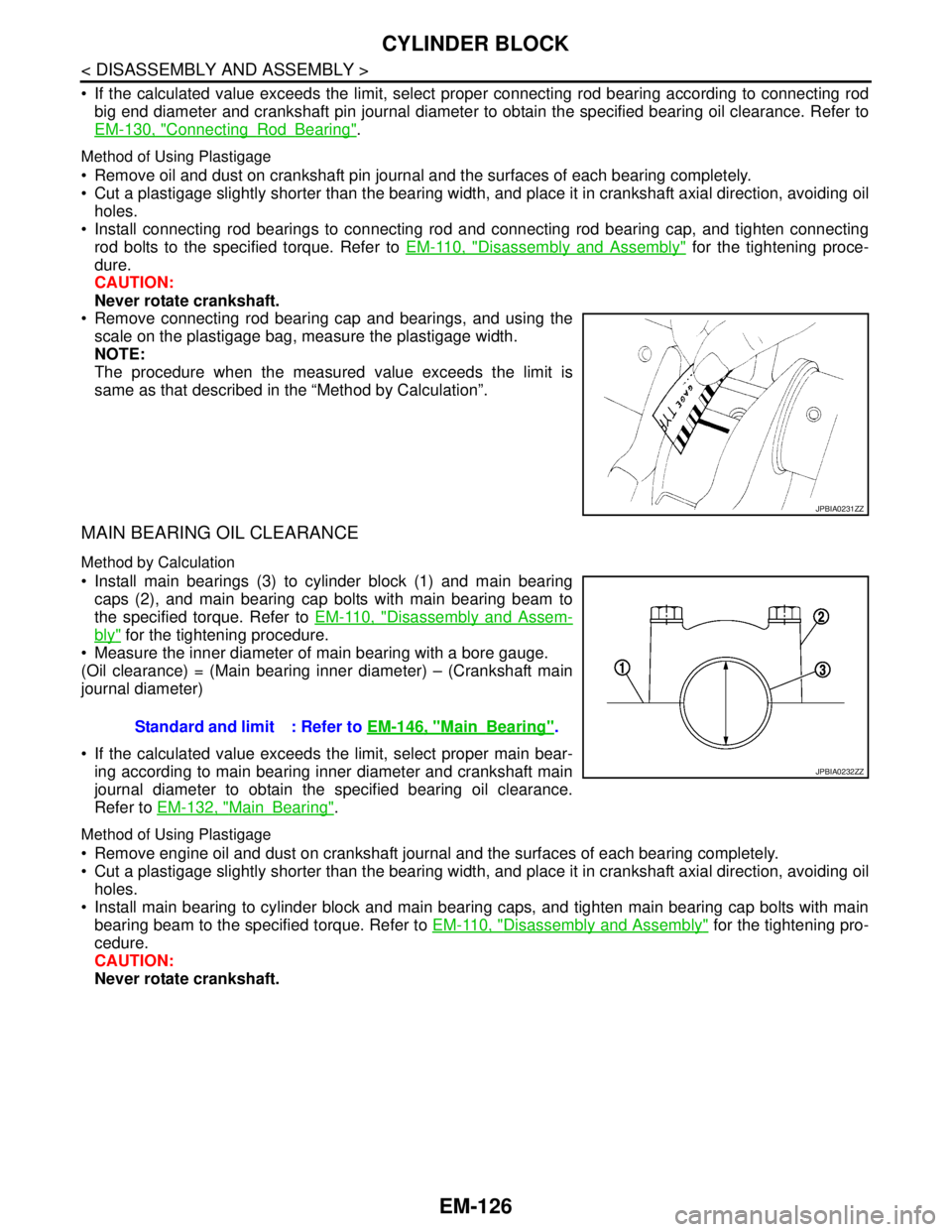
Remove connecting rod bearing cap and bearings, and using the
scale on the plastigage bag, measure the plastigage width.
NOTE:
The procedure when the measured value exceeds the limit is
same as that described in the “Method by Calculation”.
MAIN BEARING OIL CLEARANCE
Method by Calculation
Install main bearings (3) to cylinder block (1) and main bearing
caps (2), and main bearing cap bolts with main bearing beam to
the specified torque. Refer to EM-110, "
Disassembly and Assem-
bly" for the tightening procedure.
Measure the inner diameter of main bearing with a bore gauge.
(Oil clearance) = (Main bearing inner diameter) – (Crankshaft main
journal diameter)
If the calculated value exceeds the limit, select proper main bear-
ing according to main bearing inner diameter and crankshaft main
journal diameter to obtain the specified bearing oil clearance.
Refer to EM-132, "
MainBearing".
Method of Using Plastigage
Remove engine oil and dust on crankshaft journal and the surfaces of each bearing completely.
Cut a plastigage slightly shorter than the bearing width, and place it in crankshaft axial direction, avoiding oil
holes.
Install main bearing to cylinder block and main bearing caps, and tighten main bearing cap bolts with main
bearing beam to the specified torque. Refer to EM-110, "
Disassembly and Assembly" for the tightening pro-
cedure.
CAUTION:
Never rotate crankshaft.
JPBIA0231ZZ
Standard and limit : Refer to EM-146, "MainBearing".
JPBIA0232ZZ
Page 2010 of 5121
SERVICE DATA AND SPECIFICATIONS (SDS)
EM-135
< SERVICE DATA AND SPECIFICATIONS (SDS)
C
D
E
F
G
H
I
J
K
L
MA
EM
N
P O
SERVICE DATA AND SPECIFICATIONS (SDS)
SERVICE DATA AND SPECIFICATIONS (SDS)
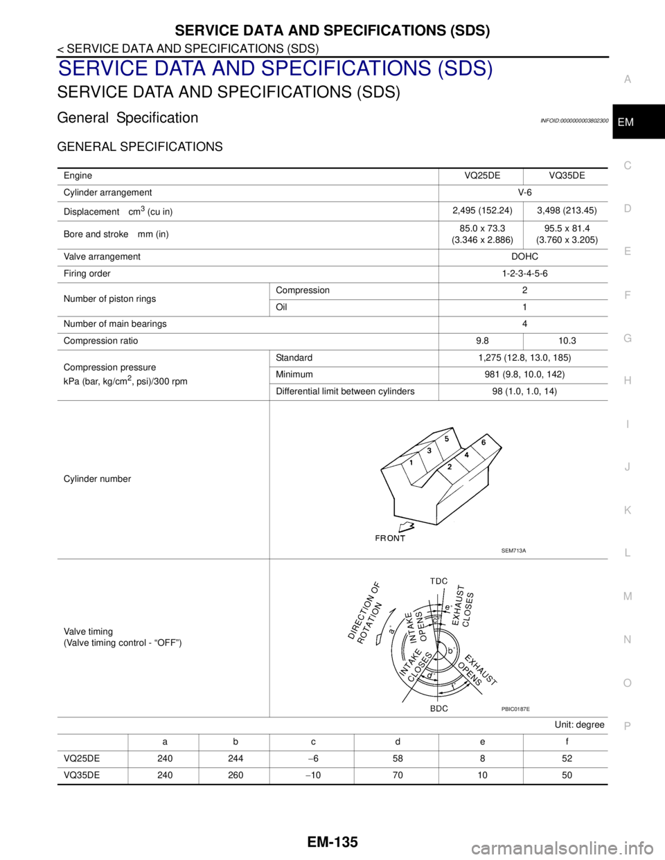
General SpecificationINFOID:0000000003802300
GENERAL SPECIFICATIONS
EngineVQ25DE VQ35DE
Cylinder arrangementV- 6
Displacement cm
3 (cu in)2,495 (152.24) 3,498 (213.45)
Bore and stroke mm (in)85.0 x 73.3
(3.346 x 2.886)95.5 x 81.4
(3.760 x 3.205)
Valve arrangementDOHC
Firing order1-2-3-4-5-6
Number of piston ringsCompression 2
Oil 1
Number of main bearings4
Compression ratio9.8 10.3
Compression pressure
kPa (bar, kg/cm
2, psi)/300 rpmStandard 1,275 (12.8, 13.0, 185)
Minimum 981 (9.8, 10.0, 142)
Differential limit between cylinders 98 (1.0, 1.0, 14)
Cylinder number
Valve timing
(Valve timing control - “OFF”)
Unit: degree
ab c d e f
VQ25DE 240 244−658852
VQ35DE 240 260−10 70 10 50
SEM713A
PBIC0187E
Page 2015 of 5121
EM-140
< SERVICE DATA AND SPECIFICATIONS (SDS)
SERVICE DATA AND SPECIFICATIONS (SDS)
Unit: mm (in)
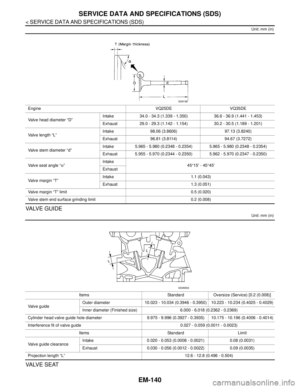
VA LV E G U I D E
Unit: mm (in)
VALVE SEAT
Engine VQ25DE VQ35DE
Valve head diameter “D”Intake 34.0 - 34.3 (1.339 - 1.350) 36.6 - 36.9 (1.441 - 1.453)
Exhaust 29.0 - 29.3 (1.142 - 1.154) 30.2 - 30.5 (1.189 - 1.201)
Valve length “L”Intake 98.06 (3.8606) 97.13 (3.8240)
Exhaust 96.81 (3.8114) 94.67 (3.7272)
Valve stem diameter “d”Intake 5.965 - 5.980 (0.2348 - 0.2354) 5.965 - 5.980 (0.2348 - 0.2354)
Exhaust 5.955 - 5.970 (0.2344 - 0.2350) 5.962 - 5.970 (0.2347 - 0.2350)
Valve seat angle “α”Intake
45°15′ - 45°45′
Exhaust
Valve margin “T”Intake 1.1 (0.043)
Exhaust 1.3 (0.051)
Valve margin “T” limit 0.5 (0.020)
Valve stem end surface grinding limit 0.2 (0.008)
SEM188
Items Standard Oversize (Service) [0.2 (0.008)]
Valve guideOuter diameter 10.023 - 10.034 (0.3946 - 0.3950) 10.223 - 10.234 (0.4025 - 0.4029)
Inner diameter (Finished size) 6.000 - 6.018 (0.2362 - 0.2369)
Cylinder head valve guide hole diameter 9.975 - 9.996 (0.3927 - 0.3935) 10.175 - 10.196 (0.4006 - 0.4014)
Interference fit of valve guide 0.027 - 0.059 (0.0011 - 0.0023)
Items Standard Limit
Valve guide clearanceIntake 0.020 - 0.053 (0.0008 - 0.0021) 0.08 (0.0031)
Exhaust 0.030 - 0.056 (0.0012 - 0.0022) 0.09 (0.0035)
Projection length “L” 12.6 - 12.8 (0.496 - 0.504)
SEM950E
Page 2018 of 5121
SERVICE DATA AND SPECIFICATIONS (SDS)
EM-143
< SERVICE DATA AND SPECIFICATIONS (SDS)
C
D
E
F
G
H
I
J
K
L
MA
EM
N
P O
Unit: mm (in)
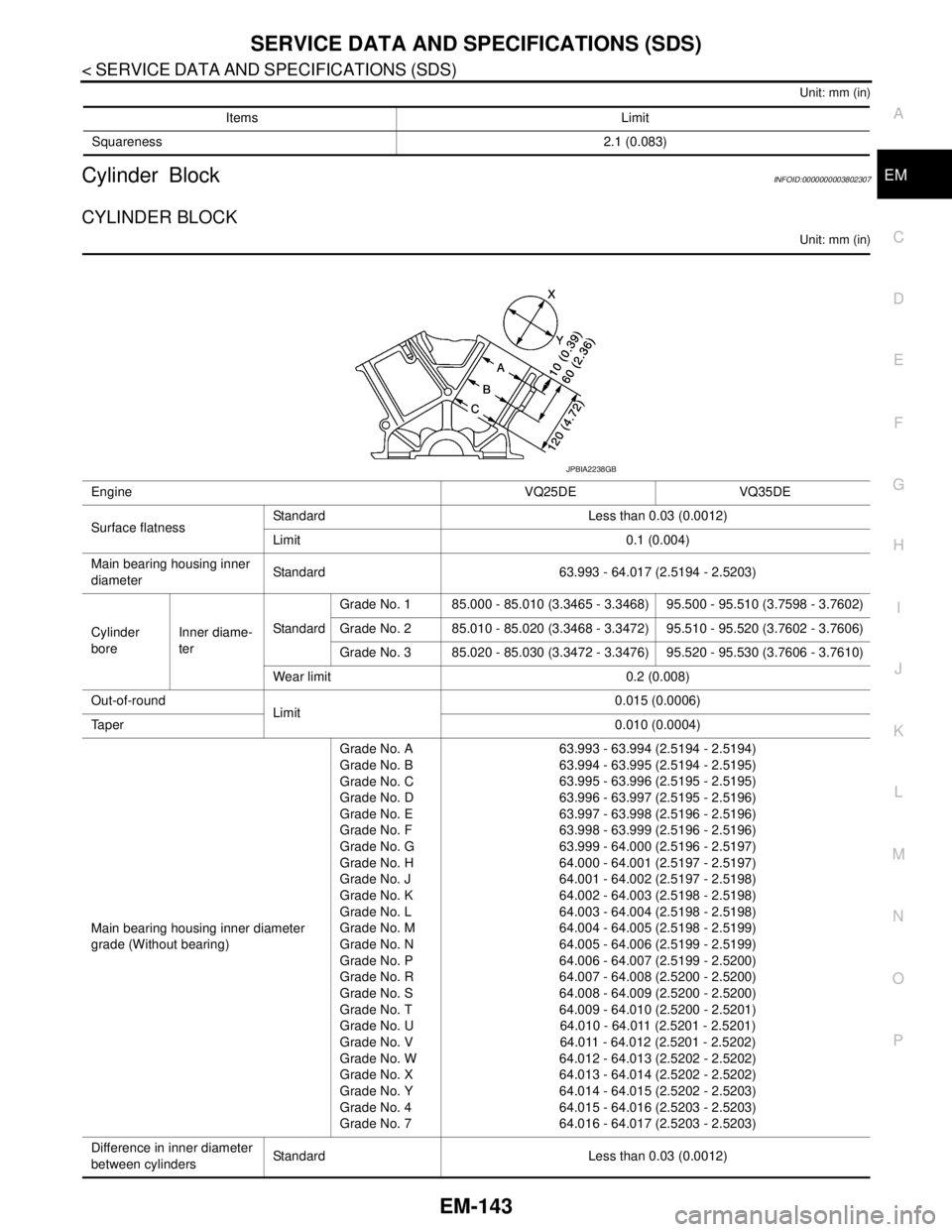
Cylinder BlockINFOID:0000000003802307
CYLINDER BLOCK
Unit: mm (in)
Items Limit
Squareness2.1 (0.083)
Engine VQ25DE VQ35DE
Surface flatnessStandard Less than 0.03 (0.0012)
Limit 0.1 (0.004)
Main bearing housing inner
diameterStandard 63.993 - 64.017 (2.5194 - 2.5203)
Cylinder
boreInner diame-
terStandardGrade No. 1 85.000 - 85.010 (3.3465 - 3.3468) 95.500 - 95.510 (3.7598 - 3.7602)
Grade No. 2 85.010 - 85.020 (3.3468 - 3.3472) 95.510 - 95.520 (3.7602 - 3.7606)
Grade No. 3 85.020 - 85.030 (3.3472 - 3.3476) 95.520 - 95.530 (3.7606 - 3.7610)
Wear limit 0.2 (0.008)
Out-of-round
Limit0.015 (0.0006)
Ta p e r 0.010 (0.0004)
Main bearing housing inner diameter
grade (Without bearing)Grade No. A
Grade No. B
Grade No. C
Grade No. D
Grade No. E
Grade No. F
Grade No. G
Grade No. H
Grade No. J
Grade No. K
Grade No. L
Grade No. M
Grade No. N
Grade No. P
Grade No. R
Grade No. S
Grade No. T
Grade No. U
Grade No. V
Grade No. W
Grade No. X
Grade No. Y
Grade No. 4
Grade No. 763.993 - 63.994 (2.5194 - 2.5194)
63.994 - 63.995 (2.5194 - 2.5195)
63.995 - 63.996 (2.5195 - 2.5195)
63.996 - 63.997 (2.5195 - 2.5196)
63.997 - 63.998 (2.5196 - 2.5196)
63.998 - 63.999 (2.5196 - 2.5196)
63.999 - 64.000 (2.5196 - 2.5197)
64.000 - 64.001 (2.5197 - 2.5197)
64.001 - 64.002 (2.5197 - 2.5198)
64.002 - 64.003 (2.5198 - 2.5198)
64.003 - 64.004 (2.5198 - 2.5198)
64.004 - 64.005 (2.5198 - 2.5199)
64.005 - 64.006 (2.5199 - 2.5199)
64.006 - 64.007 (2.5199 - 2.5200)
64.007 - 64.008 (2.5200 - 2.5200)
64.008 - 64.009 (2.5200 - 2.5200)
64.009 - 64.010 (2.5200 - 2.5201)
64.010 - 64.011 (2.5201 - 2.5201)
64.011 - 64.012 (2.5201 - 2.5202)
64.012 - 64.013 (2.5202 - 2.5202)
64.013 - 64.014 (2.5202 - 2.5202)
64.014 - 64.015 (2.5202 - 2.5203)
64.015 - 64.016 (2.5203 - 2.5203)
64.016 - 64.017 (2.5203 - 2.5203)
Difference in inner diameter
between cylindersStandard Less than 0.03 (0.0012)
JPBIA2238GB
Page 2021 of 5121
EM-146
< SERVICE DATA AND SPECIFICATIONS (SDS)
SERVICE DATA AND SPECIFICATIONS (SDS)
Unit: mm (in)
*: Total indicator reading
Main BearingINFOID:0000000003802308
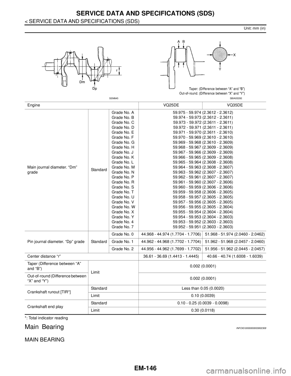
MAIN BEARING
Engine VQ25DE VQ35DE
Main journal diameter. “Dm”
gradeStandardGrade No. A
Grade No. B
Grade No. C
Grade No. D
Grade No. E
Grade No. F
Grade No. G
Grade No. H
Grade No. J
Grade No. K
Grade No. L
Grade No. M
Grade No. N
Grade No. P
Grade No. R
Grade No. S
Grade No. T
Grade No. U
Grade No. V
Grade No. W
Grade No. X
Grade No. Y
Grade No. 4
Grade No. 759.975 - 59.974 (2.3612 - 2.3612)
59.974 - 59.973 (2.3612 - 2.3611)
59.973 - 59.972 (2.3611 - 2.3611)
59.972 - 59.971 (2.3611 - 2.3611)
59.971 - 59.970 (2.3611 - 2.3610)
59.970 - 59.969 (2.3610 - 2.3610)
59.969 - 59.968 (2.3610 - 2.3609)
59.968 - 59.967 (2.3609 - 2.3609)
59.967 - 59.966 (2.3609 - 2.3609)
59.966 - 59.965 (2.3609 - 2.3608)
59.965 - 59.964 (2.3608 - 2.3608)
59.964 - 59.963 (2.3608 - 2.3607)
59.963 - 59.962 (2.3607 - 2.3607)
59.962 - 59.961 (2.3607 - 2.3607)
59.961 - 59.960 (2.3607 - 2.3606)
59.960 - 59.959 (2.3606 - 2.3606)
59.959 - 59.958 (2.3606 - 2.3605)
59.958 - 59.957 (2.3605 - 2.3605)
59.957 - 59.956 (2.3605 - 2.3605)
59.956 - 59.955 (2.3605 - 2.3604)
59.955 - 59.954 (2.3604 - 2.3604)
59.954 - 59.953 (2.3604 - 2.3603)
59.953 - 59.952 (2.3603 - 2.3603)
59.952 - 59.951 (2.3603 - 2.3603)
Pin journal diameter. “Dp” grade StandardGrade No. 0 44.968 - 44.974 (1.7704 - 1.7706) 51.968 - 51.974 (2.0460 - 2.0462)
Grade No. 1 44.962 - 44.968 (1.7702 - 1.7704) 51.962 - 51.968 (2.0457 - 2.0460)
Grade No. 2 44.956 - 44.962 (1.7699 - 1.7702) 51.956 - 51.962 (2.0445 - 2.0457)
Center distance “r” 36.61 - 36.69 (1.4413 - 1.4445) 40.66 - 40.74 (1.6008 - 1.6039)
Taper (Difference between “A”
and “B”)
Limit0.002 (0.0001)
Out-of-round (Difference between
“X” and “Y”)0.002 (0.0001)
Crankshaft runout [TIR*]Standard Less than 0.05 (0.0020)
Limit 0.10 (0.0039)
Crankshaft end playStandard 0.10 - 0.25 (0.0039 - 0.0098)
Limit 0.30 (0.0118)
SEM645SBIA0535E