Page 1953 of 5121
EM-78
< DISASSEMBLY AND ASSEMBLY >
ENGINE UNIT
ENGINE UNIT
DisassemblyINFOID:0000000003802279
1. Remove intake manifold collector. Refer to EM-28, "Exploded View".
2. Remove intake manifold. Refer to EM-32, "
Exploded View".
3. Remove exhaust manifold. Refer to EM-34, "
Exploded View".
4. Remove oil pan (lower). Refer to EM-38, "
Exploded View".
5. Remove ignition coil, spark plug and rocker cover. Refer to EM-49, "
Exploded View".
6. Remove fuel injector and fuel tube. Refer to EM-44, "
Exploded View".
7. Remove timing chain and rear timing chain case. Refer to EM-52, "
Exploded View" and EM-79, "Exploded
View".
8. Remove camshaft. Refer to EM-84, "
Exploded View".
9. Remove cylinder head. Refer to EM-96, "
Exploded View".
AssemblyINFOID:0000000003802280
Assembly in the reverse order of disassembly.
Page 1955 of 5121

EM-80
< DISASSEMBLY AND ASSEMBLY >
REAR TIMING CHAIN CASE
Disassembly and Assembly
INFOID:0000000003802282
DISASSEMBLY
1. Remove front timing chain case and timing chain. Refer to EM-52, "Exploded View".
2. Remove water pump. Refer to CO-18, "
Exploded View".
3. Remove oil pans (upper and lower) and oil strainer. Refer to EM-38, "
Exploded View".
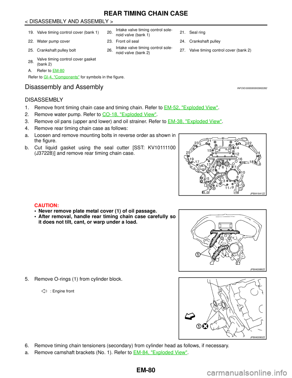
4. Remove rear timing chain case as follows:
a. Loosen and remove mounting bolts in reverse order as shown in
the figure.
b . C u t l i q u i d g a s k e t u s i n g t h e s e a l c u t t e r [ S S T: K V 1 0 1111 0 0
(J37228)] and remove rear timing chain case.
CAUTION:
Never remove plate metal cover (1) of oil passage.
After removal, handle rear timing chain case carefully so
it does not tilt, cant, or warp under a load.
5. Remove O-rings (1) from cylinder block.
6. Remove timing chain tensioners (secondary) from cylinder head as follows, if necessary.
a. Remove camshaft brackets (No. 1). Refer to EM-84, "
Exploded View".
19. Valve timing control cover (bank 1) 20.Intake valve timing control sole-
noid valve (bank 1)21. Seal ring
22. Water pump cover 23. Front oil seal 24. Crankshaft pulley
25. Crankshaft pulley bolt 26.Intake valve timing control sole-
noid valve (bank 2)27. Valve timing control cover (bank 2)
28.Valve timing control cover gasket
(bank 2)
A. Refer to EM-80
Refer to GI-4, "Components" for symbols in the figure.
JPBIA1641ZZ
JPBIA0088ZZ
: Engine front
JPBIA0090ZZ
Page 1956 of 5121
REAR TIMING CHAIN CASE
EM-81
< DISASSEMBLY AND ASSEMBLY >
C
D
E
F
G
H
I
J
K
L
MA
EM
N
P O
b. Remove timing chain tensioners (secondary) (1) with a stopper
pin (B) attached.
7. Use a scraper to remove all traces of old liquid gasket from front and rear timing chain cases, and oppo-
site mating surfaces.
Remove old liquid gasket from bolt hole (B) and thread.
ASSEMBLY
1. Install rear timing chain case as follows:
Install new O-rings (1) onto cylinder block.
a. Apply liquid gasket with the tube presser (commercial service tool) to rear timing chain case back side as
shown in the figure.
Use Genuine Liquid Gasket or equivalent.
CAUTION:
For “A” in the figure, completely wipe out liquid gasket extended on a portion touching at engine
coolant.
A : Bank 1
B : Bank 2
JPBIA1727ZZ
A : Remove sticking old liquid gasket
JPBIA0051ZZ
: Engine front
JPBIA0090ZZ
Page 1960 of 5121
CAMSHAFT
EM-85
< DISASSEMBLY AND ASSEMBLY >
C
D
E
F
G
H
I
J
K
L
MA
EM
N
P O
2. Loosen camshaft sensor bracket bolts in reverse order as
shown in the figure.
NOTE:
The order of loosening bolts in the same for bank 1 and bank 2.
3. Remove camshaft brackets.
Mark camshafts, camshaft brackets and bolts so they are placed in the same position and direction for
installation.
Equally loosen camshaft bracket bolts in several steps in
reverse order as shown in the figure.
4. Remove camshafts.
5. Remove valve lifters.
Identify installation positions, and store them without mixing them up.
6. Remove timing chain tensioners (secondary) (1) from cylinder
head.
Remove timing chain tensioner (secondary) with its stopper
pin (C) attached.
NOTE:
Stopper pin should be attached when timing chain (secondary)
is removed.
INSTALLATION
: Engine front
JPBIA1960ZZ
: Engine front
JPBIA0257ZZ
A: Bank 1
B: Bank 2
JPBIA0121ZZ
Page 1961 of 5121

EM-86
< DISASSEMBLY AND ASSEMBLY >
CAMSHAFT
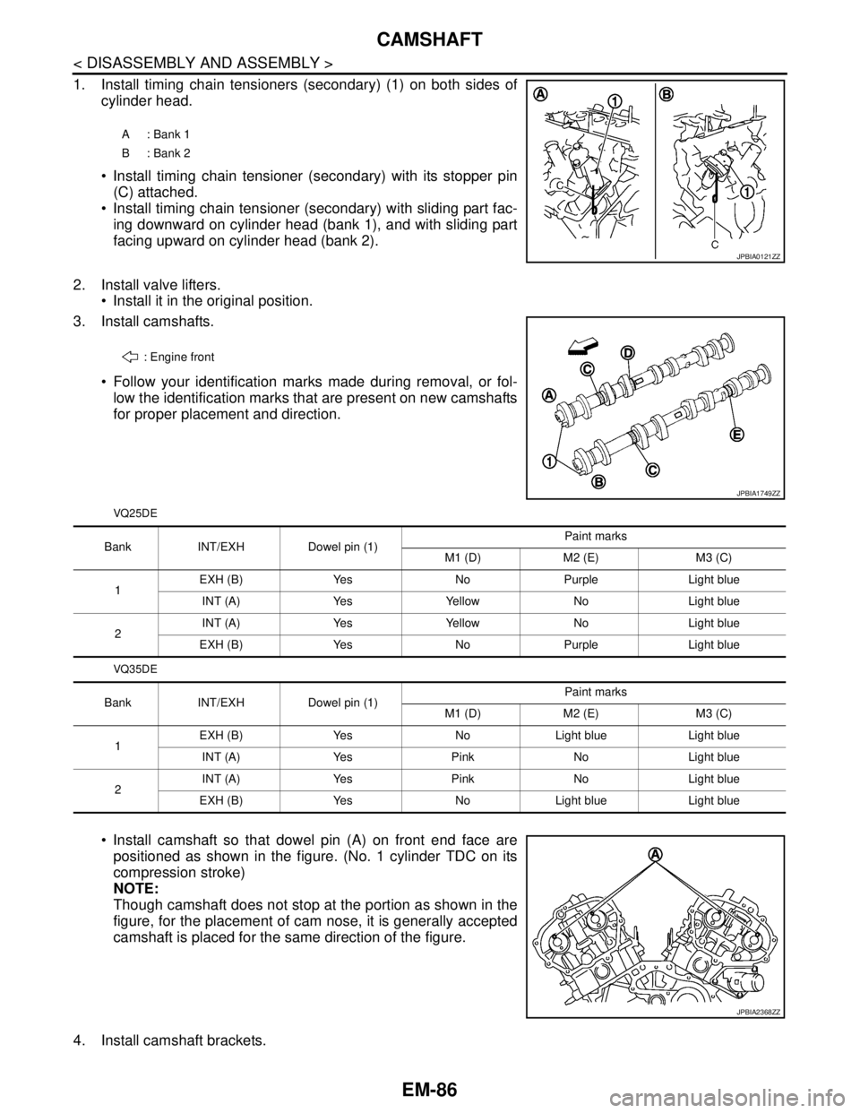
1. Install timing chain tensioners (secondary) (1) on both sides of
cylinder head.
Install timing chain tensioner (secondary) with its stopper pin
(C) attached.
Install timing chain tensioner (secondary) with sliding part fac-
ing downward on cylinder head (bank 1), and with sliding part
facing upward on cylinder head (bank 2).
2. Install valve lifters.
Install it in the original position.
3. Install camshafts.
Follow your identification marks made during removal, or fol-
low the identification marks that are present on new camshafts
for proper placement and direction.
VQ25DE
VQ35DE
Install camshaft so that dowel pin (A) on front end face are
positioned as shown in the figure. (No. 1 cylinder TDC on its
compression stroke)
NOTE:
Though camshaft does not stop at the portion as shown in the
figure, for the placement of cam nose, it is generally accepted
camshaft is placed for the same direction of the figure.
4. Install camshaft brackets.
A: Bank 1
B: Bank 2
JPBIA0121ZZ
: Engine front
JPBIA1749ZZ
Bank INT/EXH Dowel pin (1)Paint marks
M1 (D) M2 (E) M3 (C)
1EXH (B) Yes No Purple Light blue
INT (A) Yes Yellow No Light blue
2INT (A) Yes Yellow No Light blue
EXH (B) Yes No Purple Light blue
Bank INT/EXH Dowel pin (1)Paint marks
M1 (D) M2 (E) M3 (C)
1EXH (B) Yes No Light blue Light blue
INT (A) Yes Pink No Light blue
2INT (A) Yes Pink No Light blue
EXH (B) Yes No Light blue Light blue
JPBIA2368ZZ
Page 1962 of 5121
CAMSHAFT
EM-87
< DISASSEMBLY AND ASSEMBLY >
C
D
E
F
G
H
I
J
K
L
MA
EM
N
P O
Remove foreign material completely from camshaft bracket backside and from cylinder head installation
face.
Install camshaft bracket in original position and direction as
shown in the figure.
Install camshaft brackets (No. 2 to 4) aligning the stamp marks
(A) as shown in the figure.
NOTE:
There are no identification marks indicating left and right for
camshaft bracket (No. 1).
Apply liquid gasket to mating surface of camshaft bracket (No.
1) as shown on bank 1 and bank 2.
Use Genuine Liquid Gasket or equivalent.
A : No. 1
B : No. 2
C : No. 3
D : No. 4
E: Bank 1
F : Exhaust side
G : Intake side
H: Bank 2
I : Intake side
J : Exhaust side
: Engine front
JPBIA0258ZZ
B: Bank 1
C: Bank 2
: Engine front
JPBIA0272ZZ
a : 8.5 mm (0.335 in)
b : 2 mm (0.08 in)
c : Clearance 5 mm (0.20 in)
d: φ2.0 - 2.3 mm (0.08 - 0.12 in)
* : Apply liquid gasket to rear timing chain case side
JPBIA0255ZZ
Page 1963 of 5121

EM-88
< DISASSEMBLY AND ASSEMBLY >
CAMSHAFT
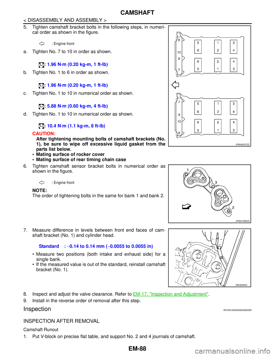
5. Tighten camshaft bracket bolts in the following steps, in numeri-
cal order as shown in the figure.
a. Tighten No. 7 to 10 in order as shown.
b. Tighten No. 1 to 6 in order as shown.
c. Tighten No. 1 to 10 in numerical order as shown.
d. Tighten No. 1 to 10 in numerical order as shown.
CAUTION:
After tightening mounting bolts of camshaft brackets (No.
1), be sure to wipe off excessive liquid gasket from the
parts list below.
Mating surface of rocker cover
Mating surface of rear timing chain case
6. Tighten camshaft sensor bracket bolts in numerical order as
shown in the figure.
NOTE:
The order of tightening bolts in the same for bank 1 and bank 2.
7. Measure difference in levels between front end faces of cam-
shaft bracket (No. 1) and cylinder head.
Measure two positions (both intake and exhaust side) for a
single bank.
If the measured value is out of the standard, reinstall camshaft
bracket (No. 1).
8. Inspect and adjust the valve clearance. Refer to EM-17, "
Inspection and Adjustment".
9. Install in the reverse order of removal after this step.
InspectionINFOID:0000000003802285
INSPECTION AFTER REMOVAL
Camshaft Runout
1. Put V-block on precise flat table, and support No. 2 and 4 journals of camshaft.
: Engine front
: 1.96 N·m (0.20 kg-m, 1 ft-lb)
: 1.96 N·m (0.20 kg-m, 1 ft-lb)
: 5.88 N·m (0.60 kg-m, 4 ft-lb)
: 10.4 N·m (1.1 kg-m, 8 ft-lb)
: Engine front
JPBIA0257ZZ
JPBIA1960ZZ
Standard : −0.14 to 0.14 mm (−0.0055 to 0.0055 in)
EMQ0044D
Page 1966 of 5121

CAMSHAFT
EM-91
< DISASSEMBLY AND ASSEMBLY >
C
D
E
F
G
H
I
J
K
L
MA
EM
N
P O
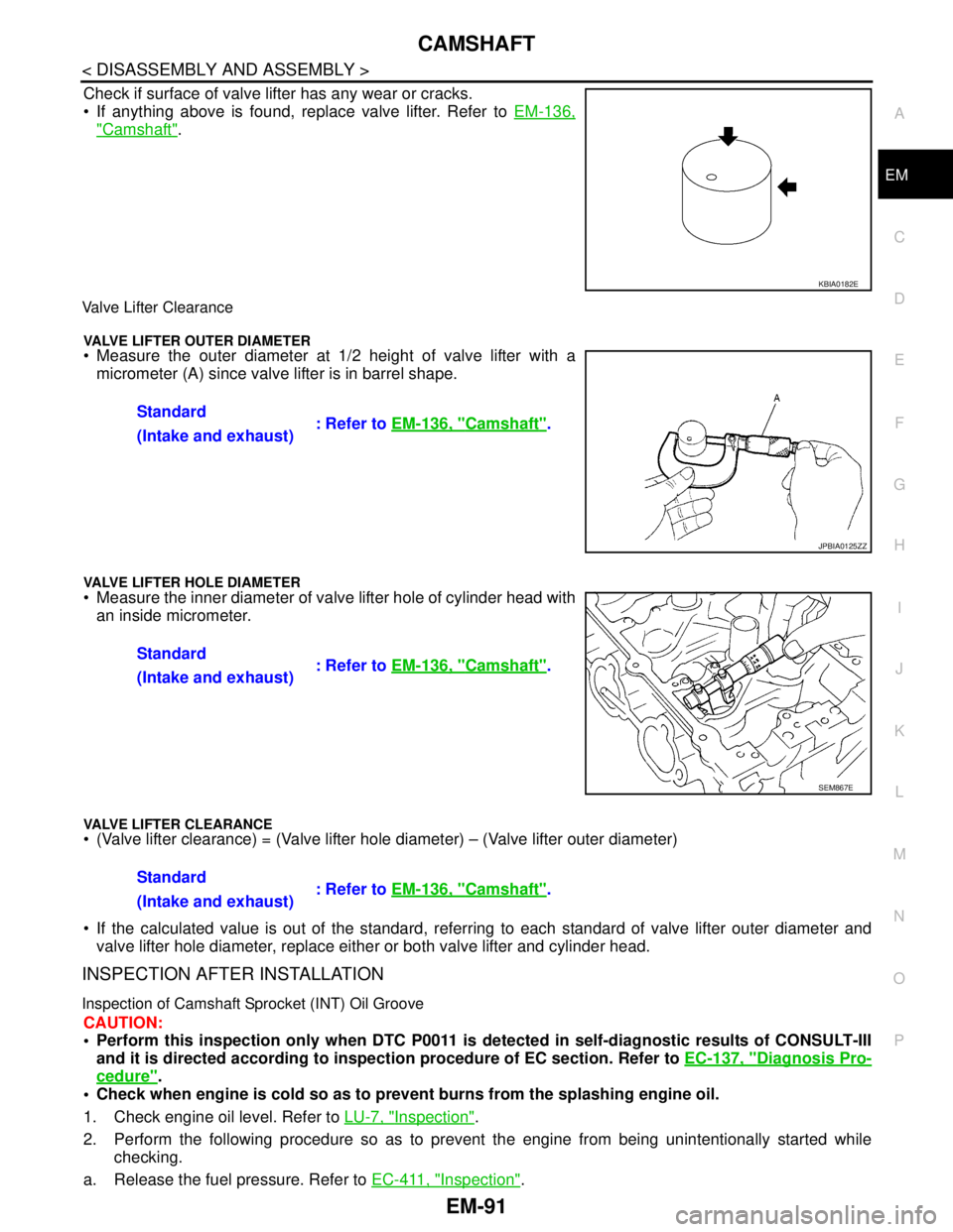
Check if surface of valve lifter has any wear or cracks.
If anything above is found, replace valve lifter. Refer to EM-136,
"Camshaft".
Valve Lifter Clearance
VALVE LIFTER OUTER DIAMETER Measure the outer diameter at 1/2 height of valve lifter with a
micrometer (A) since valve lifter is in barrel shape.
VALVE LIFTER HOLE DIAMETER Measure the inner diameter of valve lifter hole of cylinder head with
an inside micrometer.
VALVE LIFTER CLEARANCE (Valve lifter clearance) = (Valve lifter hole diameter) – (Valve lifter outer diameter)
If the calculated value is out of the standard, referring to each standard of valve lifter outer diameter and
valve lifter hole diameter, replace either or both valve lifter and cylinder head.
INSPECTION AFTER INSTALLATION
Inspection of Camshaft Sprocket (INT) Oil Groove
CAUTION:
Perform this inspection only when DTC P0011 is detected in self-diagnostic results of CONSULT-III
and it is directed according to inspection procedure of EC section. Refer to EC-137, "
Diagnosis Pro-
cedure".
Check when engine is cold so as to prevent burns from the splashing engine oil.
1. Check engine oil level. Refer to LU-7, "
Inspection".
2. Perform the following procedure so as to prevent the engine from being unintentionally started while
checking.
a. Release the fuel pressure. Refer to EC-411, "
Inspection".
KBIA0182E
Standard
: Refer to EM-136, "Camshaft".
(Intake and exhaust)
JPBIA0125ZZ
Standard
: Refer to EM-136, "Camshaft".
(Intake and exhaust)
SEM867E
Standard
: Refer to EM-136, "Camshaft".
(Intake and exhaust)