2008 NISSAN TEANA sensor
[x] Cancel search: sensorPage 1963 of 5121
EM-88
< DISASSEMBLY AND ASSEMBLY >
CAMSHAFT
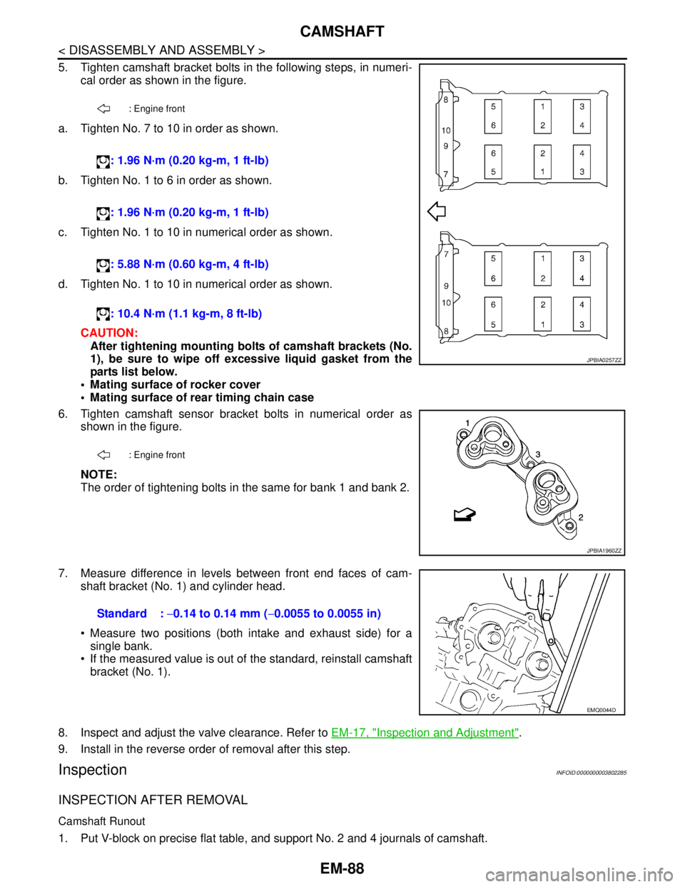
5. Tighten camshaft bracket bolts in the following steps, in numeri-
cal order as shown in the figure.
a. Tighten No. 7 to 10 in order as shown.
b. Tighten No. 1 to 6 in order as shown.
c. Tighten No. 1 to 10 in numerical order as shown.
d. Tighten No. 1 to 10 in numerical order as shown.
CAUTION:
After tightening mounting bolts of camshaft brackets (No.
1), be sure to wipe off excessive liquid gasket from the
parts list below.
Mating surface of rocker cover
Mating surface of rear timing chain case
6. Tighten camshaft sensor bracket bolts in numerical order as
shown in the figure.
NOTE:
The order of tightening bolts in the same for bank 1 and bank 2.
7. Measure difference in levels between front end faces of cam-
shaft bracket (No. 1) and cylinder head.
Measure two positions (both intake and exhaust side) for a
single bank.
If the measured value is out of the standard, reinstall camshaft
bracket (No. 1).
8. Inspect and adjust the valve clearance. Refer to EM-17, "
Inspection and Adjustment".
9. Install in the reverse order of removal after this step.
InspectionINFOID:0000000003802285
INSPECTION AFTER REMOVAL
Camshaft Runout
1. Put V-block on precise flat table, and support No. 2 and 4 journals of camshaft.
: Engine front
: 1.96 N·m (0.20 kg-m, 1 ft-lb)
: 1.96 N·m (0.20 kg-m, 1 ft-lb)
: 5.88 N·m (0.60 kg-m, 4 ft-lb)
: 10.4 N·m (1.1 kg-m, 8 ft-lb)
: Engine front
JPBIA0257ZZ
JPBIA1960ZZ
Standard : −0.14 to 0.14 mm (−0.0055 to 0.0055 in)
EMQ0044D
Page 1983 of 5121
EM-108
< DISASSEMBLY AND ASSEMBLY >
CYLINDER BLOCK
VQ35DE
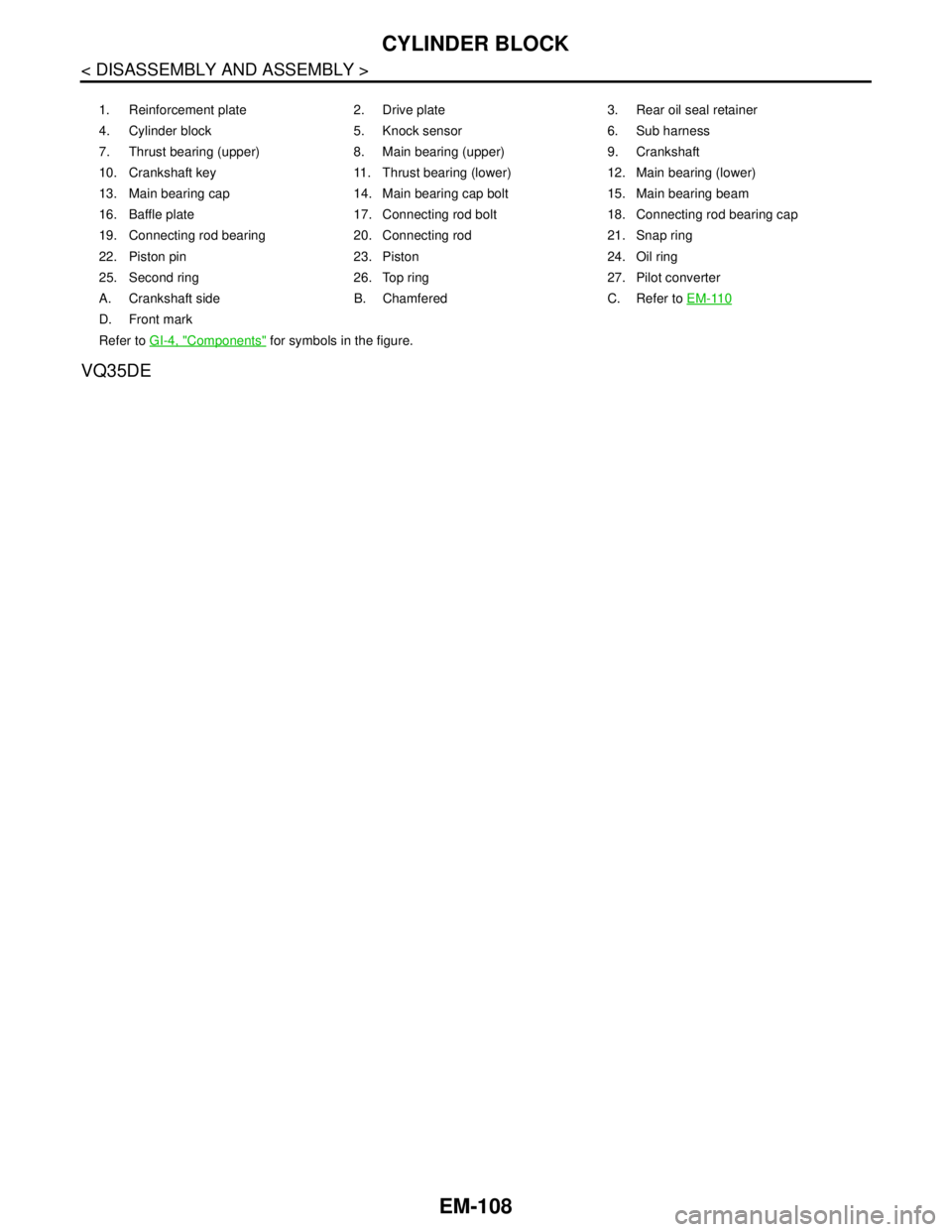
1. Reinforcement plate 2. Drive plate 3. Rear oil seal retainer
4. Cylinder block 5. Knock sensor 6. Sub harness
7. Thrust bearing (upper) 8. Main bearing (upper) 9. Crankshaft
10. Crankshaft key 11. Thrust bearing (lower) 12. Main bearing (lower)
13. Main bearing cap 14. Main bearing cap bolt 15. Main bearing beam
16. Baffle plate 17. Connecting rod bolt 18. Connecting rod bearing cap
19. Connecting rod bearing 20. Connecting rod 21. Snap ring
22. Piston pin 23. Piston 24. Oil ring
25. Second ring 26. Top ring 27. Pilot converter
A. Crankshaft side B. Chamfered C. Refer to EM-110
D. Front mark
Refer to GI-4, "
Components" for symbols in the figure.
Page 1984 of 5121
CYLINDER BLOCK
EM-109
< DISASSEMBLY AND ASSEMBLY >
C
D
E
F
G
H
I
J
K
L
MA
EM
N
P O
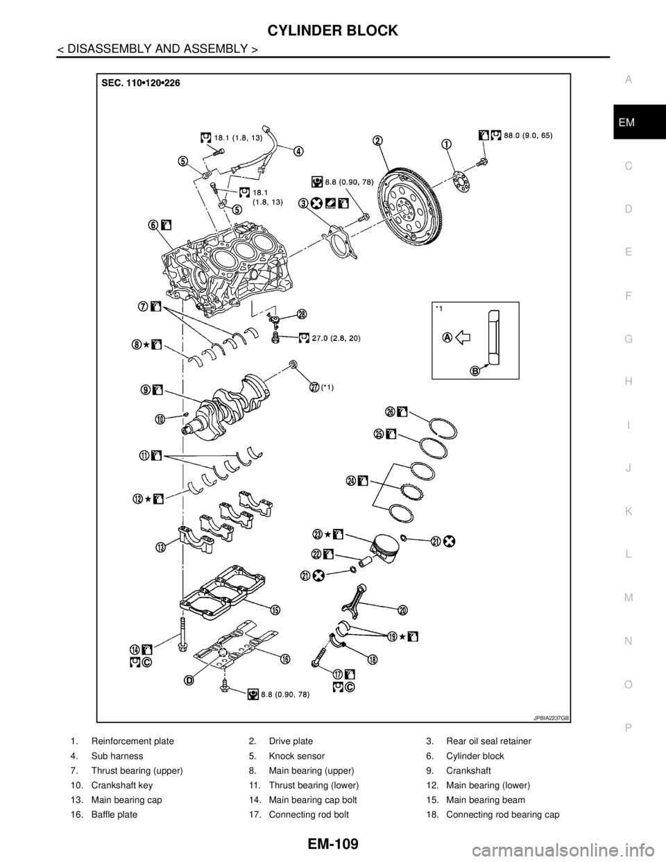
1. Reinforcement plate 2. Drive plate 3. Rear oil seal retainer
4. Sub harness 5. Knock sensor 6. Cylinder block
7. Thrust bearing (upper) 8. Main bearing (upper) 9. Crankshaft
10. Crankshaft key 11. Thrust bearing (lower) 12. Main bearing (lower)
13. Main bearing cap 14. Main bearing cap bolt 15. Main bearing beam
16. Baffle plate 17. Connecting rod bolt 18. Connecting rod bearing cap
JPBIA2237GB
Page 1985 of 5121
EM-110
< DISASSEMBLY AND ASSEMBLY >
CYLINDER BLOCK
Disassembly and Assembly
INFOID:0000000003802294
DISASSEMBLY
1. Remove the following parts:
Intake manifold collector: Refer to EM-28, "
Exploded View".
Intake manifold: Refer to EM-32, "
Exploded View".
Oil pans (lower and upper): Refer to EM-38, "
Exploded View".
Front and rear timing chain case: Refer to EM-79, "
Exploded View".
Cylinder head: Refer to EM-96, "
Exploded View".
2. Remove knock sensor.
CAUTION:
Carefully handle sensor avoiding shocks.
3. Remove rear oil seal retainer.
Remove by inserting screwdriver between main bearing cap and rear oil seal retainer.
CAUTION:
If rear oil seal retainer is removed, replace it with new one.
NOTE:
Regard both rear oil seal and retainer as an assembly.
4. Remove baffle plate from main bearing beam.
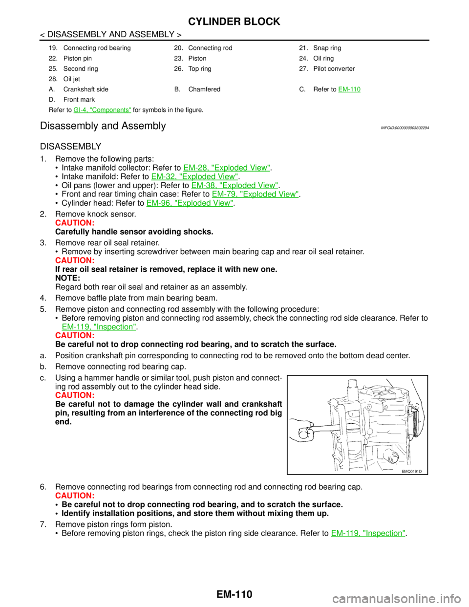
5. Remove piston and connecting rod assembly with the following procedure:
Before removing piston and connecting rod assembly, check the connecting rod side clearance. Refer to
EM-119, "
Inspection".
CAUTION:
Be careful not to drop connecting rod bearing, and to scratch the surface.
a. Position crankshaft pin corresponding to connecting rod to be removed onto the bottom dead center.
b. Remove connecting rod bearing cap.
c. Using a hammer handle or similar tool, push piston and connect-
ing rod assembly out to the cylinder head side.
CAUTION:
Be careful not to damage the cylinder wall and crankshaft
pin, resulting from an interference of the connecting rod big
end.
6. Remove connecting rod bearings from connecting rod and connecting rod bearing cap.
CAUTION:
Be careful not to drop connecting rod bearing, and to scratch the surface.
Identify installation positions, and store them without mixing them up.
7. Remove piston rings form piston.
Before removing piston rings, check the piston ring side clearance. Refer to EM-119, "
Inspection".
19. Connecting rod bearing 20. Connecting rod 21. Snap ring
22. Piston pin 23. Piston 24. Oil ring
25. Second ring 26. Top ring 27. Pilot converter
28. Oil jet
A. Crankshaft side B. Chamfered C. Refer to EM-110
D. Front mark
Refer to GI-4, "
Components" for symbols in the figure.
EMQ0191D
Page 1993 of 5121
EM-118
< DISASSEMBLY AND ASSEMBLY >
CYLINDER BLOCK
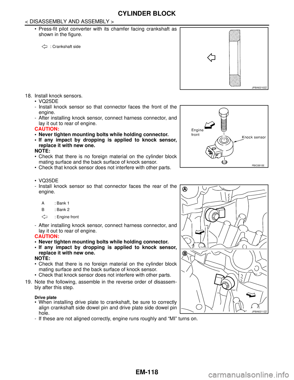
Press-fit pilot converter with its chamfer facing crankshaft as
shown in the figure.
18. Install knock sensors.
VQ25DE
- Install knock sensor so that connector faces the front of the
engine.
- After installing knock sensor, connect harness connector, and
lay it out to rear of engine.
CAUTION:
Never tighten mounting bolts while holding connector.
If any impact by dropping is applied to knock sensor,
replace it with new one.
NOTE:
Check that there is no foreign material on the cylinder block
mating surface and the back surface of knock sensor.
Check that knock sensor does not interfere with other parts.
VQ35DE
- Install knock sensor so that connector faces the rear of the
engine.
- After installing knock sensor, connect harness connector, and
lay it out to rear of engine.
CAUTION:
Never tighten mounting bolts while holding connector.
If any impact by dropping is applied to knock sensor,
replace it with new one.
NOTE:
Check that there is no foreign material on the cylinder block
mating surface and the back surface of knock sensor.
Check that knock sensor does not interfere with other parts.
19. Note the following, assemble in the reverse order of disassem-
bly after this step.
Drive plate When installing drive plate to crankshaft, be sure to correctly
align crankshaft side dowel pin and drive plate side dowel pin
hole.
- If these are not aligned correctly, engine runs roughly and “MI” turns on.
: Crankshaft side
JPBIA0210ZZ
PBIC0810E
A: Bank 1
B: Bank 2
: Engine front
JPBIA0211ZZ
Page 2030 of 5121
EXL-1
DRIVER CONTROLS
C
DE
F
G H
I
J
K
M
SECTION EXL
A
B
EXL
N
O P
CONTENTS
EXTERIOR LIGHTING SYSTEM
XENON TYPE
BASIC INSPECTION ....... .............................
7
DIAGNOSIS AND REPAIR WORKFLOW ..... .....7
Work Flow ........................................................... ......7
INSPECTION AND ADJUSTMENT .....................9
ADDITIONAL SERVICE WHEN REPLACING
CONTROL UNIT .................................................... ......
9
ADDITIONAL SERVICE WHEN REPLACING
CONTROL UNIT : Description ..................................
9
ADDITIONAL SERVICE WHEN REPLACING
CONTROL UNIT : Special Repair Requirement .......
9
CONFIGURATION (HEADLAMP LEVELIZER) .... ......9
CONFIGURATION (HEADLAMP LEVELIZER) :
Description ................................................................
9
CONFIGURATION (HEADLAMP LEVELIZER) :
Special Repair Requirement .....................................
9
SENSOR INITIALIZE ............................................. ......9
SENSOR INITIALIZE : Description .........................10
SENSOR INITIALIZE : Special Repair Require-
ment (HEADLAMP AIMING CONTROL SYSTEM)
....
10
FUNCTION DIAGNOSIS ..............................11
HEADLAMP SYSTEM .................................... ....11
System Diagram .................................................. ....11
System Description .................................................11
Component Parts Location ......................................12
Component Description ..........................................12
AUTO LIGHT SYSTEM ......................................13
System Diagram .................................................. ....13
System Description .................................................13
Component Parts Location ......................................14
Component Description ..........................................14
HEADLAMP AIMING CONTROL SYSTEM
(AUTO) ..............................................................
15
System Diagram .................................................. ....15
System Description ..................................................15
Component Parts Location ......................................16
Component Description ...........................................16
FRONT FOG LAMP SYSTEM ...........................17
System Diagram ......................................................17
System Description ..................................................17
Component Parts Location ......................................18
Component Description ..........................................18
TURN SIGNAL AND HAZARD WARNING
LAMP SYSTEM .................................................
19
System Diagram ......................................................19
System Description ..................................................19
Component Parts Location ......................................20
Component Description ..........................................20
PARKING, LICENSE PLATE AND TAIL
LAMPS SYSTEM ..............................................
21
System Diagram .................................................. ....21
System Description ..................................................21
Component Parts Location ......................................22
Component Description ..........................................22
REAR FOG LAMP SYSTEM .............................23
System Diagram ......................................................23
System Description ..................................................23
Component Parts Location ......................................24
Component Description ..........................................24
EXTERIOR LAMP BATTERY SAVER SYS-
TEM ...................................................................
25
System Diagram ......................................................25
System Description ..................................................25
Component Parts Location ......................................26
Component Description ..........................................26
DIAGNOSIS SYSTEM (BCM) ...........................27
Page 2031 of 5121

EXL-2
COMMON ITEM ........................................................27
COMMON ITEM : CONSULT-III Function (BCM -
COMMON ITEM) ....................................................
27
HEADLAMP ..............................................................28
HEADLAMP : CONSULT-III Function (BCM -
HEAD LAMP) ..........................................................
28
FLASHER ..................................................................30
FLASHER : CONSULT-III Function (BCM -
FLASHER) ..............................................................
30
DIAGNOSIS SYSTEM (IPDM E/R) ....................32
Diagnosis Description .............................................32
CONSULT-III Function (IPDM E/R) ........................34
DIAGNOSIS SYSTEM (HEADLAMP LEVEL-
IZER) ..................................................................
37
CONSULT-III Functions (HEADLAMP LEVELIZ-
ER) .........................................................................
37
COMPONENT DIAGNOSIS ........................38
B2080 ECU TROUBLE ......................................38
Description ..............................................................38
DTC Logic ...............................................................38
Diagnosis Procedure ..............................................38
B2081 INITIAL NOT DONE ...............................39
DTC Logic ...............................................................39
Diagnosis Procedure ..............................................39
B2082 SENSOR OUT OF RANGE ....................40
DTC Logic ...............................................................40
Diagnosis Procedure ..............................................40
B2083 SEN SIG NOT PLAUSIBLE ...................41
DTC Logic ...............................................................41
Diagnosis Procedure ..............................................41
B2084 VOLTAGE UNDER LIMIT ......................42
DTC Logic ...............................................................42
Diagnosis Procedure ..............................................42
B2085 LOWBEAM SIG OPEN LINE .................43
Description ..............................................................43
DTC Logic ...............................................................43
Diagnosis Procedure ..............................................43
B2086 FRQ. OVER LIMIT ..................................45
Description ..............................................................45
DTC Logic ...............................................................45
Diagnosis Procedure ..............................................45
B2087 SHORT TO GROUND ............................47
DTC Logic ...............................................................47
Diagnosis Procedure ..............................................47
B2088 SHORT TO BATTERY ...........................48
DTC Logic ...............................................................48
Diagnosis Procedure ..............................................48
B208A PARA NOT PROG .................................49
DTC Logic ...............................................................49
Diagnosis Procedure ...............................................49
POWER SUPPLY AND GROUND CIRCUIT .....50
BCM (BODY CONTROL MODULE) ..........................50
BCM (BODY CONTROL MODULE) : Diagnosis
Procedure ...............................................................
50
IPDM E/R (INTELLIGENT POWER DISTRIBU-
TION MODULE ENGINE ROOM) ..............................
50
IPDM E/R (INTELLIGENT POWER DISTRIBU-
TION MODULE ENGINE ROOM) : Diagnosis Pro-
cedure .....................................................................
50
AUTO LEVELIZER CONTROL UNIT ........................51
AUTO LEVELIZER CONTROL UNIT : Diagnosis
Procedure ...............................................................
51
EXTERIOR LAMP FUSE ...................................53
Description ..............................................................53
Diagnosis Procedure ...............................................53
HEADLAMP (HI) CIRCUIT ................................54
Component Function Check ...................................54
Diagnosis Procedure ...............................................54
HEADLAMP (LO) CIRCUIT ...............................56
Component Function Check ...................................56
Diagnosis Procedure ...............................................56
XENON HEADLAMP .........................................58
Description ..............................................................58
Diagnosis Procedure ...............................................58
HEADLAMP LEVELIZER CIRCUIT ..................60
Description ..............................................................60
Component Function Check ...................................60
Diagnosis Procedure ...............................................60
FRONT FOG LAMP CIRCUIT ...........................62
Component Function Check ...................................62
Diagnosis Procedure ...............................................62
PARKING LAMP CIRCUIT ................................64
Component Function Check ...................................64
Diagnosis Procedure ...............................................64
TURN SIGNAL LAMP CIRCUIT ........................66
Description ..............................................................66
Component Function Check ...................................66
Diagnosis Procedure ...............................................66
OPTICAL SENSOR ...........................................69
Description ..............................................................69
Component Function Check ...................................69
Diagnosis Procedure ...............................................69
HAZARD SWITCH .............................................72
Component Function Check ...................................72
Diagnosis Procedure ...............................................72
Page 2033 of 5121

EXL-4
OPTICAL SENSOR .........................................185
Exploded View .......................................................185
Removal and Installation .......................................185
LIGHTING & TURN SIGNAL SWITCH ............186
Exploded View .......................................................186
Removal and Installation .......................................186
HAZARD SWITCH ...........................................187
Exploded View .......................................................187
Removal and Installation .......................................187
SIDE TURN SIGNAL LAMP ............................188
Exploded View .......................................................188
Removal and Installation .......................................188
AUTO LEVELIZER CONTROL UNIT ..............190
Exploded View .......................................................190
Removal and Installation .......................................190
REAR COMBINATION LAMP .........................191
Exploded View .......................................................191
Removal and Installation .......................................191
Replacement .........................................................192
HIGH-MOUNTED STOP LAMP .......................193
Exploded View .......................................................193
Removal and Installation .......................................193
REAR FOG LAMP ...........................................194
Exploded View .......................................................194
Removal and Installation .......................................194
Replacement .........................................................194
LICENSE PLATE LAMP ..................................195
Exploded View .......................................................195
Removal and Installation .......................................195
Replacement .........................................................195
SERVICE DATA AND SPECIFICATIONS
(SDS) ..........................................................
197
SERVICE DATA AND SPECIFICATIONS
(SDS) ................................................................
197
Bulb Specifications ................................................197
HALOGEN TYPE
BASIC INSPECTION ..................................
198
DIAGNOSIS AND REPAIR WORKFLOW .......198
Work Flow ..............................................................198
FUNCTION DIAGNOSIS ............................200
HEADLAMP SYSTEM .....................................200
System Diagram ....................................................200
System Description ................................................200
Component Parts Location ....................................201
Component Description ........................................201
AUTO LIGHT SYSTEM ....................................202
System Diagram ....................................................202
System Description ...............................................202
Component Parts Location ...................................203
Component Description ........................................203
FRONT FOG LAMP SYSTEM ..........................204
System Diagram ...................................................204
System Description ...............................................204
Component Parts Location ...................................205
Component Description ........................................205
TURN SIGNAL AND HAZARD WARNING
LAMP SYSTEM ................................................
206
System Diagram ...................................................206
System Description ...............................................206
Component Parts Location ...................................207
Component Description ........................................207
PARKING, LICENSE PLATE AND TAIL
LAMPS SYSTEM ..............................................
208
System Diagram ...................................................208
System Description ...............................................208
Component Parts Location ...................................209
Component Description ........................................209
REAR FOG LAMP SYSTEM ............................210
System Diagram ...................................................210
System Description ...............................................210
Component Parts Location ...................................211
Component Description ........................................211
EXTERIOR LAMP BATTERY SAVER SYS-
TEM ...................................................................
212
System Diagram ...................................................212
System Description ...............................................212
Component Parts Location ...................................213
Component Description ........................................213
DIAGNOSIS SYSTEM (BCM) ...........................214
COMMON ITEM .......................................................214
COMMON ITEM : CONSULT-III Function (BCM -
COMMON ITEM) ..................................................
214
HEADLAMP .............................................................215
HEADLAMP : CONSULT-III Function (BCM -
HEAD LAMP) ........................................................
215
FLASHER ................................................................217
FLASHER : CONSULT-III Function (BCM -
FLASHER) ............................................................
217
DIAGNOSIS SYSTEM (IPDM E/R) ...................219
Diagnosis Description ...........................................219
CONSULT-III Function (IPDM E/R) ......................221
COMPONENT DIAGNOSIS ......................224
POWER SUPPLY AND GROUND CIRCUIT ....224
BCM (BODY CONTROL MODULE) ........................224
BCM (BODY CONTROL MODULE) : Diagnosis
Procedure .............................................................
224