Page 1890 of 5121
SPARK PLUG
EM-15
< ON-VEHICLE MAINTENANCE >
C
D
E
F
G
H
I
J
K
L
MA
EM
N
P O
SPARK PLUG
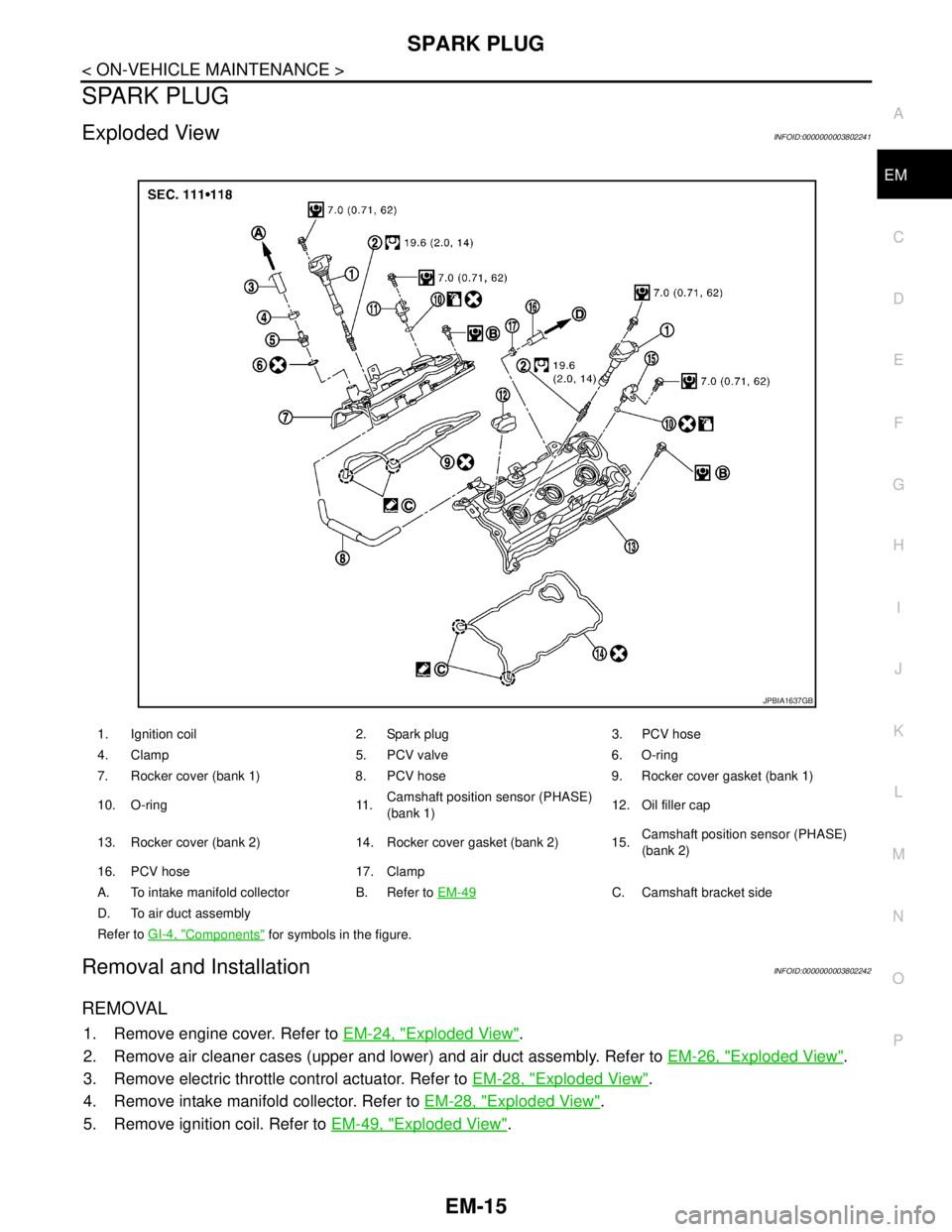
Exploded ViewINFOID:0000000003802241
Removal and InstallationINFOID:0000000003802242
REMOVAL
1. Remove engine cover. Refer to EM-24, "Exploded View".
2. Remove air cleaner cases (upper and lower) and air duct assembly. Refer to EM-26, "
Exploded View".
3. Remove electric throttle control actuator. Refer to EM-28, "
Exploded View".
4. Remove intake manifold collector. Refer to EM-28, "
Exploded View".
5. Remove ignition coil. Refer to EM-49, "
Exploded View".
1. Ignition coil 2. Spark plug 3. PCV hose
4. Clamp 5. PCV valve 6. O-ring
7. Rocker cover (bank 1) 8. PCV hose 9. Rocker cover gasket (bank 1)
10. O-ring 11.Camshaft position sensor (PHASE)
(bank 1)12. Oil filler cap
13. Rocker cover (bank 2) 14. Rocker cover gasket (bank 2) 15.Camshaft position sensor (PHASE)
(bank 2)
16. PCV hose 17. Clamp
A. To intake manifold collector B. Refer to EM-49
C. Camshaft bracket side
D. To air duct assembly
Refer to GI-4, "
Components" for symbols in the figure.
JPBIA1637GB
Page 1901 of 5121
EM-26
< ON-VEHICLE REPAIR >
AIR CLEANER AND AIR DUCT
AIR CLEANER AND AIR DUCT
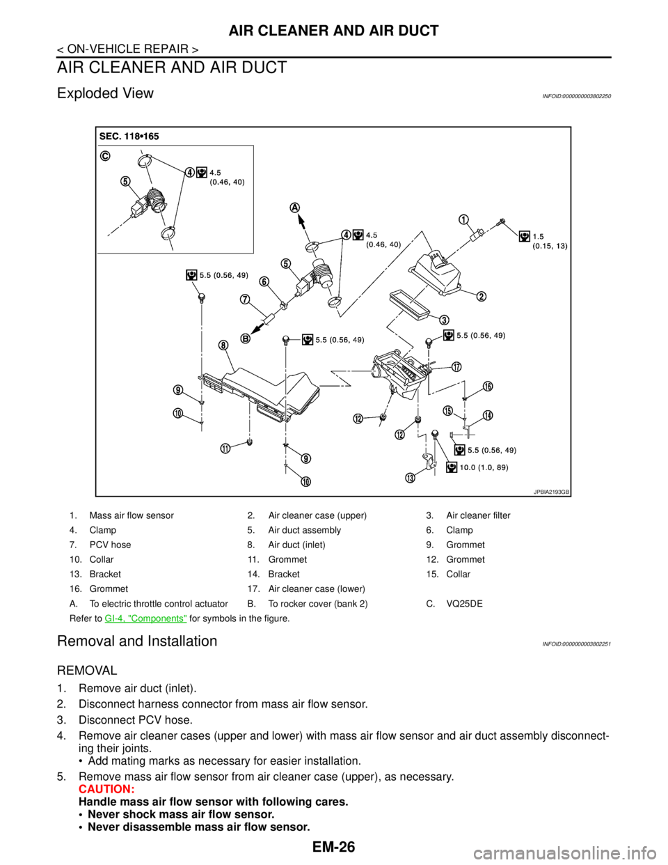
Exploded ViewINFOID:0000000003802250
Removal and InstallationINFOID:0000000003802251
REMOVAL
1. Remove air duct (inlet).
2. Disconnect harness connector from mass air flow sensor.
3. Disconnect PCV hose.
4. Remove air cleaner cases (upper and lower) with mass air flow sensor and air duct assembly disconnect-
ing their joints.
Add mating marks as necessary for easier installation.
5. Remove mass air flow sensor from air cleaner case (upper), as necessary.
CAUTION:
Handle mass air flow sensor with following cares.
Never shock mass air flow sensor.
Never disassemble mass air flow sensor.
1. Mass air flow sensor 2. Air cleaner case (upper) 3. Air cleaner filter
4. Clamp 5. Air duct assembly 6. Clamp
7. PCV hose 8. Air duct (inlet) 9. Grommet
10. Collar 11. Grommet 12. Grommet
13. Bracket 14. Bracket 15. Collar
16. Grommet 17. Air cleaner case (lower)
A. To electric throttle control actuator B. To rocker cover (bank 2) C. VQ25DE
Refer to GI-4, "
Components" for symbols in the figure.
JPBIA2193GB
Page 1902 of 5121
AIR CLEANER AND AIR DUCT
EM-27
< ON-VEHICLE REPAIR >
C
D
E
F
G
H
I
J
K
L
MA
EM
N
P O
Never touch mass air flow sensor.
INSTALLATION
Note the following, and install in the reverse order of removal.
Align marks. Attach each joint. Screw clamps firmly.
InspectionINFOID:0000000003802252
INSPECTION AFTER REMOVAL
Inspect air duct assembly for crack or tear.
If anything found, replace air duct assembly.
Page 1905 of 5121

EM-30
< ON-VEHICLE REPAIR >
INTAKE MANIFOLD COLLECTOR
2. Remove air cleaner cases (upper and lower) with mass air flow sensor and air duct assembly. Refer to
EM-26, "
Exploded View".
3. Drain engine coolant, or when water hoses are disconnected, attach plug to prevent engine coolant leak-
age. Refer to CO-8, "
Draining".
CAUTION:
Perform this step when the engine is cold.
4. Remove front wiper arm and extension cowl top. Refer to WW-105, "
Exploded View" and EXT-20,
"Exploded View".
5. Disconnect water hoses from electric throttle control actuator.
When engine coolant is not drained from radiator, attach plug to water hoses to prevent engine coolant
leakage.
6. Remove electric throttle control actuator as follows:
a. Disconnect harness connector.
b. Loosen mounting bolts in reverse order as shown in the figure.
CAUTION:
Handle carefully to avoid any shock to electric throttle
control actuator.
Never disassemble.
7. Remove the following parts:
Vacuum hose
PCV hose
High pressure piping from intake manifold collector: Refer to ST-34, "
Exploded View".
Electronic controlled engine mount control solenoid valve
8. Disconnect EVAP hoses and harness connector from EVAP canister purge control solenoid valve.
9. Remove EVAP canister purge control solenoid valve and bracket assembly.
10. Remove VIAS control solenoid valve mounting bolts and vacuum gallery mounting bolts, and then move
vacuum gallery.
Add mating marks as necessary for easier installation.
11. Loosen mounting nuts and bolts in reverse order as shown in
the figure, and remove intake manifold collector and gasket.
CAUTION:
Cover engine openings to avoid entry of foreign materials.
NOTE:
Figure is shown as an example of VQ35DE.
INSTALLATION
Note the following, and install in the reverse order of removal.
Intake Manifold Collector
JPBIA1631ZZ
: Engine front
JPBIA1628ZZ
Page 1909 of 5121
EM-34
< ON-VEHICLE REPAIR >
EXHAUST MANIFOLD AND THREE WAY CATALYST
EXHAUST MANIFOLD AND THREE WAY CATALYST
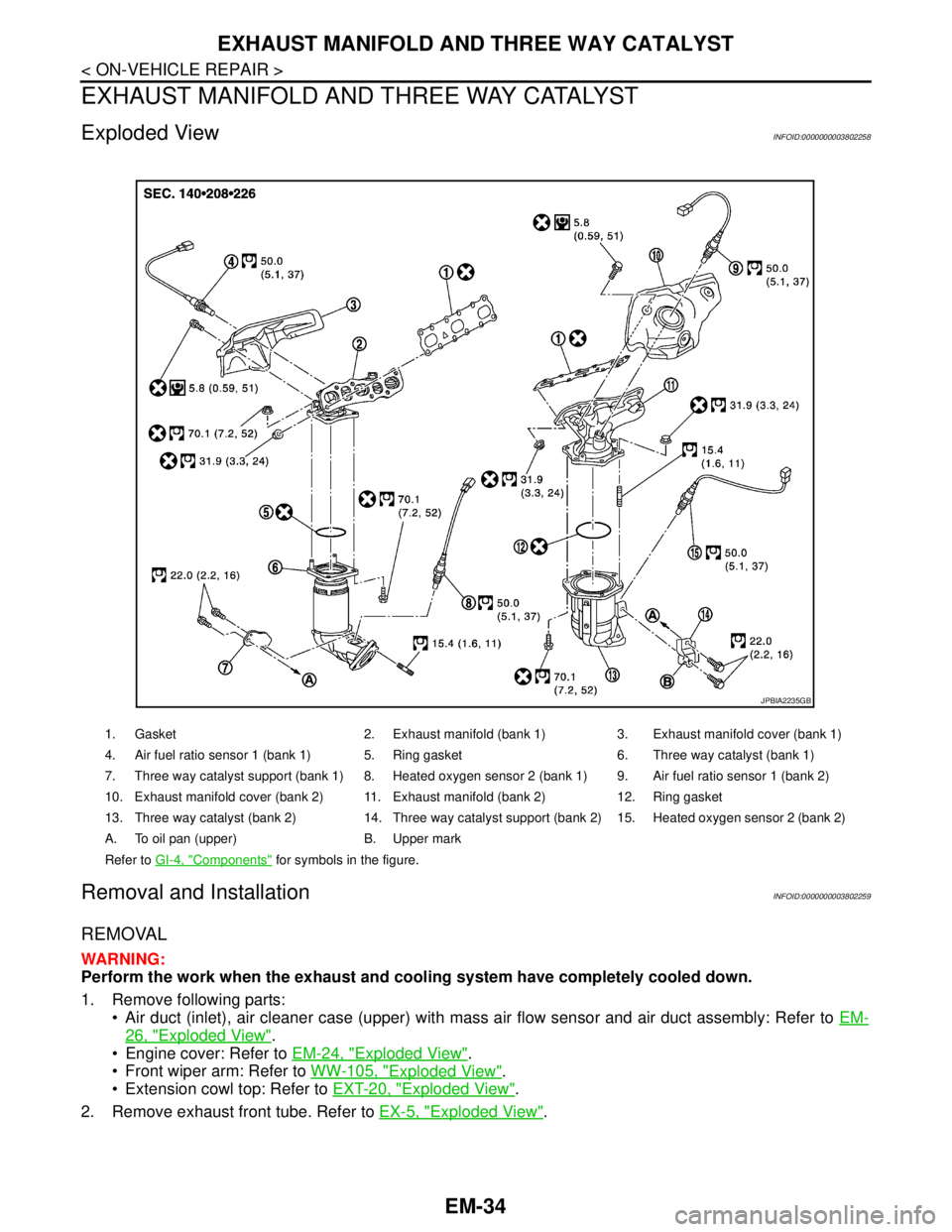
Exploded ViewINFOID:0000000003802258
Removal and InstallationINFOID:0000000003802259
REMOVAL
WARNING:
Perform the work when the exhaust and cooling system have completely cooled down.
1. Remove following parts:
Air duct (inlet), air cleaner case (upper) with mass air flow sensor and air duct assembly: Refer to EM-
26, "Exploded View".
Engine cover: Refer to EM-24, "
Exploded View".
Front wiper arm: Refer to WW-105, "
Exploded View".
Extension cowl top: Refer to EXT-20, "
Exploded View".
2. Remove exhaust front tube. Refer to EX-5, "
Exploded View".
1. Gasket 2. Exhaust manifold (bank 1) 3. Exhaust manifold cover (bank 1)
4. Air fuel ratio sensor 1 (bank 1) 5. Ring gasket 6. Three way catalyst (bank 1)
7. Three way catalyst support (bank 1) 8. Heated oxygen sensor 2 (bank 1) 9. Air fuel ratio sensor 1 (bank 2)
10. Exhaust manifold cover (bank 2) 11. Exhaust manifold (bank 2) 12. Ring gasket
13. Three way catalyst (bank 2) 14. Three way catalyst support (bank 2) 15. Heated oxygen sensor 2 (bank 2)
A. To oil pan (upper) B. Upper mark
Refer to GI-4, "
Components" for symbols in the figure.
JPBIA2235GB
Page 1910 of 5121
EXHAUST MANIFOLD AND THREE WAY CATALYST
EM-35
< ON-VEHICLE REPAIR >
C
D
E
F
G
H
I
J
K
L
MA
EM
N
P O
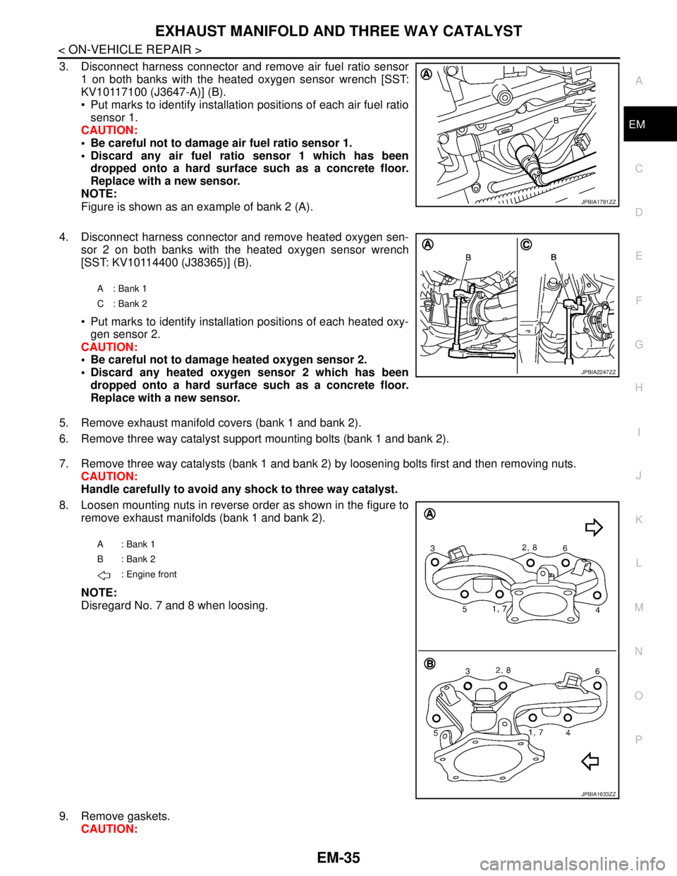
3. Disconnect harness connector and remove air fuel ratio sensor
1 on both banks with the heated oxygen sensor wrench [SST:
KV10117100 (J3647-A)] (B).
Put marks to identify installation positions of each air fuel ratio
sensor 1.
CAUTION:
Be careful not to damage air fuel ratio sensor 1.
Discard any air fuel ratio sensor 1 which has been
dropped onto a hard surface such as a concrete floor.
Replace with a new sensor.
NOTE:
Figure is shown as an example of bank 2 (A).
4. Disconnect harness connector and remove heated oxygen sen-
sor 2 on both banks with the heated oxygen sensor wrench
[SST: KV10114400 (J38365)] (B).
Put marks to identify installation positions of each heated oxy-
gen sensor 2.
CAUTION:
Be careful not to damage heated oxygen sensor 2.
Discard any heated oxygen sensor 2 which has been
dropped onto a hard surface such as a concrete floor.
Replace with a new sensor.
5. Remove exhaust manifold covers (bank 1 and bank 2).
6. Remove three way catalyst support mounting bolts (bank 1 and bank 2).
7. Remove three way catalysts (bank 1 and bank 2) by loosening bolts first and then removing nuts.
CAUTION:
Handle carefully to avoid any shock to three way catalyst.
8. Loosen mounting nuts in reverse order as shown in the figure to
remove exhaust manifolds (bank 1 and bank 2).
NOTE:
Disregard No. 7 and 8 when loosing.
9. Remove gaskets.
CAUTION:
JPBIA1781ZZ
A : Bank 1
C : Bank 2
JPBIA2247ZZ
A: Bank 1
B: Bank 2
: Engine front
JPBIA1633ZZ
Page 1911 of 5121
EM-36
< ON-VEHICLE REPAIR >
EXHAUST MANIFOLD AND THREE WAY CATALYST
Cover engine openings to avoid entry of foreign materials.
INSTALLATION
Note the following, and install in the reverse order of removal.
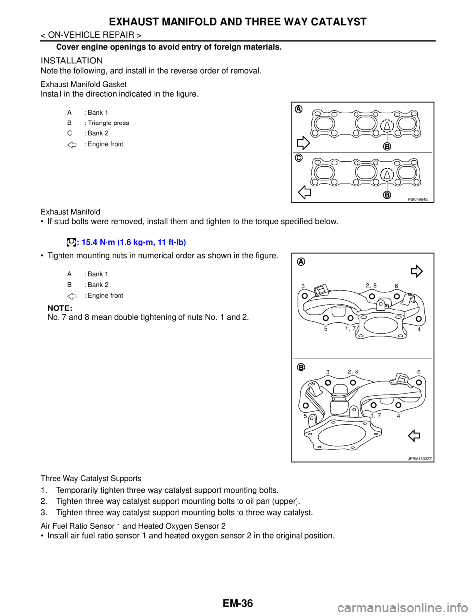
Exhaust Manifold Gasket
Install in the direction indicated in the figure.
Exhaust Manifold
If stud bolts were removed, install them and tighten to the torque specified below.
Tighten mounting nuts in numerical order as shown in the figure.
NOTE:
No. 7 and 8 mean double tightening of nuts No. 1 and 2.
Three Way Catalyst Supports
1. Temporarily tighten three way catalyst support mounting bolts.
2. Tighten three way catalyst support mounting bolts to oil pan (upper).
3. Tighten three way catalyst support mounting bolts to three way catalyst.
Air Fuel Ratio Sensor 1 and Heated Oxygen Sensor 2
Install air fuel ratio sensor 1 and heated oxygen sensor 2 in the original position.
A: Bank 1
B : Triangle press
C: Bank 2
: Engine front
PBIC4954E
: 15.4 N·m (1.6 kg-m, 11 ft-lb)
A: Bank 1
B: Bank 2
: Engine front
JPBIA1633ZZ
Page 1912 of 5121
EXHAUST MANIFOLD AND THREE WAY CATALYST
EM-37
< ON-VEHICLE REPAIR >
C
D
E
F
G
H
I
J
K
L
MA
EM
N
P O
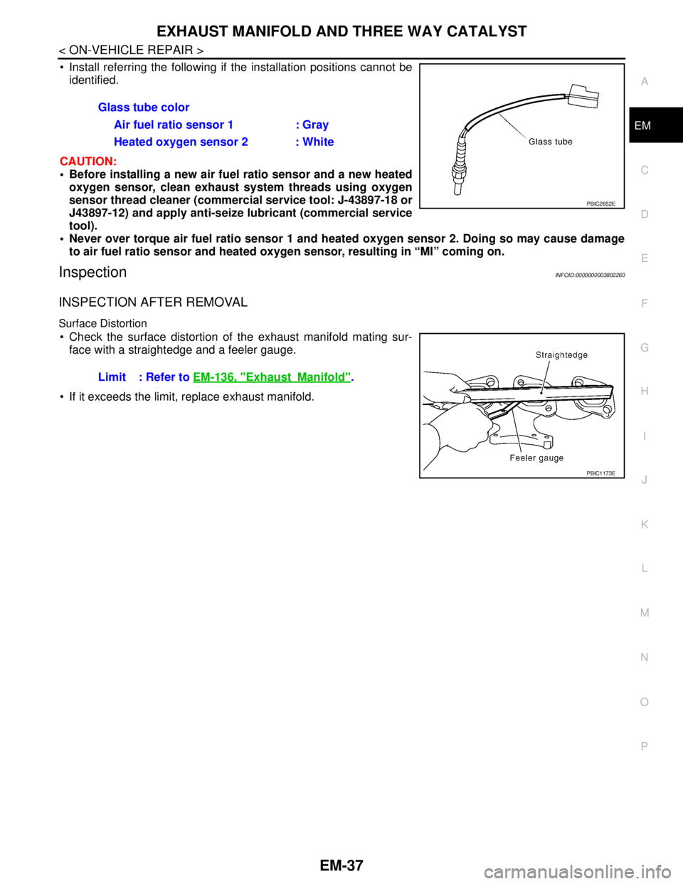
Install referring the following if the installation positions cannot be
identified.
CAUTION:
Before installing a new air fuel ratio sensor and a new heated
oxygen sensor, clean exhaust system threads using oxygen
sensor thread cleaner (commercial service tool: J-43897-18 or
J43897-12) and apply anti-seize lubricant (commercial service
tool).
Never over torque air fuel ratio sensor 1 and heated oxygen sensor 2. Doing so may cause damage
to air fuel ratio sensor and heated oxygen sensor, resulting in “MI” coming on.
InspectionINFOID:0000000003802260
INSPECTION AFTER REMOVAL
Surface Distortion
Check the surface distortion of the exhaust manifold mating sur-
face with a straightedge and a feeler gauge.
If it exceeds the limit, replace exhaust manifold.Glass tube color
Air fuel ratio sensor 1 : Gray
Heated oxygen sensor 2 : White
PBIC2652E
Limit : Refer to EM-136, "ExhaustManifold".
PBIC1173E