2008 NISSAN TEANA tow
[x] Cancel search: towPage 3230 of 5121
MA-42
< ON-VEHICLE MAINTENANCE >
BODY MAINTENANCE
BODY MAINTENANCE
LOCKS, HINGES AND HOOD LATCH
LOCKS, HINGES AND HOOD LATCH : LubricatingINFOID:0000000003858318
For hood and hood lock illustration.
Hood: Refer to DLK-191, "
HOOD ASSEMBLY : Exploded View".
Hood lock control: Refer to DLK-220, "
Exploded View".
For door and door lock illustration.
Front door: Refer to DLK-201, "
DOOR ASSEMBLY : Exploded View".
Front door lock: Refer to DLK-222, "
DOOR LOCK : Exploded View".
Rear door: Refer to DLK-207, "
DOOR ASSEMBLY : Exploded View".
Rear door lock: Refer to DLK-227, "
DOOR LOCK : Exploded View".
For trunk lid and trunk lid lock illustration.
Trunk lid: Refer to DLK-213, "
TRUNK LID ASSEMBLY : Exploded View".
Trunk lid lock: Refer to DLK-231, "
Exploded View".
SEAT BELT, BUCKLES, RETRACTORS, ANCHORS AND ADJUSTERS
SEAT BELT, BUCKLES, RETRACTORS, ANCHORS AND ADJUSTERS : Inspection
INFOID:0000000003858319
For front seat belt illustration. Refer to SB-5, "SEAT BELT RETRACTOR : Exploded View".
For rear seat belt illustration. Refer to SB-10, "
SEAT BELT RETRACTOR : Exploded View".
CAUTION:
After any collision, inspect all seat belt assemblies, including retractors and other attached hard-
wares (I.e. anchor bolt, guide rail set). Nissan recommends to replace all seat belt assemblies in use
during a collision, unless not damaged and properly operating after minor collision.
Also inspect seat belt assemblies not in use during a collision, and replace if damaged or improperly
operating.
Seat belt pre-tensioner should be replaced even if the seat belts are not in use during a frontal colli-
sion where the driver and passenger air bags are deployed.
If any component of seat belt assembly is questionable, do not repair.
Replace as seat belt assembly.
If webbing is cut, frayed, or damaged, replace belt assembly.
Never oil tongue and buckle.
Use a genuine NISSAN seat belt assembly.
For details, refer to SB-3, "
SEAT BELT RETRACTOR : Inspection" , SB-8, "SEAT BELT RETRACTOR :
Inspection" in SB section.
Check anchors for loose mounting
Check belts for damage
Check retractor for smooth operation
Check function of buckles and tongues when buckled and released
BODY CORROSION
BODY CORROSION : Checking Body CorrosionINFOID:0000000003858320
Visually check body panels for collision damage (scratches, chipping, rubbing, etc.) or damage to the anti-cor-
rosion materials. In particular, check the following locations.
HEMMED PANELS
Hood front end, door lower end, trunk lid rear end, etc.
PA N E L J O I N T
Side sill of rear fender and center pillar, rear wheel housing of rear fender, around strut tower in engine com-
partment, etc.
PA N E L E D G E
Trunk lid opening, sunroof opening, fender wheel-arch flange, fuel filler lid flange, around holes in panel, etc.
PARTS CONTACT
Waist moulding, windshield moulding, bumper, etc.
Page 3831 of 5121
RF-100
< ON-VEHICLE REPAIR >
SUNSHADE
Remove it to the lower part while pushing the front sunshade (1)
and rear sunshade (2) towards the direction of the arrow in the
figure.
INSTALLATION
Install in the reverse order of removal.
CAUTION:
Be careful not to release the spring when installing the sunshade.
JMKIA2515ZZ
Page 4217 of 5121
PRECAUTIONS
SR-3
< PRECAUTION >
C
D
E
F
G
I
J
K
L
MA
B
SR
N
O
P
Diagnosis sensor unit must always be installed with their arrow marks “⇐” pointing towards the front of the
vehicle for proper operation. Also check diagnosis sensor unit for cracks, deformities or rust before installa-
tion and replace as required.
The spiral cable must be aligned in the neutral position since its rotations are limited. Do not turn steering
wheel and column after removal of steering gear.
Handle air bag module carefully. Always place driver and front passenger air bag modules with the pad side
facing upward and seat mounted front side air bag module standing with the stud bolt side facing down.
Conduct self-diagnosis to check entire SRS for proper functioning after replacing any components.
After air bag inflates, the front instrument panel assembly should be replaced if damaged.
Always replace instrument panel pad following front passenger air bag deployment.
Occupant Classification SystemINFOID:0000000003751422
Replace occupant classification system control unit and passenger front seat cushion as an assembly.
With VENTILATION SEAT: Refer to SE-89, "
Exploded View".
Without VENTILATION SEAT: Refer to SE-130, "
Exploded View".
Page 4390 of 5121
PRECAUTIONS
SRC-147
< PRECAUTION >
C
D
E
F
G
I
J
K
L
MA
B
SRC
N
O
P
PRECAUTION
PRECAUTIONS
Precaution for Supplemental Restraint System (SRS) "AIR BAG" and "SEAT BELT
PRE-TENSIONER"
INFOID:0000000003814141
The Supplemental Restraint System such as “AIR BAG” and “SEAT BELT PRE-TENSIONER”, used along
with a front seat belt, helps to reduce the risk or severity of injury to the driver and front passenger for certain
types of collision. Information necessary to service the system safely is included in the “SRS AIRBAG” and
“SEAT BELT” of this Service Manual.
WARNING:
To avoid rendering the SRS inoperative, which could increase the risk of personal injury or death in
the event of a collision which would result in air bag inflation, all maintenance must be performed by
an authorized NISSAN/INFINITI dealer.
Improper maintenance, including incorrect removal and installation of the SRS, can lead to personal
injury caused by unintentional activation of the system. For removal of Spiral Cable and Air Bag
Module, see the “SRS AIRBAG”.
Never use electrical test equipment on any circuit related to the SRS unless instructed to in this Ser-
vice Manual. SRS wiring harnesses can be identified by yellow and/or orange harnesses or harness
connectors.
ServiceINFOID:0000000003814109
Do not use electrical test equipment to check SRS circuits unless instructed to in this Service Manual.
Before servicing the SRS, turn ignition switch OFF, disconnect battery negative terminal and wait at least 3
minutes.
For approximately 3 minutes after the battery negative terminal is removed, it is still possible for the air bag
and seat belt pre-tensioner to deploy. Therefore, do not work on any SRS connectors or wires until at least 3
minutes have elapsed.
Diagnosis sensor unit must always be installed with their arrow marks “⇐” pointing towards the front of the
vehicle for proper operation. Also check diagnosis sensor unit for cracks, deformities or rust before installa-
tion and replace as required.
The spiral cable must be aligned in the neutral position since its rotations are limited. Do not turn steering
wheel and column after removal of steering gear.
Handle air bag module carefully. Always place driver and front passenger air bag modules with the pad side
facing upward and seat mounted front side air bag module standing with the stud bolt side facing down.
Conduct self-diagnosis to check entire SRS for proper function after replacing any components.
After air bag inflates, the front instrument panel assembly should be replaced if damaged.
Always replace instrument panel pad following front passenger air bag deployment.
Page 4394 of 5121

ST-4
< PRECAUTION >
PRECAUTIONS
- For easier and proper assembly, place disassembled parts in order on a parts rack.
- Use nylon cloth or paper towels to clean the parts; common shop rags can leave lint that might inter-
fere with their operation.
- Never reuse non-reusable parts.
- Before assembling, apply the specified grease to the directed parts.
Page 4416 of 5121
ST-26
< ON-VEHICLE REPAIR >
STEERING GEAR AND LINKAGE
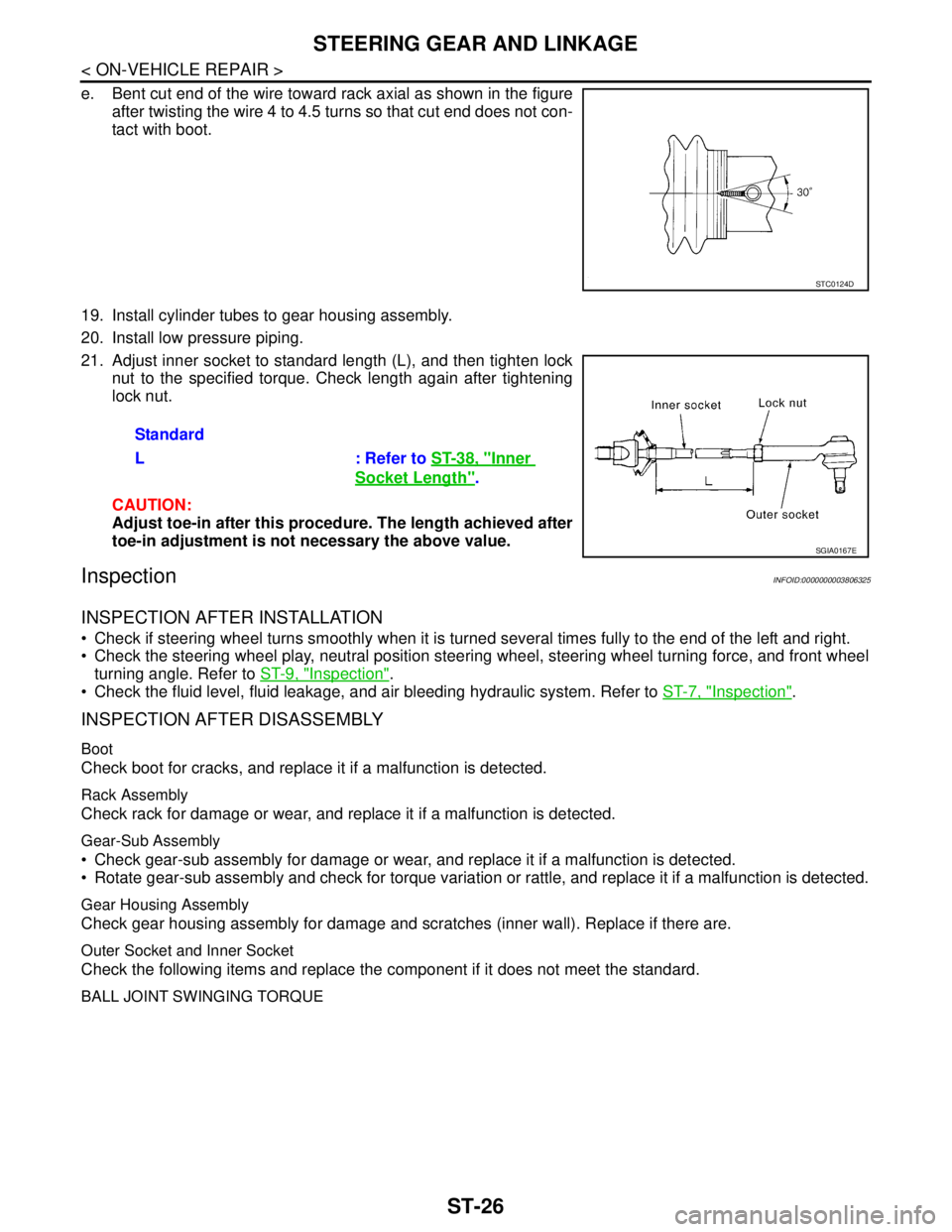
e. Bent cut end of the wire toward rack axial as shown in the figure
after twisting the wire 4 to 4.5 turns so that cut end does not con-
tact with boot.
19. Install cylinder tubes to gear housing assembly.
20. Install low pressure piping.
21. Adjust inner socket to standard length (L), and then tighten lock
nut to the specified torque. Check length again after tightening
lock nut.
CAUTION:
Adjust toe-in after this procedure. The length achieved after
toe-in adjustment is not necessary the above value.
InspectionINFOID:0000000003806325
INSPECTION AFTER INSTALLATION
Check if steering wheel turns smoothly when it is turned several times fully to the end of the left and right.
Check the steering wheel play, neutral position steering wheel, steering wheel turning force, and front wheel
turning angle. Refer to ST-9, "
Inspection".
Check the fluid level, fluid leakage, and air bleeding hydraulic system. Refer to ST-7, "
Inspection".
INSPECTION AFTER DISASSEMBLY
Boot
Check boot for cracks, and replace it if a malfunction is detected.
Rack Assembly
Check rack for damage or wear, and replace it if a malfunction is detected.
Gear-Sub Assembly
Check gear-sub assembly for damage or wear, and replace it if a malfunction is detected.
Rotate gear-sub assembly and check for torque variation or rattle, and replace it if a malfunction is detected.
Gear Housing Assembly
Check gear housing assembly for damage and scratches (inner wall). Replace if there are.
Outer Socket and Inner Socket
Check the following items and replace the component if it does not meet the standard.
BALL JOINT SWINGING TORQUE
STC0124D
Standard
L : Refer to ST-38, "
Inner
Socket Length".
SGIA0167E
Page 4625 of 5121
![NISSAN TEANA 2008 Service Manual TM-152
< ON-VEHICLE MAINTENANCE >[CVT: RE0F09B]
CVT POSITION
CVT POSITION
Inspection and AdjustmentINFOID:0000000003849084
INSPECTION
1. Move selector lever to “P” position, and turn ignition swit NISSAN TEANA 2008 Service Manual TM-152
< ON-VEHICLE MAINTENANCE >[CVT: RE0F09B]
CVT POSITION
CVT POSITION
Inspection and AdjustmentINFOID:0000000003849084
INSPECTION
1. Move selector lever to “P” position, and turn ignition swit](/manual-img/5/57391/w960_57391-4624.png)
TM-152
< ON-VEHICLE MAINTENANCE >[CVT: RE0F09B]
CVT POSITION
CVT POSITION
Inspection and AdjustmentINFOID:0000000003849084
INSPECTION
1. Move selector lever to “P” position, and turn ignition switch ON (engine stop).
2. Check that selector lever can be shifted to other than “P” position when brake pedal is depressed. Also
check that selector lever can be shifted from “P” position only when brake pedal is depressed.
3. Move selector lever and check for excessive effort, sticking, noise or rattle.
4. Check that selector lever stops at each position with the feel of engagement when it is moved through all
the positions. Check that the actual position of selector lever matches the position shown by shift position
indicator and manual lever on the transaxle.
5. The method of operating selector lever to individual positions
correctly should be as shown.
6. When selector button is pressed in “P”, “R”, “N”, “D” or “L” posi-
tion without applying forward/backward force to selector lever,
check button operation for sticking.
7. Check that back-up lamps illuminate only when selector lever is
placed in the “R” position.
8. When in “R” position, check that back-up lamps illuminate even
when the selector lever is pushed toward the “P” position.
CAUTION:
Check the lighting without pressing shift button.
9. Check that back-up lamps do not illuminate when selector lever is pushed toward the “R” position when in
the “P” or “N” position.
CAUTION:
Check the lighting without pressing shift button.
10. Check that the engine can only be started with selector lever in the “P” and “N” positions.
11. Check that transaxle is locked completely in “P” position.
ADJUSTMENT
1. Move selector lever to “ P” position.
CAUTION:
Turn wheels more than 1/4 rotations and apply the park
lock.
2. Loosen the control cable nut (A).
3. Place manual lever (B) to “P” position.
CAUTION:
Never apply any force to manual lever.
4. Tighten the control cable nut. Refer to TM-157, "
Exploded View".
CAUTION:
Fix manual lever when tightening.
JPDIA0343GB
JPDIA0794ZZ
Page 4787 of 5121
![NISSAN TEANA 2008 Service Manual TM-314
< ON-VEHICLE MAINTENANCE >[CVT: RE0F10A]
CVT POSITION
CVT POSITION
Inspection and AdjustmentINFOID:0000000003806512
INSPECTION
1. Place selector lever in “P” position, and turn ignition swi NISSAN TEANA 2008 Service Manual TM-314
< ON-VEHICLE MAINTENANCE >[CVT: RE0F10A]
CVT POSITION
CVT POSITION
Inspection and AdjustmentINFOID:0000000003806512
INSPECTION
1. Place selector lever in “P” position, and turn ignition swi](/manual-img/5/57391/w960_57391-4786.png)
TM-314
< ON-VEHICLE MAINTENANCE >[CVT: RE0F10A]
CVT POSITION
CVT POSITION
Inspection and AdjustmentINFOID:0000000003806512
INSPECTION
1. Place selector lever in “P” position, and turn ignition switch ON (engine stop).
2. Check that selector lever can be shifted to other than “P” position when brake pedal is depressed. Also
check that selector lever can be shifted from “P” position only when brake pedal is depressed.
3. Move the selector lever and check for excessive effort, sticking, noise or rattle.
4. Check that selector lever stops at each position with the feel of engagement when it is moved through all
the positions. Check that the actual position of the selector lever matches the position shown by the shift
position indicator and the manual lever on the transaxle.
5. The method of operating the selector lever to individual posi-
tions correctly should be as shown.
6. When selector button is pressed in “P”, “R”, “N”, “D” or “L” posi-
tion without applying forward/backward force to selector lever,
check button operation for sticking.
7. Check that back-up lamps illuminate only when selector lever is
placed in the “R” position.
8. When in “R” position, check that back-up lamps illuminate even
when the selector lever is pushed toward the “P” position.
CAUTION:
Check the lighting without pressing shift button.
9. Check that the back-up lamps do not illuminate when selector lever is pushed toward the “R” position
when in the “P” or “N” position.
CAUTION:
Check the lighting without pressing shift button.
10. Check that the engine can only be started with the selector lever in the “P” and “N” positions.
11. Check that transaxle is locked completely in “P” position.
ADJUSTMENT
1. Place selector lever in “ P” position.
CAUTION:
Turn wheels more than 1/4 rotations and apply the park lock.
2. Loosen nut (A) and place manual lever (B) in “P” position.
CAUTION:
Never apply any force to the manual lever.
3. Tighten nut. Refer to TM-319, "
Exploded View".
CAUTION:
Fix the manual lever when tightening.
JPDIA0343GB
JPDIA0780ZZ