2008 NISSAN TEANA tow
[x] Cancel search: towPage 3064 of 5121
IP-24
< ON-VEHICLE REPAIR >
CENTER CONSOLE ASSEMBLY
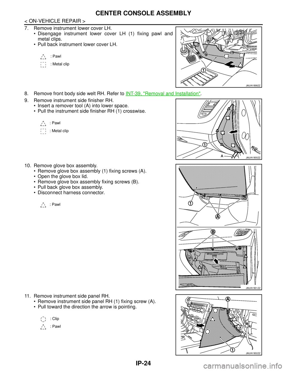
7. Remove instrument lower cover LH.
Disengage instrument lower cover LH (1) fixing pawl and
metal clips.
Pull back instrument lower cover LH.
8. Remove front body side welt RH. Refer to INT-39, "
Removal and Installation".
9. Remove instrument side finisher RH.
Insert a remover tool (A) into lower space.
Pull the instrument side finisher RH (1) crosswise.
10. Remove glove box assembly.
Remove glove box assembly (1) fixing screws (A).
Open the glove box lid.
Remove glove box assembly fixing screws (B).
Pull back glove box assembly.
Disconnect harness connector.
11. Remove instrument side panel RH.
Remove instrument side panel RH (1) fixing screw (A).
Pull toward the direction the arrow is pointing.
: Pawl
: Metal clip
JMJIA1898ZZ
: Pawl
: Metal clip
JMJIA1900ZZ
: Pawl
JMJIA1901ZZ
: Clip
: Pawl
JMJIA1902ZZ
Page 3195 of 5121
PERIODIC MAINTENANCE
MA-7
< ON-VEHICLE MAINTENANCE >
C
D
E
F
G
H
I
J
K
L
MB
MAN
OA
(5) Replace spark plug when the spark plug gap exceeds 1.4 mm (0.055 in) even if within specified periodic replacement
mileage.
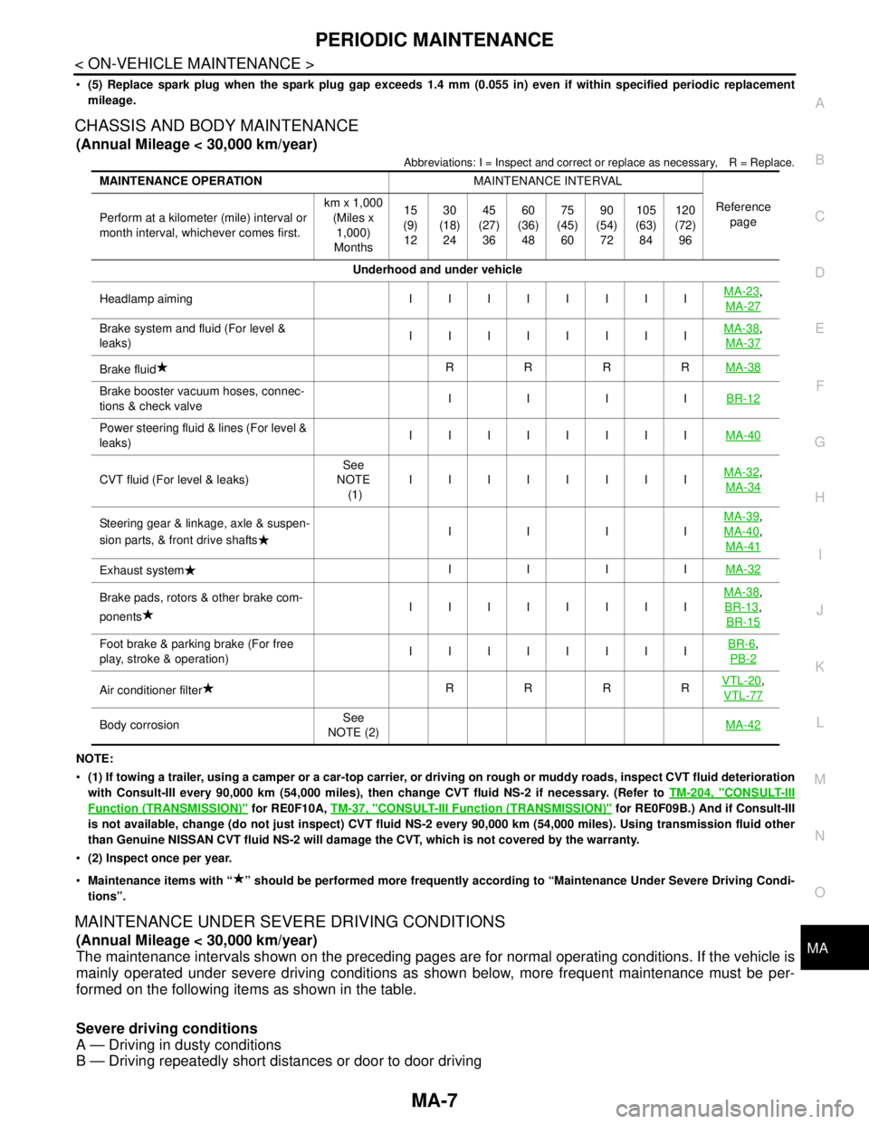
CHASSIS AND BODY MAINTENANCE
(Annual Mileage < 30,000 km/year)
Abbreviations: I = Inspect and correct or replace as necessary, R = Replace.
NOTE:
(1) If towing a trailer, using a camper or a car-top carrier, or driving on rough or muddy roads, inspect CVT fluid deterioration
with Consult-III every 90,000 km (54,000 miles), then change CVT fluid NS-2 if necessary. (Refer to TM-204, "
CONSULT-III
Function (TRANSMISSION)" for RE0F10A, TM-37, "CONSULT-III Function (TRANSMISSION)" for RE0F09B.) And if Consult-III
is not available, change (do not just inspect) CVT fluid NS-2 every 90,000 km (54,000 miles). Using transmission fluid other
than Genuine NISSAN CVT fluid NS-2 will damage the CVT, which is not covered by the warranty.
(2) Inspect once per year.
Maintenance items with “ ” should be performed more frequently according to “Maintenance Under Severe Driving Condi-
tions”.
MAINTENANCE UNDER SEVERE DRIVING CONDITIONS
(Annual Mileage < 30,000 km/year)
The maintenance intervals shown on the preceding pages are for normal operating conditions. If the vehicle is
mainly operated under severe driving conditions as shown below, more frequent maintenance must be per-
formed on the following items as shown in the table.
Severe driving conditions
A — Driving in dusty conditions
B — Driving repeatedly short distances or door to door driving
MAINTENANCE OPERATIONMAINTENANCE INTERVAL
Reference
page Perform at a kilometer (mile) interval or
month interval, whichever comes first.km x 1,000
(Miles x
1,000)
Months15
(9)
1230
(18)
2445
(27)
3660
(36)
4875
(45)
6090
(54)
72105
(63)
84120
(72)
96
Underhood and under vehicle
Headlamp aiming IIIIIIIIMA-23
,
MA-27
Brake system and fluid (For level &
leaks)IIIIIIIIMA-38,
MA-37
Brake fluidRRRRMA-38
Brake booster vacuum hoses, connec-
tions & check valveIIIIBR-12
Power steering fluid & lines (For level &
leaks)IIIIIIIIMA-40
CVT fluid (For level & leaks)See
NOTE
(1)IIIIIIIIMA-32,
MA-34
Steering gear & linkage, axle & suspen-
sion parts, & front drive shaftsIIIIMA-39,
MA-40
,
MA-41
Exhaust systemIIIIMA-32
Brake pads, rotors & other brake com-
ponentsIIIIIIIIMA-38,
BR-13
,
BR-15
Foot brake & parking brake (For free
play, stroke & operation)IIIIIIIIBR-6,
PB-2
Air conditioner filterRRRRVTL-20,
VTL-77
Body corrosionSee
NOTE (2)MA-42
Page 3196 of 5121
MA-8
< ON-VEHICLE MAINTENANCE >
PERIODIC MAINTENANCE
C — Towing a trailer or caravan
D — Extensive idling or urban driving
E — Driving in extremely adverse weather conditions or in areas where ambient temperatures are either
extremely low or extremely high
F — Driving in high humidity areas or in mountainous areas
G — Driving in areas using salt or other corrosive materials
H — Driving on rough and/or muddy roads or in the desert
I — Driving with frequent use of braking or in mountainous areas
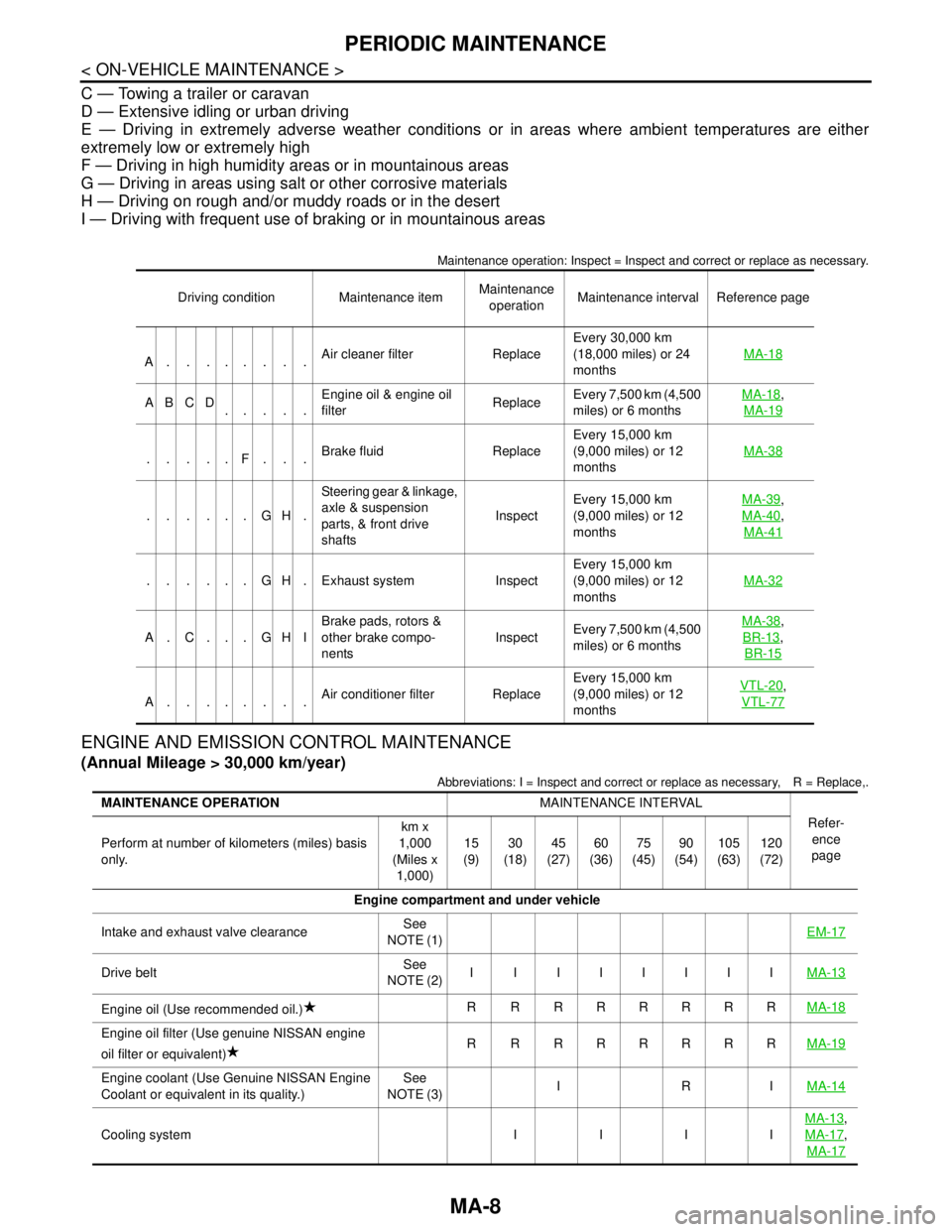
Maintenance operation: Inspect = Inspect and correct or replace as necessary.
ENGINE AND EMISSION CONTROL MAINTENANCE
(Annual Mileage > 30,000 km/year)
Abbreviations: I = Inspect and correct or replace as necessary, R = Replace,.
Driving condition Maintenance itemMaintenance
operationMaintenance interval Reference page
A........Air cleaner filter ReplaceEvery 30,000 km
(18,000 miles) or 24
monthsMA-18
ABCD
.....Engine oil & engine oil
filter ReplaceEvery 7,500 km (4,500
miles) or 6 monthsMA-18,
MA-19
.....F...Brake fluid ReplaceEvery 15,000 km
(9,000 miles) or 12
monthsMA-38
......GH.Steering gear & linkage,
axle & suspension
parts, & front drive
shafts InspectEvery 15,000 km
(9,000 miles) or 12
monthsMA-39
,
MA-40
,
MA-41
. . . . . . G H . Exhaust system InspectEvery 15,000 km
(9,000 miles) or 12
monthsMA-32
A. C. . . GHIBrake pads, rotors &
other brake compo-
nentsInspectEvery 7,500 km (4,500
miles) or 6 monthsMA-38
,
BR-13
,
BR-15
A........Air conditioner filter ReplaceEvery 15,000 km
(9,000 miles) or 12
monthsVTL-20
,
VTL-77
MAINTENANCE OPERATIONMAINTENANCE INTERVAL
Refer-
ence
page Perform at number of kilometers (miles) basis
only.km x
1,000
(Miles x
1,000)15
(9)30
(18)45
(27)60
(36)75
(45)90
(54)105
(63)120
(72)
Engine compartment and under vehicle
Intake and exhaust valve clearanceSee
NOTE (1)EM-17
Drive beltSee
NOTE (2)I I IIIIIIMA-13
Engine oil (Use recommended oil.)R RRRRRRRMA-18
Engine oil filter (Use genuine NISSAN engine
oil filter or equivalent)R RRRRRRRMA-19
Engine coolant (Use Genuine NISSAN Engine
Coolant or equivalent in its quality.)See
NOTE (3)IRIMA-14
Cooling system I I I IMA-13
,
MA-17
,
MA-17
Page 3198 of 5121
MA-10
< ON-VEHICLE MAINTENANCE >
PERIODIC MAINTENANCE
NOTE:
(1) If towing a trailer, using a camper or a car-top carrier, or driving on rough or muddy roads, inspect CVT fluid deterioration
with Consult-III every 90,000 km (54,000 miles), then change CVT fluid NS-2 if necessary. (Refer to TM-204, "
CONSULT-III
Function (TRANSMISSION)" for RE0F10A, TM-37, "CONSULT-III Function (TRANSMISSION)" for RE0F09B.) And if Consult-III
is not available, change (do not just inspect) CVT fluid NS-2 every 90,000 km (54,000 miles). Using transmission fluid other
than Genuine NISSAN CVT Fluid NS-2 will damage the CVT, which is not covered by the warranty.
(2) Inspect once per year.
Maintenance items with “ ” should be performed more frequently according to “Maintenance Under Severe Driving Condi-
tions”.
MAINTENANCE UNDER SEVERE DRIVING CONDITIONS
(Annual Mileage > 30,000 km/year)
The maintenance intervals shown on the preceding pages are for normal operating conditions. If the vehicle is
mainly operated under severe driving conditions as shown below, more frequent maintenance must be per-
formed on the following items as shown in the table.
Severe driving conditions
A — Driving in dusty conditions
B — Driving repeatedly short distances or door to door driving
C — Towing a trailer or caravan
D — Extensive idling or urban driving
E — Driving in extremely adverse weather conditions or in areas where ambient temperatures are either
extremely low or extremely high
F — Driving in high humidity areas or in mountainous areas
G — Driving in areas using salt or other corrosive materials
H — Driving on rough and/or muddy roads or in the desert
I — Driving with frequent use of braking or in mountainous areas
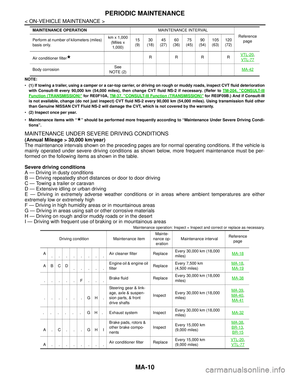
Maintenance operation: Inspect = Inspect and correct or replace as necessary.
Air conditioner filterRRRRVTL-20,
VTL-77
Body corrosionSee
NOTE (2)MA-42
MAINTENANCE OPERATIONMAINTENANCE INTERVAL
Reference
page Perform at number of kilometers (miles)
basis only.km x 1,000
(Miles x
1,000)15
(9)30
(18)45
(27)60
(36)75
(45)90
(54)105
(63)120
(72)
Driving condition Maintenance itemMainte-
nance op-
erationMaintenance intervalReference
page
A
........Air cleaner filter ReplaceEvery 30,000 km (18,000
miles) MA-18
ABCD
.....Engine oil & engine oil
filter ReplaceEvery 7,500 km
(4,500 miles) MA-18,
MA-19
.....F...Brake fluid ReplaceEvery 30,000 km (18,000
miles) MA-38
......GH.Steering gear & link-
age, axle & suspen-
sion parts, & front
drive shaftsInspectEvery 30,000 km (18,000
miles) MA-39
,
MA-40
,
MA-41
......GH.Exhaust system InspectEvery 30,000 km (18,000
miles)MA-32
A.C. . .GHIBrake pads, rotors &
other brake compo-
nentsInspectEvery 15,000 km
(9,000 miles) MA-38
,
BR-13
,
BR-15
A........Air conditioner filter ReplaceEvery 15,000 km
(9,000 miles) VTL-20
,
VTL-77
Page 3212 of 5121

MA-24
< ON-VEHICLE MAINTENANCE >
CHASSIS MAINTENANCE
HEADLAMP AIMING ADJUSTMENT (XENON TYPE) : Aiming Adjustment Procedure
(Low Beam)
INFOID:0000000003862421
1. Place the screen.
NOTE:
Stop the vehicle at the perpendicular angle to the wall.
Set the screen so that it is perpendicular to a level load surface.
2. Face the vehicle squarely toward the screen and make the distance between the headlamp center and
the screen 10 m (32.8 ft).
3. Start the engine and illuminate the headlamp (LO).
NOTE:
Block light from the headlamp that is not being adjusted with a thick fabric or another object, so that it
does not reach the adjustment screen.
CAUTION:
Do not cover lens surface with tape, etc. because it is made from plastic.
4. Use the aiming adjustment screw to adjust the elbow point projected by the low beams on the screen, so
that it is within the aiming adjustment area.
A. Headlamp (LO) RH
(UP/DOWN) adjustment screwB. Headlamp (HI) RH
(UP/DOWN) adjustment screwC. Headlamp (LO) RH
(UP-OUTSIDE/DOWN-INSIDE)
adjustment screw
D. Headlamp (HI) RH
(UP-INSIDE/DOWN-OUTSIDE)
adjustment screwE. Headlamp (LO) LH
(UP/DOWN) adjustment screwF. Headlamp (HI) LH
(UP/DOWN) adjustment screw
G. H e a d l a m p ( L O ) L H
(UP-OUTSIDE/DOWN-INSIDE)
adjustment screwH. Headlamp (HI) LH
(UP-INSIDE/DOWN-OUTSIDE)
adjustment screw
: Vehicle center
Adjustment screw Screw driver rotation Facing direction
AHeadlamp (LO) RH
(UP/DOWN)Clockwise UP
Counterclockwise DOWN
BHeadlamp (HI) RH
(UP/DOWN)Clockwise UP
Counterclockwise DOWN
CHeadlamp (LO) RH
(UP-OUTSIDE/DOWN-INSIDE)Clockwise DOWN-INSIDE
Counterclockwise UP-OUTSIDE
DHeadlamp (HI) RH
(UP-INSIDE/DOWN-OUTSIDE)Clockwise DOWN-OUTSIDE
Counterclockwise UP-INSIDE
EHeadlamp (LO) LH
(UP/DOWN)Clockwise UP
Counterclockwise DOWN
FHeadlamp (HI) LH
(UP/DOWN)Clockwise UP
Counterclockwise DOWN
GHeadlamp (LO) LH
(UP-OUTSIDE/DOWN-INSIDE)Clockwise DOWN-INSIDE
Counterclockwise UP-OUTSIDE
HHeadlamp (HI) LH
(UP-INSIDE/DOWN-OUTSIDE)Clockwise DOWN-OUTSIDE
Counterclockwise UP-INSIDE
Page 3214 of 5121
MA-26
< ON-VEHICLE MAINTENANCE >
CHASSIS MAINTENANCE
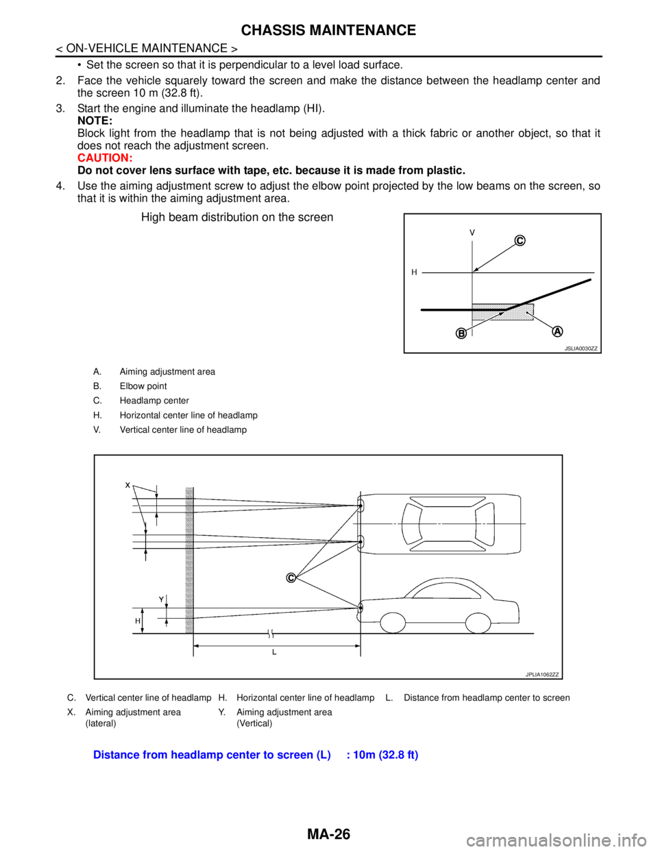
Set the screen so that it is perpendicular to a level load surface.
2. Face the vehicle squarely toward the screen and make the distance between the headlamp center and
the screen 10 m (32.8 ft).
3. Start the engine and illuminate the headlamp (HI).
NOTE:
Block light from the headlamp that is not being adjusted with a thick fabric or another object, so that it
does not reach the adjustment screen.
CAUTION:
Do not cover lens surface with tape, etc. because it is made from plastic.
4. Use the aiming adjustment screw to adjust the elbow point projected by the low beams on the screen, so
that it is within the aiming adjustment area.
High beam distribution on the screen
JSLIA0030ZZ
A. Aiming adjustment area
B. Elbow point
C. Headlamp center
H. Horizontal center line of headlamp
V. Vertical center line of headlamp
C. Vertical center line of headlamp H. Horizontal center line of headlamp L. Distance from headlamp center to screen
X. Aiming adjustment area
(lateral)Y. Aiming adjustment area
(Vertical)
Distance from headlamp center to screen (L) : 10m (32.8 ft)
JPLIA1062ZZ
Page 3217 of 5121
CHASSIS MAINTENANCE
MA-29
< ON-VEHICLE MAINTENANCE >
C
D
E
F
G
H
I
J
K
L
MB
MAN
OA
HEADLAMP AIMING ADJUSTMENT (HALOGEN TYPE) : Aiming Adjustment Proce-
dure (Low Beam)
INFOID:0000000003862424
1. Place the screen.
NOTE:
Stop the vehicle at the perpendicular angle to the wall.
Set the screen so that it is perpendicular to a level load surface.
2. Face the vehicle squarely toward the screen and make the distance between the headlamp center and
the screen 10 m (32.8 ft).
3. Start the engine and illuminate the headlamp (LO).
NOTE:
Block light from the headlamp that is not being adjusted with a thick fabric or another object, so that it
does not reach the adjustment screen.
CAUTION:
Do not cover lens surface with tape, etc. because it is made from plastic.
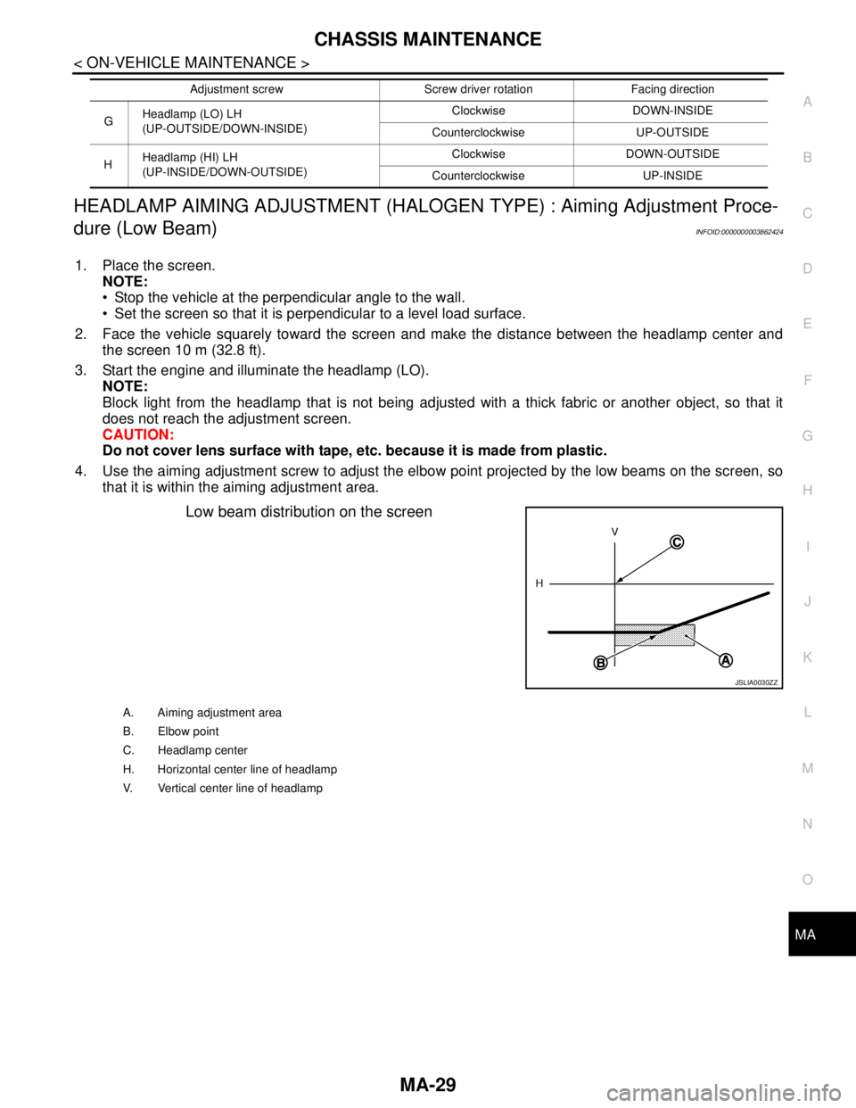
4. Use the aiming adjustment screw to adjust the elbow point projected by the low beams on the screen, so
that it is within the aiming adjustment area.
Low beam distribution on the screen
GHeadlamp (LO) LH
(UP-OUTSIDE/DOWN-INSIDE)Clockwise DOWN-INSIDE
Counterclockwise UP-OUTSIDE
HHeadlamp (HI) LH
(UP-INSIDE/DOWN-OUTSIDE)Clockwise DOWN-OUTSIDE
Counterclockwise UP-INSIDE Adjustment screw Screw driver rotation Facing direction
JSLIA0030ZZ
A. Aiming adjustment area
B. Elbow point
C. Headlamp center
H. Horizontal center line of headlamp
V. Vertical center line of headlamp
Page 3218 of 5121
MA-30
< ON-VEHICLE MAINTENANCE >
CHASSIS MAINTENANCE
Unit: mm (in)
HEADLAMP AIMING ADJUSTMENT (HALOGEN TYPE) : Aiming Adjustment Proce-
dure (High Beam)
INFOID:0000000003862425
1. Place the screen.
NOTE:
Stop the vehicle at the perpendicular angle to the wall.
Set the screen so that it is perpendicular to a level load surface.
2. Face the vehicle squarely toward the screen and make the distance between the headlamp center and
the screen 10 m (32.8 ft).
3. Start the engine and illuminate the headlamp (HI).
NOTE:
Block light from the headlamp that is not being adjusted with a thick fabric or another object, so that it
does not reach the adjustment screen.
CAUTION:
Do not cover lens surface with tape, etc. because it is made from plastic.
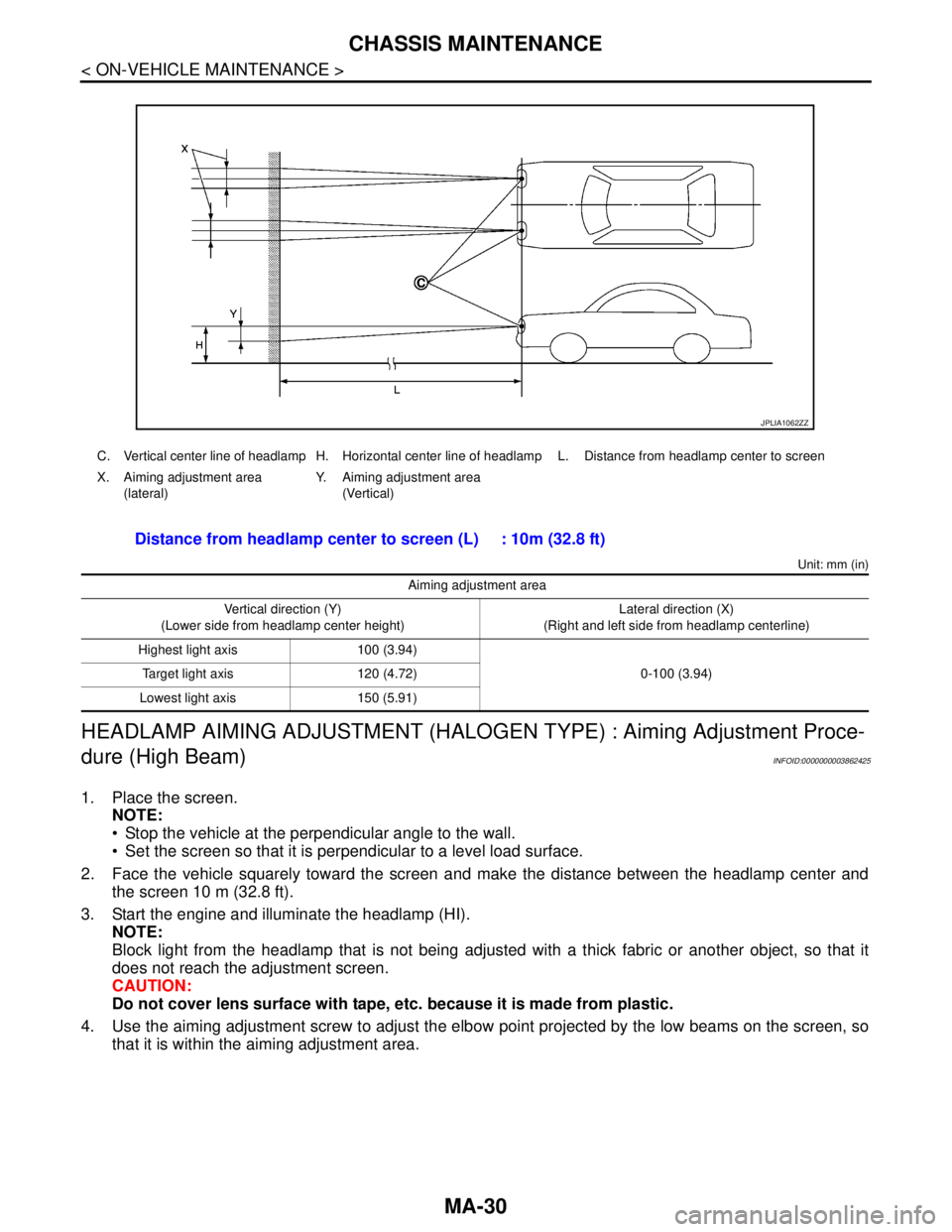
4. Use the aiming adjustment screw to adjust the elbow point projected by the low beams on the screen, so
that it is within the aiming adjustment area.
C. Vertical center line of headlamp H. Horizontal center line of headlamp L. Distance from headlamp center to screen
X. Aiming adjustment area
(lateral)Y. Aiming adjustment area
(Vertical)
Distance from headlamp center to screen (L) : 10m (32.8 ft)
Aiming adjustment area
Vertical direction (Y)
(Lower side from headlamp center height)Lateral direction (X)
(Right and left side from headlamp centerline)
Highest light axis 100 (3.94)
0-100 (3.94) Target light axis 120 (4.72)
Lowest light axis 150 (5.91)
JPLIA1062ZZ