2008 NISSAN TEANA tow
[x] Cancel search: towPage 2366 of 5121
![NISSAN TEANA 2008 Service Manual HEADLAMP AIMING ADJUSTMENT
EXL-337
< ON-VEHICLE MAINTENANCE >[HALOGEN TYPE]
C
D
E
F
G
H
I
J
K
MA
B
EXL
N
O
P
Aiming Adjustment Procedure (Low Beam)INFOID:0000000003829236
1. Place the screen.
NOTE:
NISSAN TEANA 2008 Service Manual HEADLAMP AIMING ADJUSTMENT
EXL-337
< ON-VEHICLE MAINTENANCE >[HALOGEN TYPE]
C
D
E
F
G
H
I
J
K
MA
B
EXL
N
O
P
Aiming Adjustment Procedure (Low Beam)INFOID:0000000003829236
1. Place the screen.
NOTE:
](/manual-img/5/57391/w960_57391-2365.png)
HEADLAMP AIMING ADJUSTMENT
EXL-337
< ON-VEHICLE MAINTENANCE >[HALOGEN TYPE]
C
D
E
F
G
H
I
J
K
MA
B
EXL
N
O
P
Aiming Adjustment Procedure (Low Beam)INFOID:0000000003829236
1. Place the screen.
NOTE:
Stop the vehicle at the perpendicular angle to the wall.
Set the screen so that it is perpendicular to a level load surface.
2. Face the vehicle squarely toward the screen and make the distance between the headlamp center and
the screen 10 m (32.8 ft).
3. Start the engine and illuminate the headlamp (LO).
NOTE:
Block light from the headlamp that is not being adjusted with a thick fabric or another object, so that it
does not reach the adjustment screen.
CAUTION:
Do not cover lens surface with tape, etc. because it is made from plastic.
4. Use the aiming adjustment screw to adjust the elbow point projected by the low beams on the screen, so
that it is within the aiming adjustment area.
A. Headlamp (LO) RH
(UP/DOWN) adjustment screwB. Headlamp (HI) RH
(UP/DOWN) adjustment screwC. Headlamp (LO) RH
(UP-OUTSIDE/DOWN-INSIDE)
adjustment screw
D. Headlamp (HI) RH
(UP-INSIDE/DOWN-OUTSIDE)
adjustment screwE. Headlamp (LO) LH
(UP/DOWN) adjustment screwF. Headlamp (HI) LH
(UP/DOWN) adjustment screw
G. H e a d l a m p ( L O ) L H
(UP-OUTSIDE/DOWN-INSIDE)
adjustment screwH. Headlamp (HI) LH
(UP-INSIDE/DOWN-OUTSIDE)
adjustment screw
: Vehicle center
Adjustment screw Screw driver rotation Facing direction
AHeadlamp (LO) RH
(UP/DOWN)Clockwise UP
Counterclockwise DOWN
BHeadlamp (HI) RH
(UP/DOWN)Clockwise UP
Counterclockwise DOWN
CHeadlamp (LO) RH
(UP-OUTSIDE/DOWN-INSIDE)Clockwise DOWN-INSIDE
Counterclockwise UP-OUTSIDE
DHeadlamp (HI) RH
(UP-INSIDE/DOWN-OUTSIDE)Clockwise DOWN-OUTSIDE
Counterclockwise UP-INSIDE
EHeadlamp (LO) LH
(UP/DOWN)Clockwise UP
Counterclockwise DOWN
FHeadlamp (HI) LH
(UP/DOWN)Clockwise UP
Counterclockwise DOWN
GHeadlamp (LO) LH
(UP-OUTSIDE/DOWN-INSIDE)Clockwise DOWN-INSIDE
Counterclockwise UP-OUTSIDE
HHeadlamp (HI) LH
(UP-INSIDE/DOWN-OUTSIDE)Clockwise DOWN-OUTSIDE
Counterclockwise UP-INSIDE
Page 2368 of 5121
![NISSAN TEANA 2008 Service Manual HEADLAMP AIMING ADJUSTMENT
EXL-339
< ON-VEHICLE MAINTENANCE >[HALOGEN TYPE]
C
D
E
F
G
H
I
J
K
MA
B
EXL
N
O
P
2. Face the vehicle squarely toward the screen and make the distance between the headlamp c NISSAN TEANA 2008 Service Manual HEADLAMP AIMING ADJUSTMENT
EXL-339
< ON-VEHICLE MAINTENANCE >[HALOGEN TYPE]
C
D
E
F
G
H
I
J
K
MA
B
EXL
N
O
P
2. Face the vehicle squarely toward the screen and make the distance between the headlamp c](/manual-img/5/57391/w960_57391-2367.png)
HEADLAMP AIMING ADJUSTMENT
EXL-339
< ON-VEHICLE MAINTENANCE >[HALOGEN TYPE]
C
D
E
F
G
H
I
J
K
MA
B
EXL
N
O
P
2. Face the vehicle squarely toward the screen and make the distance between the headlamp center and
the screen 10 m (32.8 ft).
3. Start the engine and illuminate the headlamp (HI).
NOTE:
Block light from the headlamp that is not being adjusted with a thick fabric or another object, so that it
does not reach the adjustment screen.
CAUTION:
Do not cover lens surface with tape, etc. because it is made from plastic.
4. Use the aiming adjustment screw to adjust the elbow point projected by the low beams on the screen, so
that it is within the aiming adjustment area.
High beam distribution on the screen
JSLIA0030ZZ
A. Aiming adjustment area
B. Elbow point
C. Headlamp center
H. Horizontal center line of headlamp
V. Vertical center line of headlamp
C. Vertical center line of headlamp H. Horizontal center line of headlamp L. Distance from headlamp center to screen
X. Aiming adjustment area
(lateral)Y. Aiming adjustment area
(Vertical)
Distance from headlamp center to screen (L) : 10m (32.8 ft)
JPLIA1062ZZ
Page 2383 of 5121
![NISSAN TEANA 2008 Service Manual EXL-354
< ON-VEHICLE REPAIR >[HALOGEN TYPE]
REAR COMBINATION LAMP
REAR COMBINATION LAMP
Exploded ViewINFOID:0000000003894373
REMOVAL
DISASSEMBLY
Removal and InstallationINFOID:0000000003894374
CAUTION NISSAN TEANA 2008 Service Manual EXL-354
< ON-VEHICLE REPAIR >[HALOGEN TYPE]
REAR COMBINATION LAMP
REAR COMBINATION LAMP
Exploded ViewINFOID:0000000003894373
REMOVAL
DISASSEMBLY
Removal and InstallationINFOID:0000000003894374
CAUTION](/manual-img/5/57391/w960_57391-2382.png)
EXL-354
< ON-VEHICLE REPAIR >[HALOGEN TYPE]
REAR COMBINATION LAMP
REAR COMBINATION LAMP
Exploded ViewINFOID:0000000003894373
REMOVAL
DISASSEMBLY
Removal and InstallationINFOID:0000000003894374
CAUTION:
Disconnect the battery negative terminal or remove the fuse.
REMOVAL
1. Remove the rear combination lamp finisher.
2. Remove the rear combination lamp mounting bolts.
3. Pull the rear combination lamp toward outside of the vehicle. And then remove the rear combination lamp.
4. Disconnect the rear combination lamp connector.
INSTALLATION
Install in the reverse order of removal.
1. Rear combination lamp 2. Rear combination lamp finisher
JPLIA1097ZZ
1. Back-up lamp bulb 2. Back-up lamp bulb socket 3. Rear turn signal lamp bulb socket
4. Rear turn signal lamp bulb
JPLIA1098ZZ
Page 2402 of 5121
FRONT BUMPER
EXT-13
< ON-VEHICLE REPAIR >
C
D
E
F
G
H
I
J
L
MA
B
EXT
N
O
P
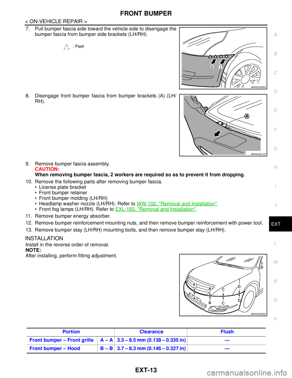
7. Pull bumper fascia side toward the vehicle side to disengage the
bumper fascia from bumper side brackets (LH/RH).
8. Disengage front bumper fascia from bumper brackets (A) (LH/
RH).
9. Remove bumper fascia assembly.
CAUTION:
When removing bumper fascia, 2 workers are required so as to prevent it from dropping.
10. Remove the following parts after removing bumper fascia.
License plate bracket
Front bumper retainer
Front bumper molding (LH/RH)
Headlamp washer nozzle (LH/RH). Refer to WW-102, "
Removal and Installation".
Front fog lamps (LH/RH). Refer to EXL-183, "
Removal and Installation".
11. Remove bumper energy absorber.
12. Remove bumper reinforcement mounting nuts, and then remove bumper reinforcement with power tool.
13. Remove bumper stay (LH/RH) mounting bolts, and then remove bumper stay (LH/RH).
INSTALLATION
Install in the reverse order of removal.
NOTE:
After installing, perform fitting adjustment.
: Pawl
JMKIA2520ZZ
JMKIA2521ZZ
JMKIA2550ZZ
Portion Clearance Flush
Front bumper – Front grille A – A 3.5 – 8.5 mm (0.138 – 0.335 in) —
Front bumper – Hood B – B 3.7 – 8.3 mm (0.146 – 0.327 in) —
Page 2406 of 5121
REAR BUMPER
EXT-17
< ON-VEHICLE REPAIR >
C
D
E
F
G
H
I
J
L
MA
B
EXT
N
O
P
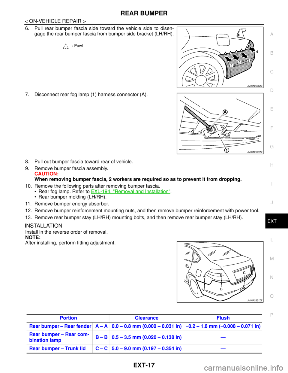
6. Pull rear bumper fascia side toward the vehicle side to disen-
gage the rear bumper fascia from bumper side bracket (LH/RH).
7. Disconnect rear fog lamp (1) harness connector (A).
8. Pull out bumper fascia toward rear of vehicle.
9. Remove bumper fascia assembly.
CAUTION:
When removing bumper fascia, 2 workers are required so as to prevent it from dropping.
10. Remove the following parts after removing bumper fascia.
Rear fog lamp. Refer to EXL-194, "
Removal and Installation".
Rear bumper molding (LH/RH).
11. Remove bumper energy absorber.
12. Remove bumper reinforcement mounting nuts, and then remove bumper reinforcement with power tool.
13. Remove rear bumper stay (LH/RH) mounting bolts, and then remove rear bumper stay (LH/RH).
INSTALLATION
Install in the reverse order of removal.
NOTE:
After installing, perform fitting adjustment.
: Pawl
JMKIA2526ZZ
JMKIA2527ZZ
JMKIA2551ZZ
Portion Clearance Flush
Rear bumper – Rear fender A – A 0.0 – 0.8 mm (0.000 – 0.031 in)−0.2 – 1.8 mm (−0.008 – 0.071 in)
Rear bumper – Rear com-
bination lampB – B 0.5 – 3.5 mm (0.020 – 0.138 in) —
Rear bumper – Trunk lid C – C 5.0 – 9.0 mm (0.197 – 0.354 in) —
Page 2407 of 5121
EXT-18
< ON-VEHICLE REPAIR >
FRONT GRILLE
FRONT GRILLE
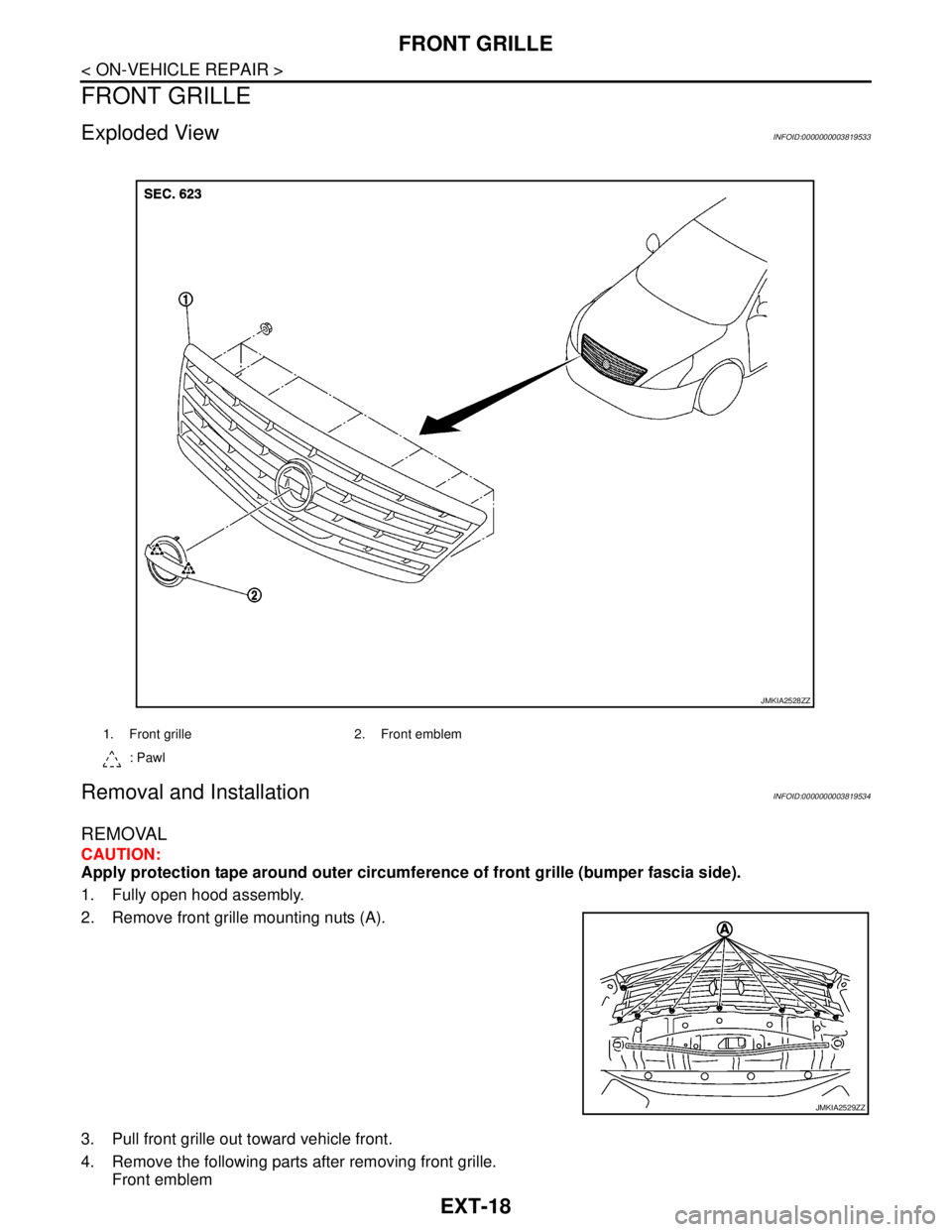
Exploded ViewINFOID:0000000003819533
Removal and InstallationINFOID:0000000003819534
REMOVAL
CAUTION:
Apply protection tape around outer circumference of front grille (bumper fascia side).
1. Fully open hood assembly.
2. Remove front grille mounting nuts (A).
3. Pull front grille out toward vehicle front.
4. Remove the following parts after removing front grille.
Front emblem
1. Front grille 2. Front emblem
: Pawl
JMKIA2528ZZ
JMKIA2529ZZ
Page 2494 of 5121
GI-1
GENERAL INFORMATION
C
D
E
F
G
H
I
J
K
L
MB
GI
SECTION GI
N
O
P
CONTENTS
GENERAL INFORMATION
HOW TO USE THIS MANUAL ......................3
HOW TO USE THIS MANUAL ............................3
Description ................................................................3
Terms ........................................................................3
Units ..........................................................................3
Contents ....................................................................3
Relation between Illustrations and Descriptions .......4
Components ..............................................................4
HOW TO FOLLOW TROUBLE DIAGNOSES .....6
Description ................................................................6
How to Follow Test Groups in Trouble Diagnosis ......6
Key to Symbols Signifying Measurements or Pro-
cedures .....................................................................
7
HOW TO READ WIRING DIAGRAMS ................9
Connector Symbols ...................................................9
Sample/Wiring Diagram -Example- .........................10
Description ..............................................................11
ABBREVIATIONS ..............................................13
Abbreviation List ......................................................13
TIGHTENING TORQUE OF STANDARD
BOLTS ................................................................
14
Description ..............................................................14
Tightening Torque Table (New Standard Includ-
ed) ...........................................................................
14
TERMINOLOGY .................................................17
SAE J1930 Terminology List ...................................17
FEATURES OF NEW MODEL .....................21
IDENTIFICATION INFORMATION .....................21
Model Variation .......................................................21
Information About Identification or Model Code ......21
Dimensions .............................................................23
Wheels & Tires ........................................................23
PRECAUTION ..............................................24
PRECAUTIONS .................................................24
Description ...............................................................24
Precaution for Supplemental Restraint System
(SRS) "AIR BAG" and "SEAT BELT PRE-TEN-
SIONER" .................................................................
24
Precautions For Xenon Headlamp Service .............24
Precaution Necessary for Steering Wheel Rota-
tion after Battery Disconnect ...................................
24
Precaution for Procedure without Cowl Top Cover ....25
General Precautions ................................................25
Three Way Catalyst .................................................27
Multiport Fuel Injection System or Engine Control
System .....................................................................
27
Hoses ......................................................................27
Engine Oils ..............................................................28
Air Conditioning .......................................................28
Fuel ..........................................................................29
LIFTING POINT .................................................30
Commercial Service Tools .......................................30
Garage Jack and Safety Stand and 2-Pole Lift .......30
Board-On Lift ...........................................................31
TOW TRUCK TOWING .....................................32
Tow Truck Towing ...................................................32
Vehicle Recovery (Freeing a Stuck Vehicle) ...........32
BASIC INSPECTION ...................................34
SERVICE INFORMATION FOR ELECTRICAL
INCIDENT ..........................................................
34
Work Flow ................................................................34
Control Units and Electrical Parts ............................34
Intermittent Incident .................................................35
Circuit Inspection .....................................................37
CONSULT-III/GST CHECKING SYSTEM .........43
Description ...............................................................43
CONSULT-III Function and System Application*1 ....43
CONSULT-III/GST Data Link Connector (DLC)
Circuit ......................................................................
43
Page 2525 of 5121
GI-32
< PRECAUTION >
TOW TRUCK TOWING
TOW TRUCK TOWING
Tow Truck TowingINFOID:0000000003852791
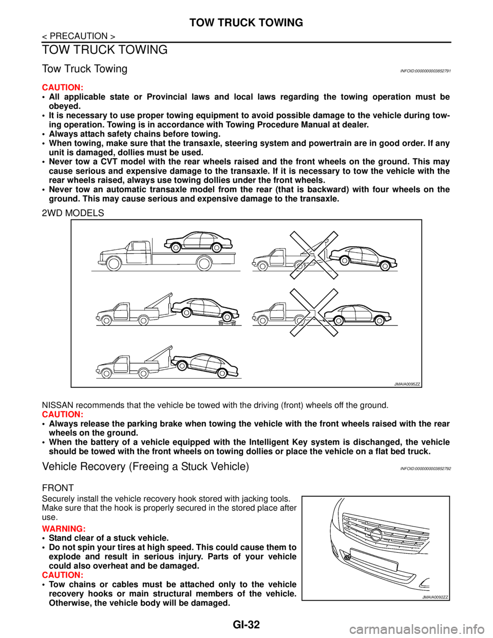
CAUTION:
All applicable state or Provincial laws and local laws regarding the towing operation must be
obeyed.
It is necessary to use proper towing equipment to avoid possible damage to the vehicle during tow-
ing operation. Towing is in accordance with Towing Procedure Manual at dealer.
Always attach safety chains before towing.
When towing, make sure that the transaxle, steering system and powertrain are in good order. If any
unit is damaged, dollies must be used.
Never tow a CVT model with the rear wheels raised and the front wheels on the ground. This may
cause serious and expensive damage to the transaxle. If it is necessary to tow the vehicle with the
rear wheels raised, always use towing dollies under the front wheels.
Never tow an automatic transaxle model from the rear (that is backward) with four wheels on the
ground. This may cause serious and expensive damage to the transaxle.
2WD MODELS
NISSAN recommends that the vehicle be towed with the driving (front) wheels off the ground.
CAUTION:
Always release the parking brake when towing the vehicle with the front wheels raised with the rear
wheels on the ground.
When the battery of a vehicle equipped with the Intelligent Key system is dischanged, the vehicle
should be towed with the front wheels on towing dollies or place the vehicle on a flat bed truck.
Vehicle Recovery (Freeing a Stuck Vehicle)INFOID:0000000003852792
FRONT
Securely install the vehicle recovery hook stored with jacking tools.
Make sure that the hook is properly secured in the stored place after
use.
WARNING:
Stand clear of a stuck vehicle.
Do not spin your tires at high speed. This could cause them to
explode and result in serious injury. Parts of your vehicle
could also overheat and be damaged.
CAUTION:
Tow chains or cables must be attached only to the vehicle
recovery hooks or main structural members of the vehicle.
Otherwise, the vehicle body will be damaged.
JMAIA0095ZZ
JMAIA0092ZZ