Page 2526 of 5121
TOW TRUCK TOWING
GI-33
< PRECAUTION >
C
D
E
F
G
H
I
J
K
L
MB
GI
N
O
P
Do not use the vehicle tie downs to free a vehicle stuck in sand, snow, mud, etc. Never tow the vehi-
cle using the vehicle tie downs or recovery hooks.
Always pull the cable straight out from the front of the vehicle. Never pull on the hook at an angle.
Pulling devices should be routed so they do not touch any part of the suspension, steering, brake or
cooling systems.
Pulling devices such as ropes or canvas straps are not recommended for use in vehicle towing or
recovery.
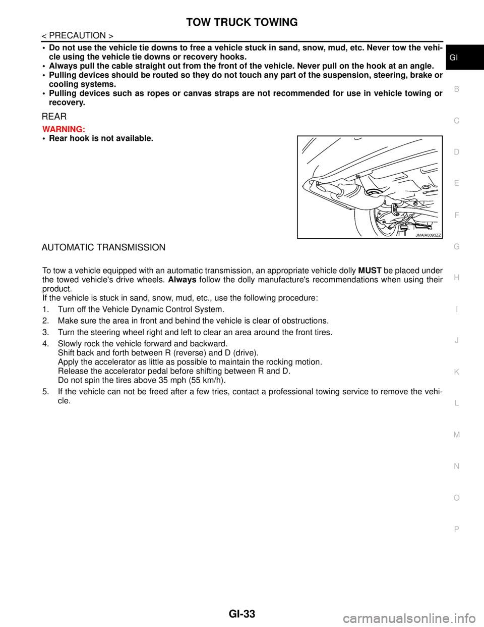
REAR
WARNING:
Rear hook is not available.
AUTOMATIC TRANSMISSION
To tow a vehicle equipped with an automatic transmission, an appropriate vehicle dolly MUST be placed under
the towed vehicle's drive wheels. Always follow the dolly manufacture's recommendations when using their
product.
If the vehicle is stuck in sand, snow, mud, etc., use the following procedure:
1. Turn off the Vehicle Dynamic Control System.
2. Make sure the area in front and behind the vehicle is clear of obstructions.
3. Turn the steering wheel right and left to clear an area around the front tires.
4. Slowly rock the vehicle forward and backward.
Shift back and forth between R (reverse) and D (drive).
Apply the accelerator as little as possible to maintain the rocking motion.
Release the accelerator pedal before shifting between R and D.
Do not spin the tires above 35 mph (55 km/h).
5. If the vehicle can not be freed after a few tries, contact a professional towing service to remove the vehi-
cle.
JMAIA0093ZZ
Page 2622 of 5121
EVAPORATOR
HA-53
< ON-VEHICLE REPAIR >
C
D
E
F
G
H
J
K
L
MA
B
HA
N
O
P
Removal and InstallationINFOID:0000000003795855
REMOVAL
1. Remove evaporator pipe assembly. Refer to HA-54, "Exploded View".
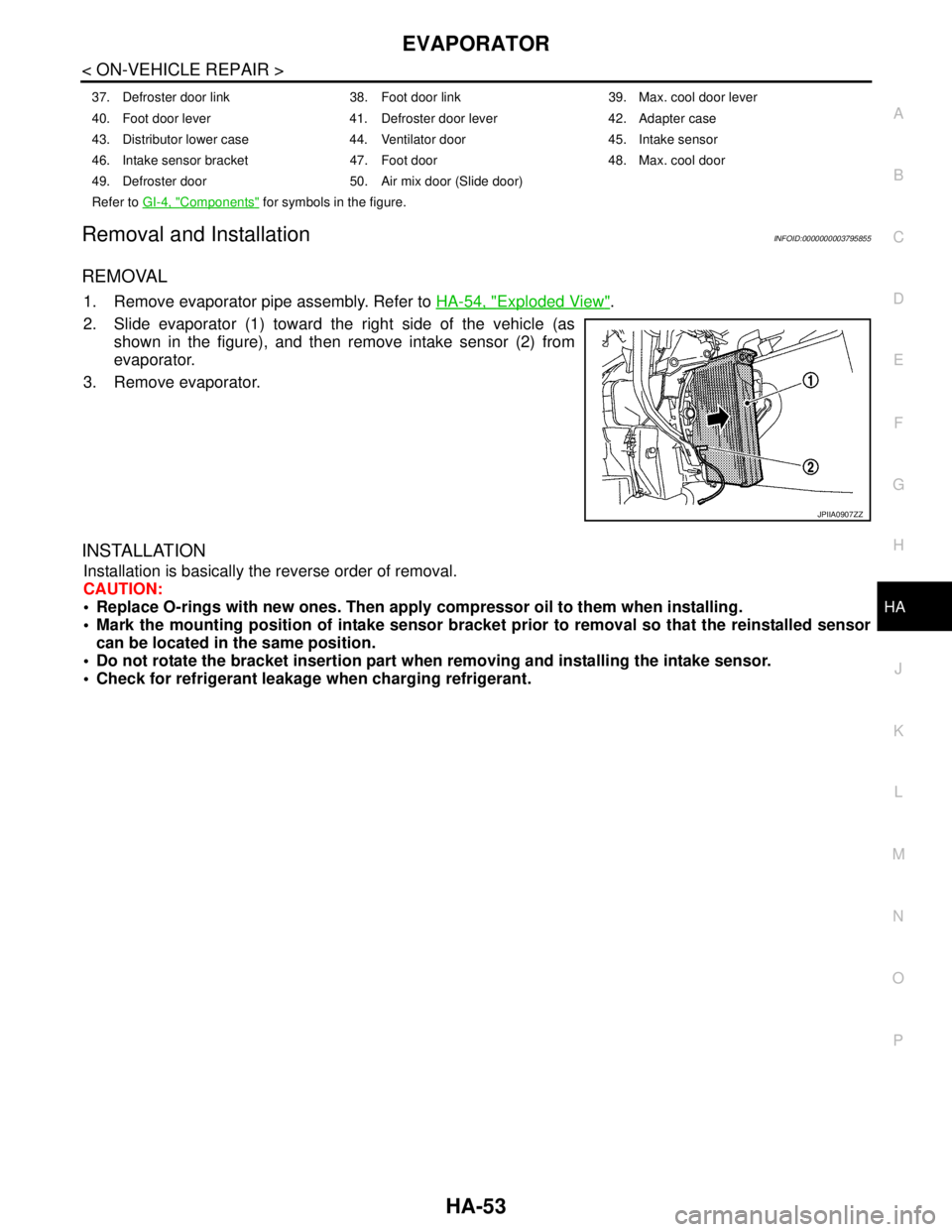
2. Slide evaporator (1) toward the right side of the vehicle (as
shown in the figure), and then remove intake sensor (2) from
evaporator.
3. Remove evaporator.
INSTALLATION
Installation is basically the reverse order of removal.
CAUTION:
Replace O-rings with new ones. Then apply compressor oil to them when installing.
Mark the mounting position of intake sensor bracket prior to removal so that the reinstalled sensor
can be located in the same position.
Do not rotate the bracket insertion part when removing and installing the intake sensor.
Check for refrigerant leakage when charging refrigerant.
37. Defroster door link 38. Foot door link 39. Max. cool door lever
40. Foot door lever 41. Defroster door lever 42. Adapter case
43. Distributor lower case 44. Ventilator door 45. Intake sensor
46. Intake sensor bracket 47. Foot door 48. Max. cool door
49. Defroster door 50. Air mix door (Slide door)
Refer to GI-4, "
Components" for symbols in the figure.
JPIIA0907ZZ
Page 3009 of 5121
INT-32
< ON-VEHICLE REPAIR >
FRONT DOOR FINISHER
7. Disconnect lock knob cable (1), inside handle cable (2), power
window switch finisher harness connectors (B) and seat memory
switch harness connector (A).
8. Remove front door finisher.
9. Remove the following parts after removing front door finisher.
Front door inside handle. Refer to DLK-223, "
INSIDE HANDLE : Removal and Installation".
Seat memory switch. Refer to ADP-137, "
Removal and Installation".
Disengage power window switch finisher (1) pawls as shown by the figure by pressing them toward the
arrow, then remove the power window switch finisher (1) from the door finisher (2).
INSTALLATION
Install in the reverse order of removal.
CAUTION:
When installing door finisher, check that clips are securely fitted in panel holes on body, and then
press them in.
PASSENGER SIDE
JMJIA1761ZZ
JMJIA1954ZZ
Page 3028 of 5121
HEADLINING
INT-51
< ON-VEHICLE REPAIR >
C
D
E
F
G
H
I
K
L
MA
B
INT
N
O
P
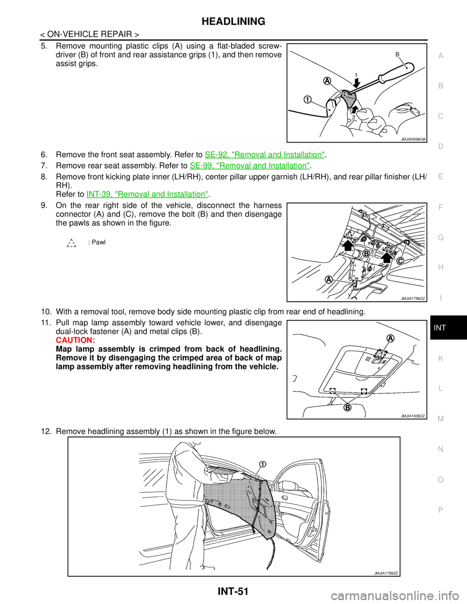
5. Remove mounting plastic clips (A) using a flat-bladed screw-
driver (B) of front and rear assistance grips (1), and then remove
assist grips.
6. Remove the front seat assembly. Refer to SE-92, "
Removal and Installation".
7. Remove rear seat assembly. Refer to SE-99, "
Removal and Installation".
8. Remove front kicking plate inner (LH/RH), center pillar upper garnish (LH/RH), and rear pillar finisher (LH/
RH).
Refer to INT-39, "
Removal and Installation".
9. On the rear right side of the vehicle, disconnect the harness
connector (A) and (C), remove the bolt (B) and then disengage
the pawls as shown in the figure.
10. With a removal tool, remove body side mounting plastic clip from rear end of headlining.
11. Pull map lamp assembly toward vehicle lower, and disengage
dual-lock fastener (A) and metal clips (B).
CAUTION:
Map lamp assembly is crimped from back of headlining.
Remove it by disengaging the crimped area of back of map
lamp assembly after removing headlining from the vehicle.
12. Remove headlining assembly (1) as shown in the figure below.
JMJIA0096GB
: Pawl
JMJIA1788ZZ
JMJIA1008ZZ
JMJIA1789ZZ
Page 3032 of 5121
HEADLINING
INT-55
< ON-VEHICLE REPAIR >
C
D
E
F
G
H
I
K
L
MA
B
INT
N
O
P
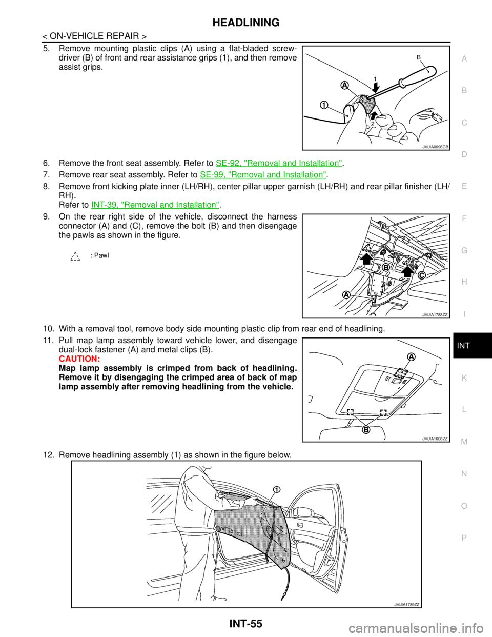
5. Remove mounting plastic clips (A) using a flat-bladed screw-
driver (B) of front and rear assistance grips (1), and then remove
assist grips.
6. Remove the front seat assembly. Refer to SE-92, "
Removal and Installation".
7. Remove rear seat assembly. Refer to SE-99, "
Removal and Installation".
8. Remove front kicking plate inner (LH/RH), center pillar upper garnish (LH/RH) and rear pillar finisher (LH/
RH).
Refer to INT-39, "
Removal and Installation".
9. On the rear right side of the vehicle, disconnect the harness
connector (A) and (C), remove the bolt (B) and then disengage
the pawls as shown in the figure.
10. With a removal tool, remove body side mounting plastic clip from rear end of headlining.
11. Pull map lamp assembly toward vehicle lower, and disengage
dual-lock fastener (A) and metal clips (B).
CAUTION:
Map lamp assembly is crimped from back of headlining.
Remove it by disengaging the crimped area of back of map
lamp assembly after removing headlining from the vehicle.
12. Remove headlining assembly (1) as shown in the figure below.
JMJIA0096GB
: Pawl
JMJIA1788ZZ
JMJIA1008ZZ
JMJIA1789ZZ
Page 3038 of 5121
REAR SUNSHADE CONTROL UNIT
INT-61
< ON-VEHICLE REPAIR >
C
D
E
F
G
H
I
K
L
MA
B
INT
N
O
P
REAR SUNSHADE CONTROL UNIT
Exploded ViewINFOID:0000000003840071
Removal and InstallationINFOID:0000000003840072
REMOVAL
1. Remove the rear parcel shelf finisher.
Refer to INT-43, "
Removal and Installation".
2. Remove the rear sunshade control unit bracket bolt (A).
3. Remove the rear sunshade control unit. (1) Pull toward the
direction of the arrow.
INSTALLATION
Install in the reverse order of removal.
1. Rear sunshade control unit
JMJIA1949ZZ
JMJIA1950ZZ
JMJIA1951ZZ
Page 3056 of 5121
IP-16
< ON-VEHICLE REPAIR >
INSTRUMENT PANEL ASSEMBLY
19. Remove glove box assembly.
Remove glove box assembly (1) fixing screws (A).
Open the glove box lid.
Remove glove box assembly fixing screws (B).
Pull back glove box assembly.
Disconnect harness connector.
20. Remove DVD player. Refer to AV-650, "
Removal and Installation".
21. Remove instrument side panel RH.
Remove instrument side panel RH (1) fixing screw (A).
Pull toward the direction the arrow is pointing.
22. Remove instrument lower cover RH.
Disengage instrument lower cover RH (1) fixing clip, pawl and
metal clips.
Pull the instrument lower cover RH crosswise.
23. Remove selector lever knob. Refer to TM-155, "
Removal and Installation".
: Pawl
JMJIA1901ZZ
: Clip
: Pawl
JMJIA1902ZZ
: Clip
: Pawl
: Metal clip
JMJIA1903ZZ
Page 3060 of 5121
IP-20
< ON-VEHICLE REPAIR >
INSTRUMENT PANEL ASSEMBLY
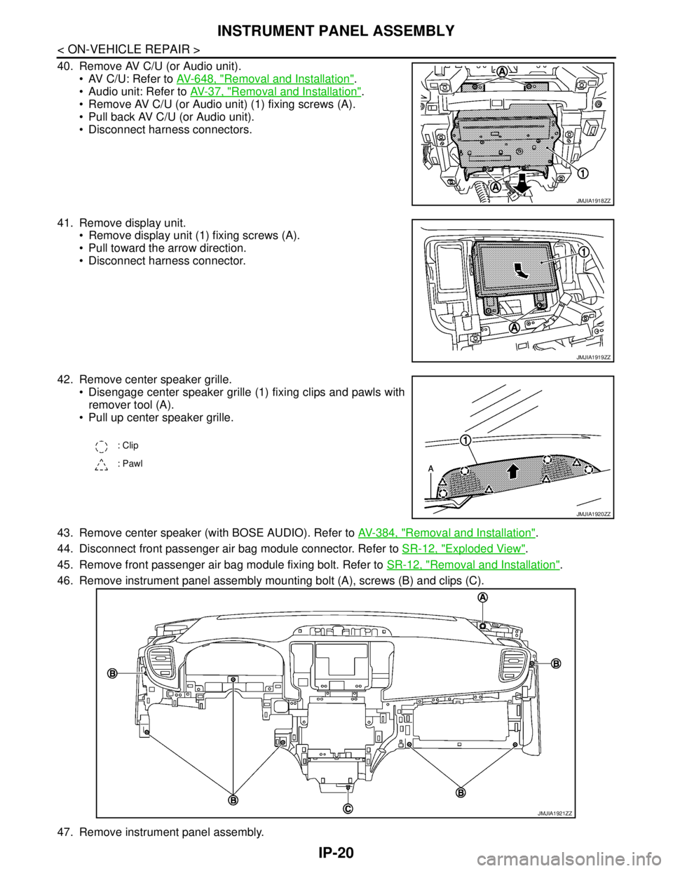
40. Remove AV C/U (or Audio unit).
AV C/U: Refer to AV-648, "
Removal and Installation".
Audio unit: Refer to AV-37, "
Removal and Installation".
Remove AV C/U (or Audio unit) (1) fixing screws (A).
Pull back AV C/U (or Audio unit).
Disconnect harness connectors.
41. Remove display unit.
Remove display unit (1) fixing screws (A).
Pull toward the arrow direction.
Disconnect harness connector.
42. Remove center speaker grille.
Disengage center speaker grille (1) fixing clips and pawls with
remover tool (A).
Pull up center speaker grille.
43. Remove center speaker (with BOSE AUDIO). Refer to AV-384, "
Removal and Installation".
44. Disconnect front passenger air bag module connector. Refer to SR-12, "
Exploded View".
45. Remove front passenger air bag module fixing bolt. Refer to SR-12, "
Removal and Installation".
46. Remove instrument panel assembly mounting bolt (A), screws (B) and clips (C).
47. Remove instrument panel assembly.
JMJIA1918ZZ
JMJIA1919ZZ
: Clip
: Pawl
JMJIA1920ZZ
JMJIA1921ZZ