2008 NISSAN TEANA relay
[x] Cancel search: relayPage 5044 of 5121
WW-32
< COMPONENT DIAGNOSIS >
HEADLAMP WASHER CIRCUIT
HEADLAMP WASHER CIRCUIT
Component Function CheckINFOID:0000000003761599
1.CHECK HEADLAMP WASHER OPERATION
CONSULT-III ACTIVE TEST
1. Select “HEAD LAMP WASHER” of IPDM E/R active test item.
2. With operating the test item, check headlamp operation.
Is headlamp washer operation normally?
YES >> Headlamp washer circuit is normal.
NO >> Refer to WW-32, "
Diagnosis Procedure".
Diagnosis ProcedureINFOID:0000000003761600
1.CHECK HEADLAMP WASHER FUSIBLE LINK
1. Turn the ignition switch OFF.
2. Check that the headlamp washer 40A fusible link (#J) is not fusing.
Is the fusible link fusing?
YES >> Replace the fusible link after repairing the applicable circuit.
NO >> GO TO 2.
2.CHECK HEADLAMP WASHER RELAY POWER SUPPLY
1. Remove headlamp washer relay.
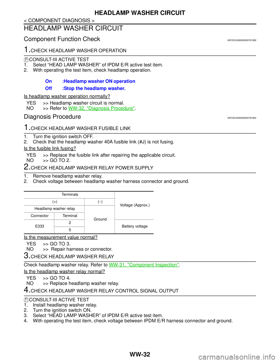
2. Check voltage between headlamp washer harness connector and ground.
Is the measurement value normal?
YES >> GO TO 3.
NO >> Repair harness or connector.
3.CHECK HEADLAMP WASHER RELAY
Check headlamp washer relay. Refer to WW-31, "
Component Inspection".
Is the headlamp washer relay normal?
YES >> GO TO 4.
NO >> Replace headlamp washer relay.
4.CHECK HEADLAMP WASHER RELAY CONTROL SIGNAL OUTPUT
CONSULT-III ACTIVE TEST
1. Install headlamp washer relay.
2. Turn the ignition switch ON.
3. Select “HEAD LAMP WASHER” of IPDM E/R active test item.
4. With operating the test item, check voltage between IPDM E/R harness connector and ground.On :Headlamp washer ON operation
Off :Stop the headlamp washer.
Te r m i n a l s
Voltage (Approx.) (+) (−)
Headlamp washer relay
Ground Connector Terminal
E3332
Battery voltage
5
Page 5045 of 5121

HEADLAMP WASHER CIRCUIT
WW-33
< COMPONENT DIAGNOSIS >
C
D
E
F
G
H
I
J
K
MA
B
WW
N
O
P
Is the measurement value normal?
YES >> GO TO 7.
Fixed at 0 V >> GO TO 5.
Fixed at battery voltage >>Replace IPDM E/R.
5.CHECK HEADLAMP WASHER RELAY CONTROL SIGNAL OPEN CIRCUIT
1. Remove headlamp washer relay.
2. Disconnect IPDM E/R harness connector.
3. Check continuity between IPDM E/R harness connector and headlamp washer relay harness connector.
Does continuity exist?
YES >> GO TO 6.
NO >> Repair the harness or connector.
6.CHECK HEADLAMP WASHER RELAY CONTROL SIGNAL SHORT CIRCUIT
Check continuity between IPDM E/R harness connector and ground.
Does continuity exist?
YES >> Repair the harness or connector.
NO >> Replace IPDM E/R.
7.CHECK HEADLAMP WASHER PUMP OPEN CIRCUIT
1. Remove headlamp washer relay.
2. Disconnect headlamp washer pump connector.
3. Check continuity between headlamp washer relay harness connector and headlamp washer pump har-
ness connector.
Does continuity exist?
YES >> GO TO 8.
NO >> Repair the harness or connector.
8.CHECK HEADLAMP WASHER PUMP (GND) OPEN CIRCUIT
Check continuity headlamp washer pump harness connector and ground.
Te r m i n a l s
Te s t i t e m
Voltage (Approx.) (+) (−)
IPDM E/R
GroundHEAD LAMP
WASHER
Connector Terminal
E10 17On 0 V
Off Battery voltage
IPDM E/R Headlamp washer relay
Continuity
Connector Terminal Connector Terminal
E10 17 E333 1 Existed
IPDM E/R
GroundContinuity
Connector Terminal
E10 17 Not existed
Headlamp washer relay Headlamp washer pump
Continuity
Connector Terminal Connector Terminal
E333 3 E334 1 Existed
Page 5056 of 5121

WW-44
< ECU DIAGNOSIS >
BCM (BODY CONTROL MODULE)
REQ SW -RRNOTE:
The item is indicated, but not monitored. Off
REQ SW -RRNOTE:
The item is indicated, but not monitored. Off
REQ SW -BD/TRTrunk lid opener request switch is not pressed Off
Trunk lid opener request switch is pressed On
PUSH SWPush-button ignition switch (push switch) is not pressed Off
Push-button ignition switch (push switch) is pressed On
IGN RLY2 -F/BIgnition switch in OFF or ACC position Off
Ignition switch in ON position On
CLUCH SWNOTE:
The item is indicated, but not monitored. Off
BRAKE SW 1The brake pedal is not depressed On
The brake pedal is depressed Off
DETE/CANCL SWSelector lever in P position Off
Selector lever in any position other than P On
SFT PN/N SWSelector lever in any position other than P and N Off
Selector lever in P or N position On
S/L -LOCKSteering is locked Off
Steering is unlocked On
S/L -UNLOCKSteering is unlocked Off
Steering is locked On
S/L RELAY-F/BIgnition switch in OFF or ACC position Off
Ignition switch in ON position On
UNLK SEN -DRDriver door is unlocked Off
Driver door is locked On
PUSH SW -IPDMPush-button ignition switch (push-switch) is not pressed Off
Push-button ignition switch (push-switch) is pressed On
IGN RLY1 -F/BIgnition switch in OFF or ACC position Off
Ignition switch in ON position On
DETE SW -IPDMSelector lever in P position Off
Selector lever in any position other than P On
SFT PN -IPDMSelector lever in any position other than P and N Off
Selector lever in P or N position On
SFT P -METSelector lever in any position other than P Off
Selector lever in P position On
SFT N -METSelector lever in any position other than N Off
Selector lever in N position On
ENGINE STATEEngine stopped Stop
While the engine stalls Stall
At engine cranking Crank
Engine running Run
S/L LOCK-IPDMSteering is locked Off
Steering is unlocked On Monitor Item Condition Value/Status
Page 5057 of 5121

BCM (BODY CONTROL MODULE)
WW-45
< ECU DIAGNOSIS >
C
D
E
F
G
H
I
J
K
MA
B
WW
N
O
P
S/L UNLK-IPDMSteering is unlocked Off
Steering is locked On
S/L RELAY-REQIgnition switch in OFF or ACC position Off
Ignition switch in ON position On
VEH SPEED 1 While driving Equivalent to speedometer reading
VEH SPEED 2 While driving Equivalent to speedometer reading
DOOR STAT-DRDriver door is locked LOCK
Wait with selective UNLOCK operation (5 seconds) READY
Driver door is unlocked UNLOCK
DOOR STAT-ASPassenger door is locked LOCK
Wait with selective UNLOCK operation (5 seconds) READY
Passenger door is unlocked UNLOCK
ID OK FLAGIgnition switch in ACC or ON position Reset
Ignition switch in OFF position Set
PRMT ENG STRTThe engine start is prohibited Reset
The engine start is permitted Set
PRMT RKE STRTNOTE:
The item is indicated, but not monitored. Reset
KEY SW -SLOTThe key is not inserted into key slot Off
The key is inserted into key slot On
RKE OPE COUN1 During the operation of the key Operation frequency of the key
RKE OPE COUN2NOTE:
The item is indicated, but not monitored. —
CONFRM ID ALLThe key ID that the key slot receives does not accord with any key
ID registered to BCM.Ye t
The key ID that the key slot receives accords with any key ID regis-
tered to BCM.Done
CONFIRM ID4The key ID that the key slot receives does not accord with the fourth
key ID registered to BCM.Ye t
The key ID that the key slot receives accords with the fourth key ID
registered to BCM.Done
CONFIRM ID3The key ID that the key slot receives does not accord with the third
key ID registered to BCM.Ye t
The key ID that the key slot receives accords with the third key ID
registered to BCM.Done
CONFIRM ID2The key ID that the key slot receives does not accord with the sec-
ond key ID registered to BCM.Ye t
The key ID that the key slot receives accords with the second key
ID registered to BCM.Done
CONFIRM ID1The key ID that the key slot receives does not accord with the first
key ID registered to BCM.Ye t
The key ID that the key slot receives accords with the first key ID
registered to BCM.Done
TP 4The ID of fourth key is not registered to BCM Yet
The ID of fourth key is registered to BCM Done
TP 3The ID of third key is not registered to BCM Yet
The ID of third key is registered to BCM Done Monitor Item Condition Value/Status
Page 5062 of 5121
WW-50
< ECU DIAGNOSIS >
BCM (BODY CONTROL MODULE)
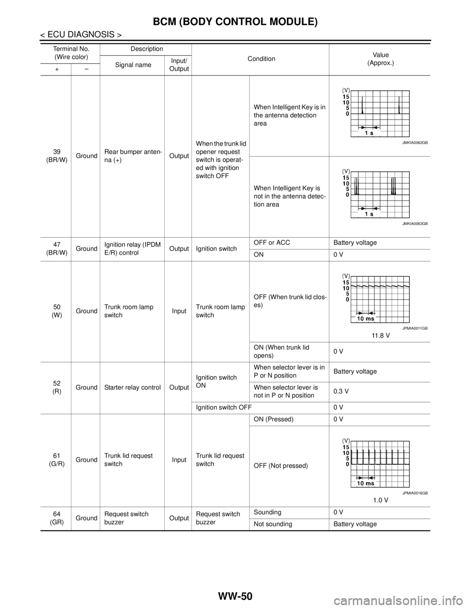
39
(BR/W)GroundRear bumper anten-
na (+)OutputWhen the trunk lid
opener request
switch is operat-
ed with ignition
switch OFFWhen Intelligent Key is in
the antenna detection
area
When Intelligent Key is
not in the antenna detec-
tion area
47
(BR/W)GroundIgnition relay (IPDM
E/R) controlOutput Ignition switchOFF or ACC Battery voltage
ON 0 V
50
(W)GroundTrunk room lamp
switchInputTrunk room lamp
switchOFF (When trunk lid clos-
es)
11 . 8 V
ON (When trunk lid
opens)0 V
52
(R)Ground Starter relay control OutputIgnition switch
ONWhen selector lever is in
P or N positionBattery voltage
When selector lever is
not in P or N position0.3 V
Ignition switch OFF 0 V
61
(G/R)GroundTrunk lid request
switchInputTrunk lid request
switchON (Pressed) 0 V
OFF (Not pressed)
1.0 V
64
(GR)GroundRequest switch
buzzerOutputRequest switch
buzzerSounding 0 V
Not sounding Battery voltage Te r m i n a l N o .
(Wire color)Description
ConditionVa l u e
(Approx.)
Signal nameInput/
Output +–
JMKIA0062GB
JMKIA0063GB
JPMIA0011GB
JPMIA0016GB
Page 5066 of 5121
WW-54
< ECU DIAGNOSIS >
BCM (BODY CONTROL MODULE)
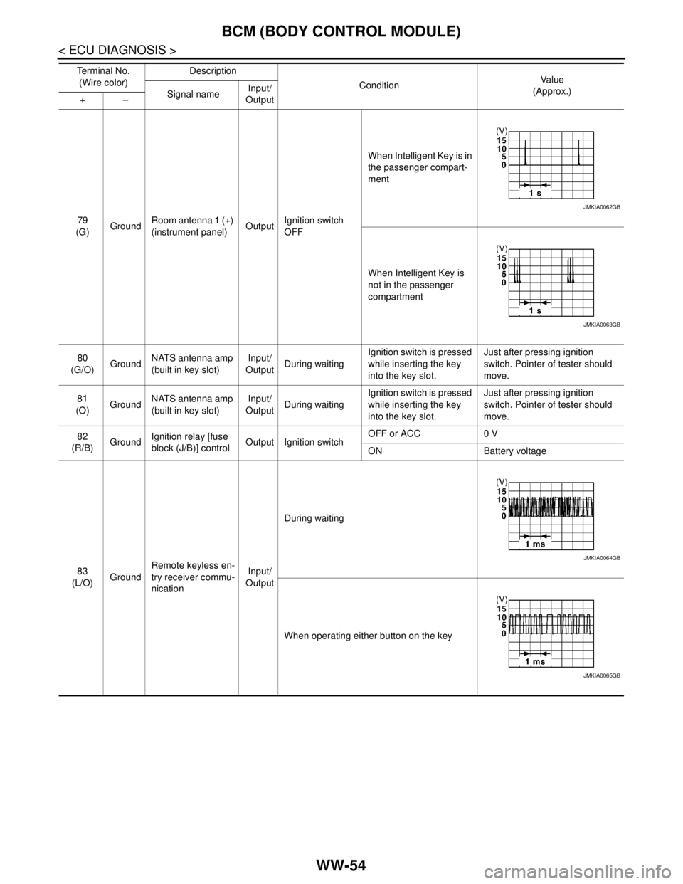
79
(G)GroundRoom antenna 1 (+)
(instrument panel)OutputIgnition switch
OFFWhen Intelligent Key is in
the passenger compart-
ment
When Intelligent Key is
not in the passenger
compartment
80
(G/O)GroundNATS antenna amp
(built in key slot)Input/
OutputDuring waitingIgnition switch is pressed
while inserting the key
into the key slot.Just after pressing ignition
switch. Pointer of tester should
move.
81
(O)GroundNATS antenna amp
(built in key slot)Input/
OutputDuring waitingIgnition switch is pressed
while inserting the key
into the key slot.Just after pressing ignition
switch. Pointer of tester should
move.
82
(R/B)GroundIgnition relay [fuse
block (J/B)] controlOutput Ignition switchOFF or ACC 0 V
ON Battery voltage
83
(L/O)GroundRemote keyless en-
try receiver commu-
nicationInput/
OutputDuring waiting
When operating either button on the key Te r m i n a l N o .
(Wire color)Description
ConditionVa l u e
(Approx.)
Signal nameInput/
Output +–
JMKIA0062GB
JMKIA0063GB
JMKIA0064GB
JMKIA0065GB
Page 5069 of 5121
BCM (BODY CONTROL MODULE)
WW-57
< ECU DIAGNOSIS >
C
D
E
F
G
H
I
J
K
MA
B
WW
N
O
P
93
(Y)Ground ON indicator lamp Output Ignition switchOFF (LOCK indicator is
not illuminated)Battery voltage
ON or ACC 0 V
95
(L)Ground ACC relay control Output Ignition switchOFF 0 V
ACC or ON Battery voltage
96
(Y/R)GroundControl device (de-
tention switch) pow-
er supplyOutput — Battery voltage
97
(L/O)GroundSteering lock condi-
tion No. 1Input Steering lockLOCK status 0 V
UNLOCK status Battery voltage
98
(G/R)GroundSteering lock condi-
tion No. 2Input Steering lockLOCK status Battery voltage
UNLOCK status 0 V
99
(G/B)GroundSelector lever P po-
sition switchInput Selector leverP position 0 V
Any position other than P Battery voltage
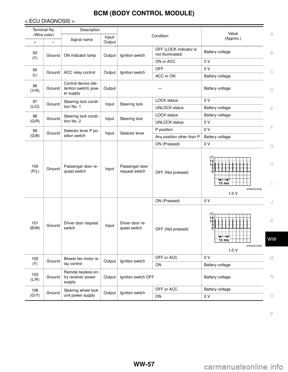
100
(P/L)GroundPassenger door re-
quest switchInputPassenger door
request switchON (Pressed) 0 V
OFF (Not pressed)
1.0 V
101
(B/W)GroundDriver door request
switchInputDriver door re-
quest switchON (Pressed) 0 V
OFF (Not pressed)
1.0 V
102
(Y)GroundBlower fan motor re-
lay controlOutput Ignition switchOFF or ACC 0 V
ON Battery voltage
103
(L/R)GroundRemote keyless en-
try receiver power
supplyOutput Ignition switch OFF Battery voltage
106
(G/Y)GroundSteering wheel lock
unit power supplyOutput Ignition switchOFF or ACC Battery voltage
ON 0 V Te r m i n a l N o .
(Wire color)Description
ConditionVa l u e
(Approx.)
Signal nameInput/
Output +–
JPMIA0016GB
JPMIA0016GB
Page 5076 of 5121
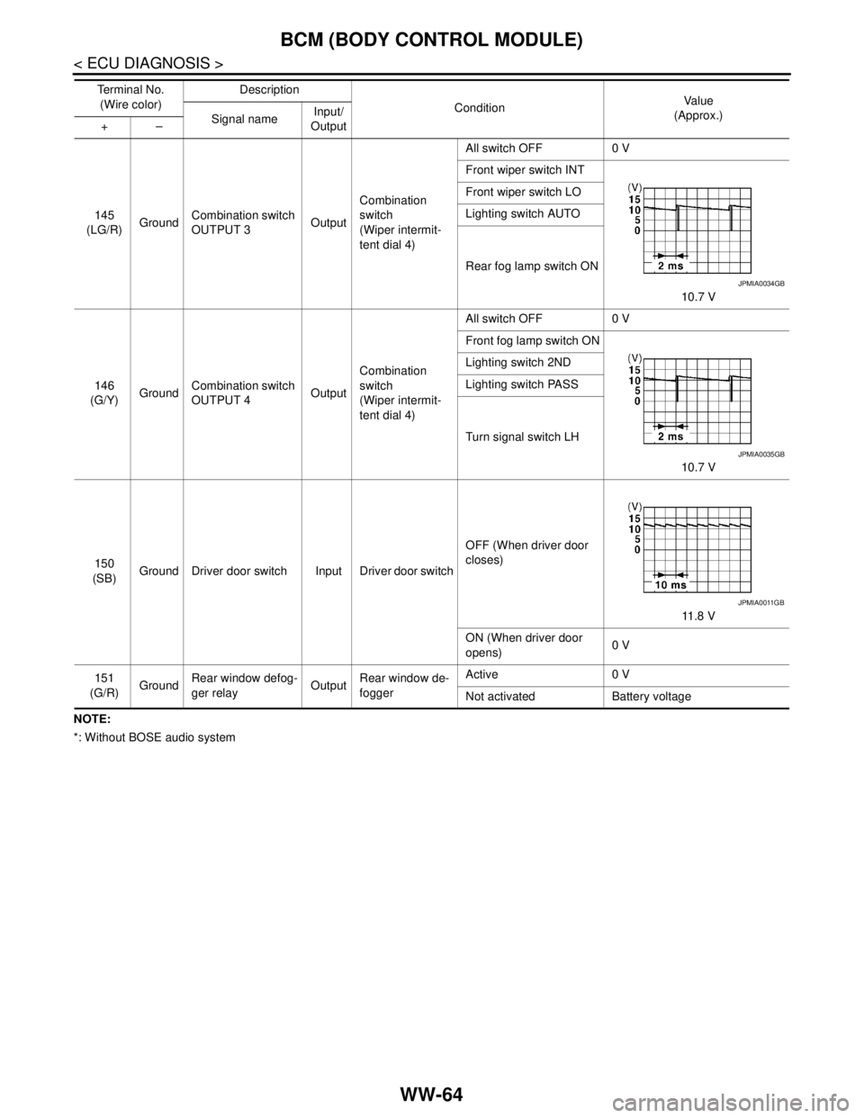
WW-64
< ECU DIAGNOSIS >
BCM (BODY CONTROL MODULE)
NOTE:
*: Without BOSE audio system145
(LG/R)GroundCombination switch
OUTPUT 3OutputCombination
switch
(Wiper intermit-
tent dial 4)All switch OFF 0 V
Front wiper switch INT
10.7 V Front wiper switch LO
Lighting switch AUTO
Rear fog lamp switch ON
146
(G/Y)GroundCombination switch
OUTPUT 4OutputCombination
switch
(Wiper intermit-
tent dial 4)All switch OFF 0 V
Front fog lamp switch ON
10.7 V Lighting switch 2ND
Lighting switch PASS
Turn signal switch LH
150
(SB)Ground Driver door switch Input Driver door switchOFF (When driver door
closes)
11 . 8 V
ON (When driver door
opens)0 V
151
(G/R)GroundRear window defog-
ger relayOutputRear window de-
foggerActive 0 V
Not activated Battery voltage Te r m i n a l N o .
(Wire color)Description
ConditionVa l u e
(Approx.)
Signal nameInput/
Output +–
JPMIA0034GB
JPMIA0035GB
JPMIA0011GB