2008 NISSAN TEANA relay
[x] Cancel search: relayPage 4515 of 5121
![NISSAN TEANA 2008 Service Manual TM-42
< COMPONENT DIAGNOSIS >[CVT: RE0F09B]
P0615 START SIGNAL
P0615 START SIGNAL
DescriptionINFOID:0000000003848949
TCM controls starter relay in IPDM E/R.
TCM switches starter relay ON at “P� NISSAN TEANA 2008 Service Manual TM-42
< COMPONENT DIAGNOSIS >[CVT: RE0F09B]
P0615 START SIGNAL
P0615 START SIGNAL
DescriptionINFOID:0000000003848949
TCM controls starter relay in IPDM E/R.
TCM switches starter relay ON at “P�](/manual-img/5/57391/w960_57391-4514.png)
TM-42
< COMPONENT DIAGNOSIS >[CVT: RE0F09B]
P0615 START SIGNAL
P0615 START SIGNAL
DescriptionINFOID:0000000003848949
TCM controls starter relay in IPDM E/R.
TCM switches starter relay ON at “P” or “N” position and allows to crank engine.
Then it prohibits cranking other than at “P” or “N” position.
DTC LogicINFOID:0000000003848950
DTC DETECTION LOGIC
DTC CONFIRMATION PROCEDURE
CAUTION:
Always drive vehicle at a safe speed.
NOTE:
Immediately after performing any “DTC CONFIRMATION PROCEDURE”, always turn ignition switch OFF.
Then wait at least 10 seconds before performing the next test.
1.CHECK DTC DETECTION
With CONSULT-III
1. Turn ignition switch ON.
2. Perform “Self-Diagnostic Results” mode for “TRANSMISSION”.
Is
“P0615 STARTER RELAY/CIRC” detected?
YES >> Go to TM-42, "Diagnosis Procedure".
NO >> Check intermittent incident. Refer to GI-35, "
Intermittent Incident".
Diagnosis ProcedureINFOID:0000000003848951
1.CHECK STARTER RELAY SIGNAL
1. Turn ignition switch ON.
2. Disconnect IPDM E/R harness connector.
3. Check voltage between IPDM E/R vehicle side harness connector terminal and ground.
Is the inspection result normal?
YES >> Check starter relay and starter control relay. Refer to STR-10, "Wiring Diagram - STARTING SYS-
TEM -".
NO >> GO TO 2.
2.CHECK HARNESS BETWEEN TCM AND IPDM E/R (PART 1)
1. Turn ignition switch OFF.
2. Disconnect TCM connector.
3. Check continuity between TCM vehicle side harness connector terminal and IPDM E/R vehicle side har-
ness connector terminal.
DTCItem
(CONSULT-III screen term)Malfunction is detected when... Possible cause
P0615 STARTER RELAY/CIRCIf this signal is ON other than in “P” or “N” po-
sition, this is judged to be a malfunction.
(And if it is OFF in “P” or “N” position, this too
is judged to be a malfunction.) Harness or connectors
(Starter relay and TCM circuit is open or
shorted.)
Starter relay circuit
IPDM E/R vehicle side harness connector
GroundCondition Voltage (Approx.)
Connector Terminal
F12 72Selector lever in “P” and “N” positions Battery voltage
Selector lever in other positions 0 V
Page 4587 of 5121
![NISSAN TEANA 2008 Service Manual TM-114
< ECU DIAGNOSIS >[CVT: RE0F09B]
TCM
9
(L/R)— CHIP SELECT (SEL1) — — —
10
(BR/R)— DATA I/O (SEL3) — — —
11
(BR/W)Ground PNP switch 1 Input Ignition switch ONSelector lever in “ NISSAN TEANA 2008 Service Manual TM-114
< ECU DIAGNOSIS >[CVT: RE0F09B]
TCM
9
(L/R)— CHIP SELECT (SEL1) — — —
10
(BR/R)— DATA I/O (SEL3) — — —
11
(BR/W)Ground PNP switch 1 Input Ignition switch ONSelector lever in “](/manual-img/5/57391/w960_57391-4586.png)
TM-114
< ECU DIAGNOSIS >[CVT: RE0F09B]
TCM
9
(L/R)— CHIP SELECT (SEL1) — — —
10
(BR/R)— DATA I/O (SEL3) — — —
11
(BR/W)Ground PNP switch 1 Input Ignition switch ONSelector lever in “R”, “N” and “D”
positions0 V
Selector lever in other positionsBattery
voltage
13
(V)GroundCVT fluid temperature sen-
sor Input Ignition switch ONWhen CVT fluid temperature is
20°C (68°F)1.9 – 2.2
V
When CVT fluid temperature is
80°C (176°F)0.8 – 1.1
V
14
(R/W)GroundTransmission fluid pres-
sure sensor B (Primary
pressure sensor)Input
“N” position idle0.5 – 0.8
V
15
(V/W)GroundTransmission fluid pres-
sure sensor A (Secondary
pressure sensor)Input1.0 – 1.5
V
19
(G/B)Ground Reverse lamp relay Output Ignition switch ONSelector lever in “R” position 0 V
Selector lever in other positionsBattery
voltage
20
(R/B)Ground Starter relay Output Ignition switch ONSelector lever in “N”, “P” posi-
tionsBattery
voltage
Selector lever in other positions 0 V
25
(W/R)Ground Sensor ground Output Always 0 V
26
(L/O)Ground Sensor power OutputIgnition switch ON —4.75 –
5.25 V
Ignition switch OFF — 0 V
27
(R/G)Ground Step motor D Output
Within 2 seconds after ignition switch ON, measure the
time using the pulse width measurement function (Hi
level) of CONSULT-III.*
CAUTION:
Connect the diagnosis data link cable to the vehicle
diagnosis connector.10.0
msec
28
(R)Ground Step motor C Output30.0
msec
29
(O/B)Ground Step motor B Output10.0
msec
30
(G/R)Ground Step motor A Output30.0
msec
31
(P)— CAN-L Input/Output — —
32
(L)— CAN-H Input/Output — —
33
(LG)GroundInput speed sensor (Prima-
ry speed sensor)InputWhen driving at 20 km/h (12 MPH) in “L” position, use
the CONSULT-III pulse frequency measuring function.680 Hz
34
(LG/R)GroundOutput speed sensor (Sec-
ondary speed sensor)InputWhen driving at 20 km/h (12 MPH) in “D” position, use
the CONSULT-III pulse frequency measuring function.400 Hz
37
(V/R)GroundLock-up select solenoid
valveOutput Ignition switch ONSelector lever in “P”, “N” posi-
tions Battery
voltage
Wait at least for 5 seconds with
the selector lever in “R”, “D” and
“L” positions.0 V Te r m i n a l N o .
(Wire color)Description
ConditionVa l u e
(Approx.)
+ - Signal name Input/Output
Page 4595 of 5121
![NISSAN TEANA 2008 Service Manual TM-122
< ECU DIAGNOSIS >[CVT: RE0F09B]
TCM
If DTC “U1000 CAN COMM CIRCUIT” is indicated with other DTCs, start from a diagnosis for “DTC
U1000 CAN COMMUNICATION LINE”. Refer to TM-41
.
*1: T NISSAN TEANA 2008 Service Manual TM-122
< ECU DIAGNOSIS >[CVT: RE0F09B]
TCM
If DTC “U1000 CAN COMM CIRCUIT” is indicated with other DTCs, start from a diagnosis for “DTC
U1000 CAN COMMUNICATION LINE”. Refer to TM-41
.
*1: T](/manual-img/5/57391/w960_57391-4594.png)
TM-122
< ECU DIAGNOSIS >[CVT: RE0F09B]
TCM
If DTC “U1000 CAN COMM CIRCUIT” is indicated with other DTCs, start from a diagnosis for “DTC
U1000 CAN COMMUNICATION LINE”. Refer to TM-41
.
*1: These numbers are prescribed by ISO 15031-6.
*2: Refer to TM-35, "
Diagnosis Description". DTC
*1
Items
(CONSULT-III screen terms)Reference
MIL*2, “ENGINE” with CON-
SULT-III or GSTCONSULT-III only “TRANS-
MISSION”
— P0615 STARTER RELAY/CIRCTM-42
— P0703 BRAKE SW/CIRCTM-44
P0705 P0705 PNP SW/CIRCTM-47
P0710 P0710 ATF TEMP SEN/CIRCTM-50
P0715 P0715 INPUT SPD SEN/CIRCTM-52
P0720 P0720 VEH SPD SEN/CIR ATTM-55
— P0725 ENGINE SPEED SIGTM-59
— P0730 BELT DAMGTM-60
P0740 P0740 TCC SOLENOID/CIRCTM-62
P0744 P0744 A/T TCC S/V FNCTNTM-64
P0745 P0745 L/PRESS SOL/CIRCTM-66
P0746 P0746 PRS CNT SOL/A FCTNTM-68
P0776 P0776 PRS CNT SOL/B FCTNTM-70
P0778 P0778 PRS CNT SOL/B CIRCTM-72
P0840 P0840 TR PRS SENS/A CIRCTM-74
— P0841 PRESS SEN/FNCTNTM-77
P0845 P0845 TR PRS SENS/B CIRCTM-80
— P0868 SEC/PRESS DOWNTM-83
— P1701 TCM-POWER SUPPLYTM-85
— P1705 TP SEN/CIRC A/TTM-88
— P1722 ESTM VEH SPD SIGTM-89
— P1723 CVT SPD SEN/FNCTNTM-91
— P1726 ELEC TH CONTROLTM-93
P1740 P1740 LU-SLCT SOL/CIRCTM-94
— P1745 L/PRESS CONTROLTM-96
P1777 P1777 STEP MOTR CIRCTM-97
P1778 P1778 STEP MOTR/FNCTM-100
U1000 U1000 CAN COMM CIRCUITTM-41
Page 4973 of 5121

WCS
BCM (BODY CONTROL MODULE)
WCS-43
< ECU DIAGNOSIS >
C
D
E
F
G
H
I
J
K
L
MB A
O
P
REQ SW -RRNOTE:
The item is indicated, but not monitored. Off
REQ SW -BD/TRTrunk lid opener request switch is not pressed Off
Trunk lid opener request switch is pressed On
PUSH SWPush-button ignition switch (push switch) is not pressed Off
Push-button ignition switch (push switch) is pressed On
IGN RLY2 -F/BIgnition switch in OFF or ACC position Off
Ignition switch in ON position On
CLUCH SWNOTE:
The item is indicated, but not monitored. Off
BRAKE SW 1The brake pedal is not depressed On
The brake pedal is depressed Off
DETE/CANCL SWSelector lever in P position Off
Selector lever in any position other than P On
SFT PN/N SWSelector lever in any position other than P and N Off
Selector lever in P or N position On
S/L -LOCKSteering is locked Off
Steering is unlocked On
S/L -UNLOCKSteering is unlocked Off
Steering is locked On
S/L RELAY-F/BIgnition switch in OFF or ACC position Off
Ignition switch in ON position On
UNLK SEN -DRDriver door is unlocked Off
Driver door is locked On
PUSH SW -IPDMPush-button ignition switch (push-switch) is not pressed Off
Push-button ignition switch (push-switch) is pressed On
IGN RLY1 -F/BIgnition switch in OFF or ACC position Off
Ignition switch in ON position On
DETE SW -IPDMSelector lever in P position Off
Selector lever in any position other than P On
SFT PN -IPDMSelector lever in any position other than P and N Off
Selector lever in P or N position On
SFT P -METSelector lever in any position other than P Off
Selector lever in P position On
SFT N -METSelector lever in any position other than N Off
Selector lever in N position On
ENGINE STATEEngine stopped Stop
While the engine stalls Stall
At engine cranking Crank
Engine running Run
S/L LOCK-IPDMSteering is locked Off
Steering is unlocked On
S/L UNLK-IPDMSteering is unlocked Off
Steering is locked On Monitor Item Condition Value/Status
Page 4974 of 5121

WCS-44
< ECU DIAGNOSIS >
BCM (BODY CONTROL MODULE)
S/L RELAY-REQIgnition switch in OFF or ACC position Off
Ignition switch in ON position On
VEH SPEED 1 While driving Equivalent to speedometer reading
VEH SPEED 2 While driving Equivalent to speedometer reading
DOOR STAT-DRDriver door is locked LOCK
Wait with selective UNLOCK operation (5 seconds) READY
Driver door is unlocked UNLOCK
DOOR STAT-ASPassenger door is locked LOCK
Wait with selective UNLOCK operation (5 seconds) READY
Passenger door is unlocked UNLOCK
ID OK FLAGIgnition switch in ACC or ON position Reset
Ignition switch in OFF position Set
PRMT ENG STRTThe engine start is prohibited Reset
The engine start is permitted Set
PRMT RKE STRTNOTE:
The item is indicated, but not monitored. Reset
KEY SW -SLOTThe key is not inserted into key slot Off
The key is inserted into key slot On
RKE OPE COUN1 During the operation of the key Operation frequency of the key
RKE OPE COUN2NOTE:
The item is indicated, but not monitored. —
CONFRM ID ALLThe key ID that the key slot receives does not accord with any key
ID registered to BCM.Ye t
The key ID that the key slot receives accords with any key ID regis-
tered to BCM.Done
CONFIRM ID4The key ID that the key slot receives does not accord with the fourth
key ID registered to BCM.Ye t
The key ID that the key slot receives accords with the fourth key ID
registered to BCM.Done
CONFIRM ID3The key ID that the key slot receives does not accord with the third
key ID registered to BCM.Ye t
The key ID that the key slot receives accords with the third key ID
registered to BCM.Done
CONFIRM ID2The key ID that the key slot receives does not accord with the sec-
ond key ID registered to BCM.Ye t
The key ID that the key slot receives accords with the second key
ID registered to BCM.Done
CONFIRM ID1The key ID that the key slot receives does not accord with the first
key ID registered to BCM.Ye t
The key ID that the key slot receives accords with the first key ID
registered to BCM.Done
TP 4The ID of fourth key is not registered to BCM Yet
The ID of fourth key is registered to BCM Done
TP 3The ID of third key is not registered to BCM Yet
The ID of third key is registered to BCM Done
TP 2The ID of second key is not registered to BCM Yet
The ID of second key is registered to BCM Done Monitor Item Condition Value/Status
Page 4979 of 5121

WCS
BCM (BODY CONTROL MODULE)
WCS-49
< ECU DIAGNOSIS >
C
D
E
F
G
H
I
J
K
L
MB A
O
P
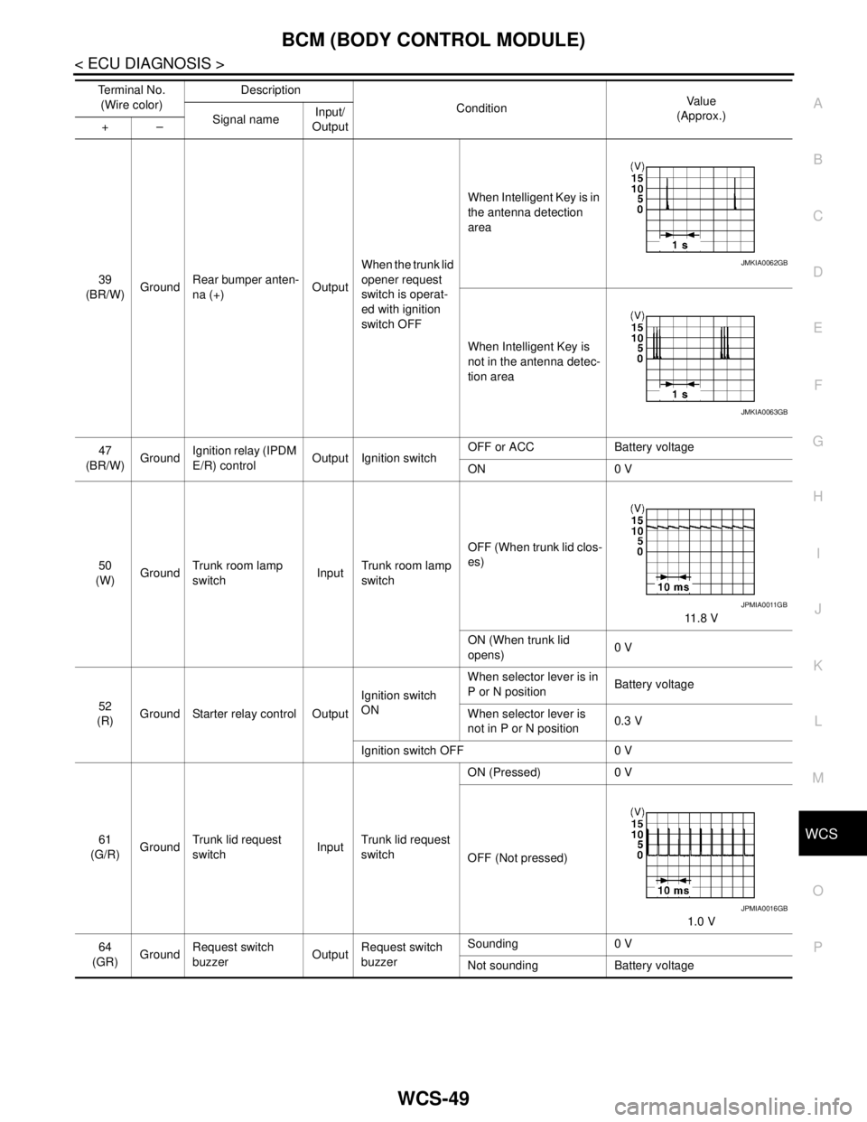
39
(BR/W)GroundRear bumper anten-
na (+)OutputWhen the trunk lid
opener request
switch is operat-
ed with ignition
switch OFFWhen Intelligent Key is in
the antenna detection
area
When Intelligent Key is
not in the antenna detec-
tion area
47
(BR/W)GroundIgnition relay (IPDM
E/R) controlOutput Ignition switchOFF or ACC Battery voltage
ON 0 V
50
(W)GroundTrunk room lamp
switchInputTrunk room lamp
switchOFF (When trunk lid clos-
es)
11.8 V
ON (When trunk lid
opens)0 V
52
(R)Ground Starter relay control OutputIgnition switch
ONWhen selector lever is in
P or N positionBattery voltage
When selector lever is
not in P or N position0.3 V
Ignition switch OFF 0 V
61
(G/R)GroundTrunk lid request
switchInputTrunk lid request
switchON (Pressed) 0 V
OFF (Not pressed)
1.0 V
64
(GR)GroundRequest switch
buzzerOutputRequest switch
buzzerSounding 0 V
Not sounding Battery voltage Te r m i n a l N o .
(Wire color)Description
ConditionVa l u e
(Approx.)
Signal nameInput/
Output +–
JMKIA0062GB
JMKIA0063GB
JPMIA0011GB
JPMIA0016GB
Page 4983 of 5121

WCS
BCM (BODY CONTROL MODULE)
WCS-53
< ECU DIAGNOSIS >
C
D
E
F
G
H
I
J
K
L
MB A
O
P
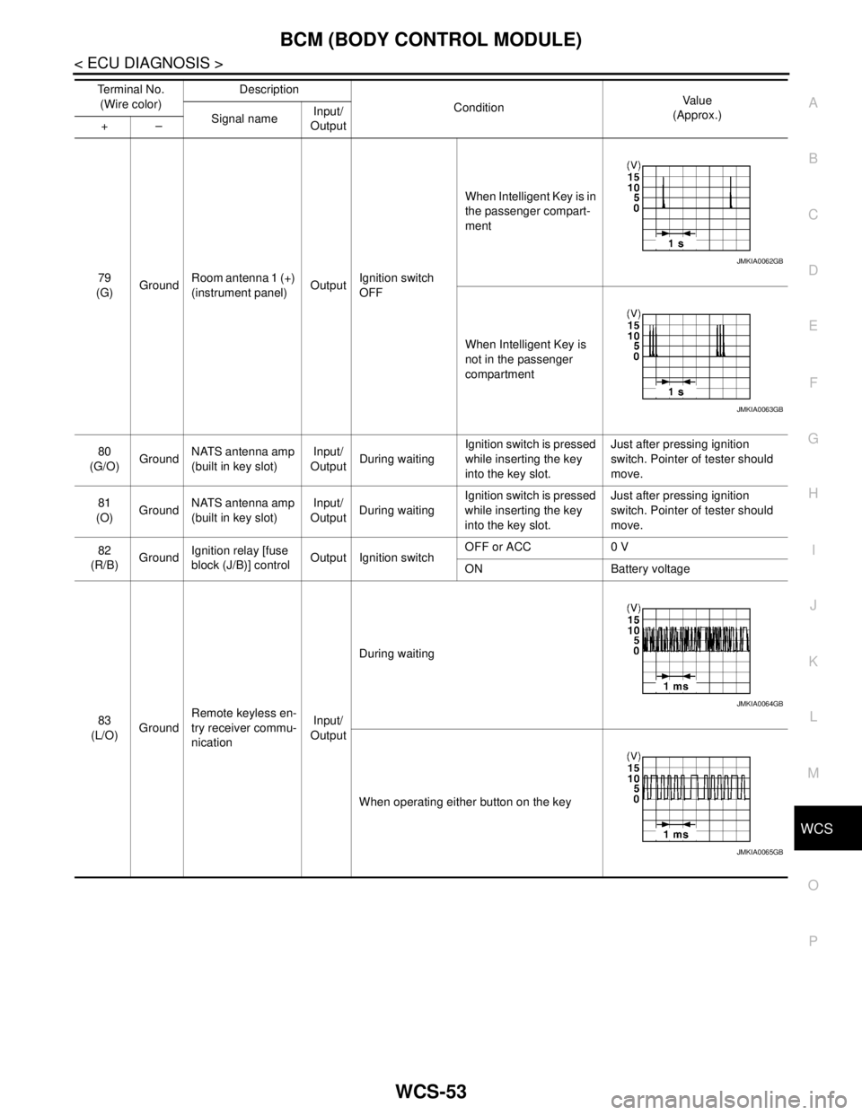
79
(G)GroundRoom antenna 1 (+)
(instrument panel)OutputIgnition switch
OFFWhen Intelligent Key is in
the passenger compart-
ment
When Intelligent Key is
not in the passenger
compartment
80
(G/O)GroundNATS antenna amp
(built in key slot)Input/
OutputDuring waitingIgnition switch is pressed
while inserting the key
into the key slot.Just after pressing ignition
switch. Pointer of tester should
move.
81
(O)GroundNATS antenna amp
(built in key slot)Input/
OutputDuring waitingIgnition switch is pressed
while inserting the key
into the key slot.Just after pressing ignition
switch. Pointer of tester should
move.
82
(R/B)GroundIgnition relay [fuse
block (J/B)] controlOutput Ignition switchOFF or ACC 0 V
ON Battery voltage
83
(L/O)GroundRemote keyless en-
try receiver commu-
nicationInput/
OutputDuring waiting
When operating either button on the key Te r m i n a l N o .
(Wire color)Description
ConditionVa l u e
(Approx.)
Signal nameInput/
Output +–
JMKIA0062GB
JMKIA0063GB
JMKIA0064GB
JMKIA0065GB
Page 4986 of 5121

WCS-56
< ECU DIAGNOSIS >
BCM (BODY CONTROL MODULE)
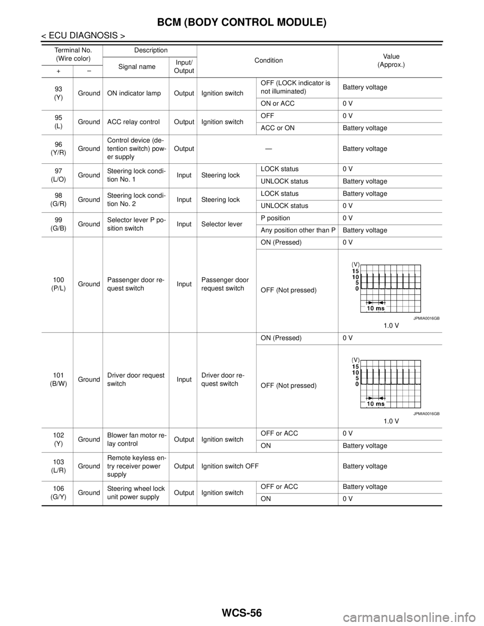
93
(Y)Ground ON indicator lamp Output Ignition switchOFF (LOCK indicator is
not illuminated)Battery voltage
ON or ACC 0 V
95
(L)Ground ACC relay control Output Ignition switchOFF 0 V
ACC or ON Battery voltage
96
(Y/R)GroundControl device (de-
tention switch) pow-
er supplyOutput — Battery voltage
97
(L/O)GroundSteering lock condi-
tion No. 1Input Steering lockLOCK status 0 V
UNLOCK status Battery voltage
98
(G/R)GroundSteering lock condi-
tion No. 2Input Steering lockLOCK status Battery voltage
UNLOCK status 0 V
99
(G/B)GroundSelector lever P po-
sition switchInput Selector leverP position 0 V
Any position other than P Battery voltage
100
(P/L)GroundPassenger door re-
quest switchInputPassenger door
request switchON (Pressed) 0 V
OFF (Not pressed)
1.0 V
101
(B/W)GroundDriver door request
switchInputDriver door re-
quest switchON (Pressed) 0 V
OFF (Not pressed)
1.0 V
102
(Y)GroundBlower fan motor re-
lay controlOutput Ignition switchOFF or ACC 0 V
ON Battery voltage
103
(L/R)GroundRemote keyless en-
try receiver power
supplyOutput Ignition switch OFF Battery voltage
106
(G/Y)GroundSteering wheel lock
unit power supplyOutput Ignition switchOFF or ACC Battery voltage
ON 0 V Te r m i n a l N o .
(Wire color)Description
ConditionVa l u e
(Approx.)
Signal nameInput/
Output +–
JPMIA0016GB
JPMIA0016GB