2008 NISSAN TEANA width
[x] Cancel search: widthPage 2022 of 5121
SERVICE DATA AND SPECIFICATIONS (SDS)
EM-147
< SERVICE DATA AND SPECIFICATIONS (SDS)
C
D
E
F
G
H
I
J
K
L
MA
EM
N
P O
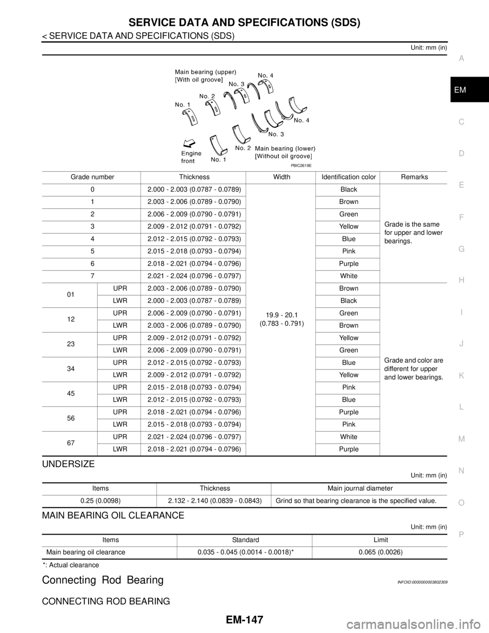
Unit: mm (in)
UNDERSIZE
Unit: mm (in)
MAIN BEARING OIL CLEARANCE
Unit: mm (in)
*: Actual clearance
Connecting Rod BearingINFOID:0000000003802309
CONNECTING ROD BEARING
Grade number Thickness Width Identification color Remarks
0 2.000 - 2.003 (0.0787 - 0.0789)
19.9 - 20.1
(0.783 - 0.791)Black
Grade is the same
for upper and lower
bearings. 1 2.003 - 2.006 (0.0789 - 0.0790) Brown
2 2.006 - 2.009 (0.0790 - 0.0791) Green
3 2.009 - 2.012 (0.0791 - 0.0792) Yellow
4 2.012 - 2.015 (0.0792 - 0.0793) Blue
5 2.015 - 2.018 (0.0793 - 0.0794) Pink
6 2.018 - 2.021 (0.0794 - 0.0796) Purple
7 2.021 - 2.024 (0.0796 - 0.0797) White
01UPR 2.003 - 2.006 (0.0789 - 0.0790) Brown
Grade and color are
different for upper
and lower bearings. LWR 2.000 - 2.003 (0.0787 - 0.0789) Black
12UPR 2.006 - 2.009 (0.0790 - 0.0791) Green
LWR 2.003 - 2.006 (0.0789 - 0.0790) Brown
23UPR 2.009 - 2.012 (0.0791 - 0.0792) Yellow
LWR 2.006 - 2.009 (0.0790 - 0.0791) Green
34UPR 2.012 - 2.015 (0.0792 - 0.0793) Blue
LWR 2.009 - 2.012 (0.0791 - 0.0792) Yellow
45UPR 2.015 - 2.018 (0.0793 - 0.0794) Pink
LWR 2.012 - 2.015 (0.0792 - 0.0793) Blue
56UPR 2.018 - 2.021 (0.0794 - 0.0796) Purple
LWR 2.015 - 2.018 (0.0793 - 0.0794) Pink
67UPR 2.021 - 2.024 (0.0796 - 0.0797) White
LWR 2.018 - 2.021 (0.0794 - 0.0796) Purple
PBIC2619E
Items Thickness Main journal diameter
0.25 (0.0098) 2.132 - 2.140 (0.0839 - 0.0843) Grind so that bearing clearance is the specified value.
Items Standard Limit
Main bearing oil clearance 0.035 - 0.045 (0.0014 - 0.0018)* 0.065 (0.0026)
Page 2472 of 5121

FUEL TANK
FL-9
< ON-VEHICLE REPAIR >
C
D
E
F
G
H
I
J
K
L
MA
FL
N
P O
FUEL TANK
Exploded ViewINFOID:0000000003793254
In regard to the notation of torque in the figure, (A) shows an ISO standard, (B) shows a conventional stan-
dard.
Removal and InstallationINFOID:0000000003793255
WARNING:
Be sure to read “General Precautions” when working on the fuel system. Refer to FL-2, "
General Pre-
cautions".
REMOVAL
Drain fuel from fuel tank if necessary. Refer to FL-5, "Removal and Installation".
Perform work on level place.
1. Perform steps 2 to 7 of “REMOVAL” in “FUEL LEVEL SENSOR UNIT, FUEL FILTER AND FUEL PUMP
ASSEMBLY” on fuel level sensor units. Refer to FL-5, "
Removal and Installation".
2. Remove center muffler. Refer to EX-5, "
Exploded View".
3. Remove fuel tank protector.
1. Clamp 2. Vent hose 3. Clamp
4. EVAP hose 5. Fuel tank 6. Fuel tank mounting band (RH)
7. Clip 8. Fuel tank protector 9. Fuel tank mounting band (LH)
10. Clamp 11. Fuel filler hose 12. Clamp
13. Fuel filler tube 14. Grommet 15. Fuel filler cap
A.The measurement of hexagonal
width across flats: 16 mm (0.63 in)B.The measurement of hexagonal
width across flats: 14 mm (0.55 in)
Refer to GI-4, "
Components" for symbols in the figure.
JPBIA2202GB
Page 2507 of 5121
GI-14
< HOW TO USE THIS MANUAL >
TIGHTENING TORQUE OF STANDARD BOLTS
TIGHTENING TORQUE OF STANDARD BOLTS
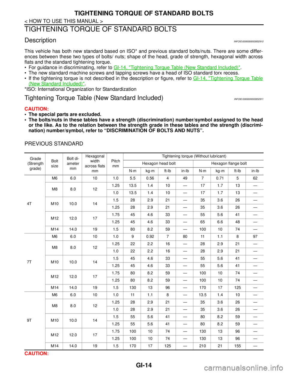
DescriptionINFOID:0000000003852910
This vehicle has both new standard based on ISO* and previous standard bolts/nuts. There are some differ-
ences between these two types of bolts/ nuts; shape of the head, grade of strength, hexagonal width across
flats and the standard tightening torque.
For guidance in discriminating, refer to GI-14, "
Tightening Torque Table (New Standard Included)".
The new standard machine screws and tapping screws have a head of ISO standard torx recess.
If the tightening torque is not described in the description or figure, refer to GI-14, "
Tightening Torque Table
(New Standard Included)".
*ISO: International Organization for Standardization
Tightening Torque Table (New Standard Included)INFOID:0000000003852911
CAUTION:
The special parts are excluded.
The bolts/nuts in these tables have a strength (discrimination) number/symbol assigned to the head
or the like. As to the relation between the strength grade in these tables and the strength (discrimi-
nation) number/symbol, refer to “DISCRIMINATION OF BOLTS AND NUTS”.
PREVIOUS STANDARD
CAUTION:
Grade
(Strength
grade)Bolt
sizeBolt di-
ameter
mmHexagonal
width
across flats
mmPitch
mmTightening torque (Without lubricant)
Hexagon head bolt Hexagon flange bolt
N·m kg-m ft-lb in-lb N·m kg-m ft-lb in-lb
4TM6 6.0 10 1.0 5.5 0.56 4 49 7 0.71 5 62
M8 8.0 121.25 13.5 1.4 10 — 17 1.7 13 —
1.0 13.5 1.4 10 — 17 1.7 13 —
M10 10.0 141.5 28 2.9 21 — 35 3.6 26 —
1.25 28 2.9 21 — 35 3.6 26 —
M12 12.0 171.75 45 4.6 33 — 55 5.6 41 —
1.25 45 4.6 33 — 65 6.6 48 —
M14 14.0 19 1.5 80 8.2 59 — 100 10 74 —
7TM6 6.0 10 1.0 9 0.92 7 80 11 1.1 8 97
M8 8.0 121.25 22 2.2 16 — 28 2.9 21 —
1.0 22 2.2 16 — 28 2.9 21 —
M10 10.0 141.5 45 4.6 33 — 55 5.6 41 —
1.25 45 4.6 33 — 55 5.6 41 —
M12 12.0 171.75 80 8.2 59 — 100 10 74 —
1.25 80 8.2 59 — 100 10 74 —
M14 14.0 19 1.5 130 13 96 — 170 17 125 —
9TM6 6.0 10 1.0 11 1.1 8 — 13.5 1.4 10 —
M8 8.0 121.25 28 2.9 21 — 35 3.6 26 —
1.0 28 2.9 21 — 35 3.6 26 —
M10 10.0 141.5 55 5.6 41 — 80 8.2 59 —
1.25 55 5.6 41 — 80 8.2 59 —
M12 12.0 171.75 100 10 74 — 130 13 96 —
1.25 100 10 74 — 130 13 96 —
M14 14.0 19 1.5 170 17 125 — 210 21 155 —
Page 2508 of 5121
TIGHTENING TORQUE OF STANDARD BOLTS
GI-15
< HOW TO USE THIS MANUAL >
C
D
E
F
G
H
I
J
K
L
MB
GI
N
O
P
The parts with aluminum or the cast iron washer surface/thread surface are excluded.
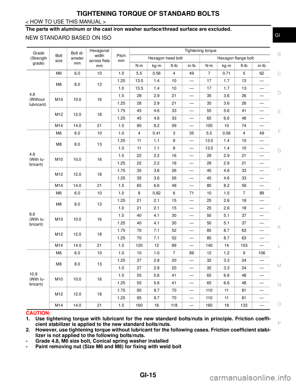
NEW STANDARD BASED ON ISO
CAUTION:
1. Use tightening torque with lubricant for the new standard bolts/nuts in principle. Friction coeffi-
cient stabilizer is applied to the new standard bolts/nuts.
2. However, use tightening torque without lubricant for the following cases. Friction coefficient stabi-
lizer is not applied to the following bolts/nuts.
- Grade 4.8, M6 size bolt, Conical spring washer installed
- Paint removing nut (Size M6 and M8) for fixing with weld bolt
Grade
(Strength
grade)Bolt
sizeBolt di-
ameter
mmHexagonal
width
across flats
mmPitch
mmTightening torque
Hexagon head bolt Hexagon flange bolt
N·m kg-m ft-lb in-lb N·m kg-m ft-lb in-lb
4.8
(Without
lubricant)M6 6.0 10 1.0 5.5 0.56 4 49 7 0.71 5 62
M8 8.0 131.25 13.5 1.4 10 — 17 1.7 13 —
1.0 13.5 1.4 10 — 17 1.7 13 —
M10 10.0 161.5 282.921 — 353.626 —
1.25 28 2.9 21 — 35 3.6 26 —
M12 12.0 181.75 45 4.6 33 — 55 5.6 41 —
1.25 45 4.6 33 — 65 6.6 48 —
M14 14.0 21 1.5 80 8.2 59 — 100 10 74 —
4.8
(With lu-
bricant)M6 6.0 10 1.0 40.413 355.50.564 49
M8 8.0 131.25 11 1.1 8 — 13.5 1.4 10 —
1.0 11 1.1 8 — 13.5 1.4 10 —
M10 10.0 161.5 222.216 — 282.921 —
1.25 22 2.2 16 — 28 2.9 21 —
M12 12.0 181.75 35 3.6 26 — 45 4.6 33 —
1.25 35 3.6 26 — 45 4.6 33 —
M14 14.0 21 1.5 65 6.6 48 — 80 8.2 59 —
8.8
(With lu-
bricant)M6 6.0 10 1.0 8 0.82 6 71 10 1.0 7 89
M8 8.0 131.25 21 2.1 15 — 25 2.6 18 —
1.0 212.115 — 252.618 —
M10 10.0 161.5 404.130 — 505.137 —
1.25 40 4.1 30 — 50 5.1 37 —
M12 12.0 181.75 70 7.1 52 — 85 8.7 63 —
1.25 70 7.1 52 — 85 8.7 63 —
M14 14.0 21 1.5 120 12 89 — 140 14 103 —
10.9
(With lu-
bricant)M6 6.0 10 1.0 10 1.0 7 89 12 1.2 9 106
M8 8.0 131.25 27 2.8 20 — 32 3.3 24 —
1.0 272.820 — 323.324 —
M10 10.0 161.5 555.641 — 656.648 —
1.25 55 5.6 41 — 65 6.6 48 —
M12 12.0 181.75 95 9.7 70 — 110 11 81 —
1.25 95 9.7 70 — 110 11 81 —
M14 14.0 21 1.5 160 16 118 — 180 18 133 —
Page 2516 of 5121
IDENTIFICATION INFORMATION
GI-23
< FEATURES OF NEW MODEL >
C
D
E
F
G
H
I
J
K
L
MB
GI
N
O
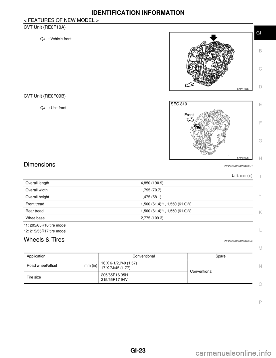
P CVT Unit (RE0F10A)
CVT Unit (RE0F09B)
DimensionsINFOID:0000000003852774
Unit: mm (in)
*1: 205/65R16 tire model
*2: 215/55R17 tire model
Wheels & TiresINFOID:0000000003852775
: Vehicle front
SAIA1496E
: Unit front
SAIA0360E
Overall length 4,850 (190.9)
Overall width 1,795 (70.7)
Overall height 1,475 (58.1)
Front tread 1,560 (61.4)*1, 1,550 (61.0)*2
Rear tread 1,560 (61.4)*1, 1,550 (61.0)*2
Wheelbase 2,775 (109.3)
Application Conventional Spare
Road wheel/offset mm (in)16 X 6-1/2J/40 (1.57)
17 X 7J/45 (1.77)
Conventional
Tire size205/65R16 95H
215/55R17 94V
Page 2561 of 5121
GW-18
< ON-VEHICLE REPAIR >
FRONT DOOR GLASS
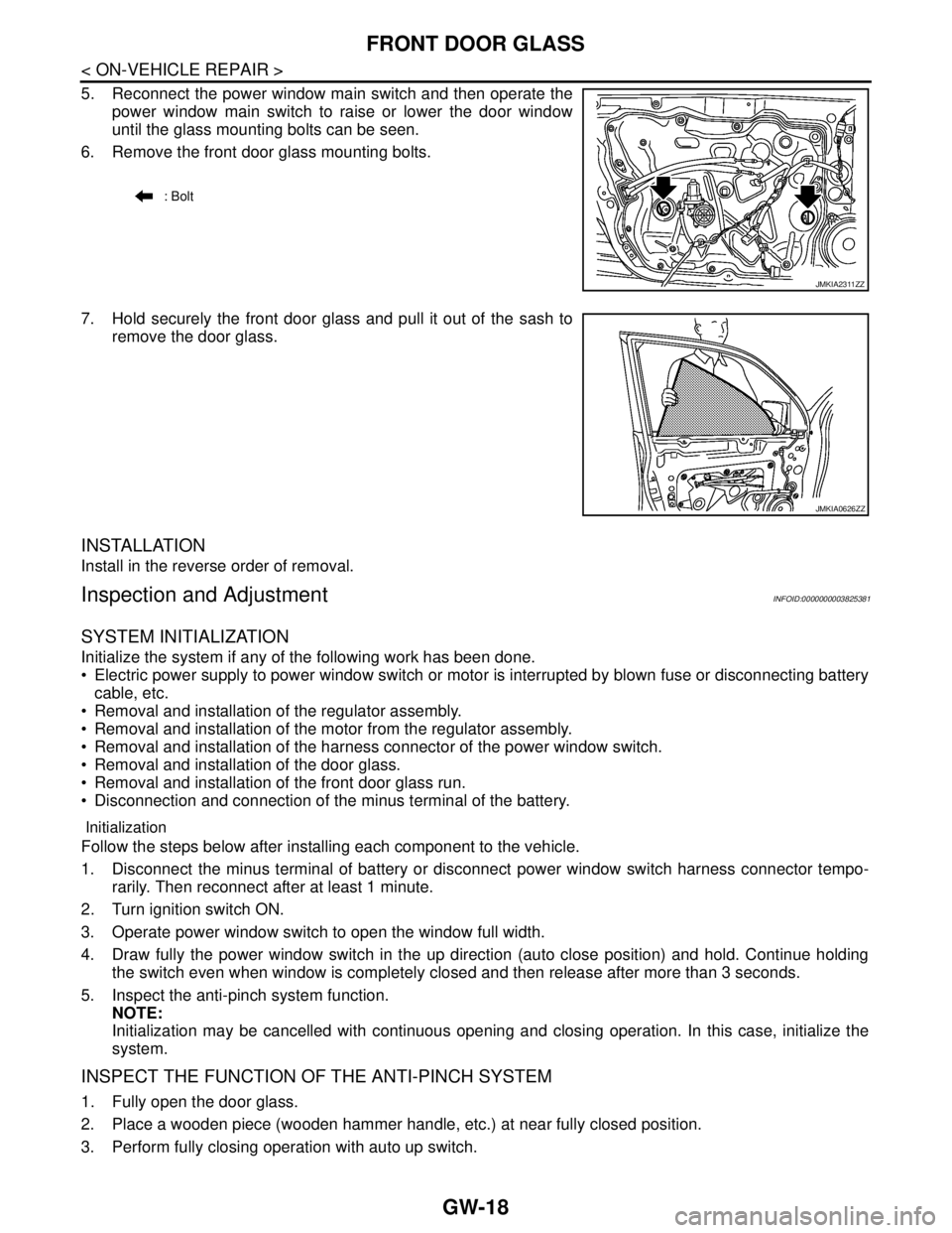
5. Reconnect the power window main switch and then operate the
power window main switch to raise or lower the door window
until the glass mounting bolts can be seen.
6. Remove the front door glass mounting bolts.
7. Hold securely the front door glass and pull it out of the sash to
remove the door glass.
INSTALLATION
Install in the reverse order of removal.
Inspection and AdjustmentINFOID:0000000003825381
SYSTEM INITIALIZATION
Initialize the system if any of the following work has been done.
Electric power supply to power window switch or motor is interrupted by blown fuse or disconnecting battery
cable, etc.
Removal and installation of the regulator assembly.
Removal and installation of the motor from the regulator assembly.
Removal and installation of the harness connector of the power window switch.
Removal and installation of the door glass.
Removal and installation of the front door glass run.
Disconnection and connection of the minus terminal of the battery.
Initialization
Follow the steps below after installing each component to the vehicle.
1. Disconnect the minus terminal of battery or disconnect power window switch harness connector tempo-
rarily. Then reconnect after at least 1 minute.
2. Turn ignition switch ON.
3. Operate power window switch to open the window full width.
4. Draw fully the power window switch in the up direction (auto close position) and hold. Continue holding
the switch even when window is completely closed and then release after more than 3 seconds.
5. Inspect the anti-pinch system function.
NOTE:
Initialization may be cancelled with continuous opening and closing operation. In this case, initialize the
system.
INSPECT THE FUNCTION OF THE ANTI-PINCH SYSTEM
1. Fully open the door glass.
2. Place a wooden piece (wooden hammer handle, etc.) at near fully closed position.
3. Perform fully closing operation with auto up switch.
: Bolt
JMKIA2311ZZ
JMKIA0626ZZ
Page 2564 of 5121
FRONT REGULATOR
GW-21
< ON-VEHICLE REPAIR >
C
D
E
F
G
H
I
J
L
MA
B
GW
N
O
P
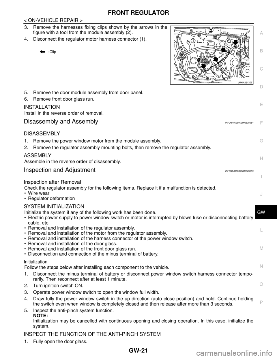
3. Remove the harnesses fixing clips shown by the arrows in the
figure with a tool from the module assembly (2).
4. Disconnect the regulator motor harness connector (1).
5. Remove the door module assembly from door panel.
6. Remove front door glass run.
INSTALLATION
Install in the reverse order of removal.
Disassembly and AssemblyINFOID:0000000003825384
DISASSEMBLY
1. Remove the power window motor from the module assembly.
2. Remove the regulator assembly mounting bolts, then remove the regulator assembly.
ASSEMBLY
Assemble in the reverse order of disassembly.
Inspection and AdjustmentINFOID:0000000003825385
Inspection after Removal
Check the regulator assembly for the following items. Replace it if a malfunction is detected.
Wire wear
Regulator deformation
SYSTEM INITIALIZATION
Initialize the system if any of the following work has been done.
Electric power supply to power window switch or motor is interrupted by blown fuse or disconnecting battery
cable, etc.
Removal and installation of the regulator assembly.
Removal and installation of the motor from the regulator assembly.
Removal and installation of the harness connector of the power window switch.
Removal and installation of the door glass.
Removal and installation of the front door glass run.
Disconnection and connection of the minus terminal of battery.
Initialization
Follow the steps below after installing each component to the vehicle.
1. Disconnect the minus terminal of battery or disconnect power window switch harness connector tempo-
rarily. Then reconnect after at least 1 minute.
2. Turn ignition switch ON.
3. Operate power window switch to open the window full width.
4. Draw fully the power window switch in the up direction (auto close position) and hold. Continue holding
the switch even when window is completely closed and then release after more than 3 seconds.
5. Inspect the anti-pinch system function.
NOTE:
Initialization may be cancelled with continuous opening and closing operation. In this case, initialize the
system.
INSPECT THE FUNCTION OF THE ANTI-PINCH SYSTEM
1. Fully open the door glass.
: Clip
JMKIA2313ZZ
Page 4492 of 5121
![NISSAN TEANA 2008 Service Manual MECHANICAL SYSTEM
TM-19
< FUNCTION DIAGNOSIS >[CVT: RE0F09B]
C
E
F
G
H
I
J
K
L
MA
B
TM
N
O
P
CVT fluid temperature sensor
Secondary pressure sensor
ROM assembly
Component DescriptionINFOID:00000 NISSAN TEANA 2008 Service Manual MECHANICAL SYSTEM
TM-19
< FUNCTION DIAGNOSIS >[CVT: RE0F09B]
C
E
F
G
H
I
J
K
L
MA
B
TM
N
O
P
CVT fluid temperature sensor
Secondary pressure sensor
ROM assembly
Component DescriptionINFOID:00000](/manual-img/5/57391/w960_57391-4491.png)
MECHANICAL SYSTEM
TM-19
< FUNCTION DIAGNOSIS >[CVT: RE0F09B]
C
E
F
G
H
I
J
K
L
MA
B
TM
N
O
P
CVT fluid temperature sensor
Secondary pressure sensor
ROM assembly
Component DescriptionINFOID:0000000003848923
Item Function
Torque converterThe torque converter is the device that increases the engine torque as well as the con-
ventional AT and transmits it to the transaxle.
Oil pumpThe adoption of a trochoidal oil pump with a flow control valve actuated directly by the
engine enables the sufficient discharge from an oil pump in the low-rpm range and the
adequate discharge adjustments in the high-rpm range.
Planetary gear
Perform the transmission of drive power and the switching of forward/backward move-
ment. Forward clutch
Reverse brake
Primary pulley It is composed of a pair of pulleys (the groove width is changed freely in the axial direc-
tion) and the steel belt (the steel star wheels are placed continuously and the belt is guid-
ed with the multilayer steel rings on both sides). The groove width changes according to
wrapping radius of steel belt and pulley from low status to overdrive status continuously
with non-step. It is controlled with the oil pressures of primary pulley and secondary pul-
ley. Secondary pulley
Steel belt
Output gear
Reduction gear consists of primary deceleration (output gear and idler gear in pair) and
secondary deceleration (reduction gear and final gear in pair). Each of them uses a he-
lical gear. Idler gear
Reduction gear
Final gear
Differential
Manual shaft
The parking rod rotates the parking pole and the parking pole engages with the parking
gear when the manual shaft is in “P” position. As a result the parking gear and the output
axis are fixed. Parking rod
Parking pawl
Parking gear