2008 NISSAN TEANA width
[x] Cancel search: widthPage 1578 of 5121
![NISSAN TEANA 2008 Service Manual ON BOARD DIAGNOSTIC (OBD) SYSTEM
EC-117
< FUNCTION DIAGNOSIS >[VQ25DE, VQ35DE]
C
D
E
F
G
H
I
J
K
L
MA
EC
N
P O
COOLAN TEMP/S°C or °F The engine coolant temperature (determined by
the signal voltag NISSAN TEANA 2008 Service Manual ON BOARD DIAGNOSTIC (OBD) SYSTEM
EC-117
< FUNCTION DIAGNOSIS >[VQ25DE, VQ35DE]
C
D
E
F
G
H
I
J
K
L
MA
EC
N
P O
COOLAN TEMP/S°C or °F The engine coolant temperature (determined by
the signal voltag](/manual-img/5/57391/w960_57391-1577.png)
ON BOARD DIAGNOSTIC (OBD) SYSTEM
EC-117
< FUNCTION DIAGNOSIS >[VQ25DE, VQ35DE]
C
D
E
F
G
H
I
J
K
L
MA
EC
N
P O
COOLAN TEMP/S°C or °F The engine coolant temperature (determined by
the signal voltage of the engine coolant tempera-
ture sensor) is displayed. When the engine coolant temperature
sensor is open or short-circuited,
ECM enters fail-safe mode. The en-
gine coolant temperature determined
by the ECM is displayed.
A/F SEN1 (B1)
V The A/F signal computed from the input signal of
the air fuel ratio (A/F) sensor 1 is displayed.
A/F SEN1 (B2)
HO2S2 (B1)
V The signal voltage of the heated oxygen sensor 2
is displayed.
HO2S2 (B2)
HO2S2 MNTR(B1)
RICH/LEAN Display of heated oxygen sensor 2 signal:
RICH: means the amount of oxygen after three
way catalyst is relatively small.
LEAN: means the amount of oxygen after three
way catalyst is relatively large. When the engine is stopped, a certain
value is indicated.
HO2S2 MNTR(B2)
VHCL SPEED SE km/h or mph The vehicle speed computed from the vehicle
speed signal sent from combination meter is dis-
played.
BATTERY VOLT V The power supply voltage of ECM is displayed.
ACCEL SEN 1
V The accelerator pedal position sensor signal volt-
age is displayed. ACCEL SEN 2 signal is converted by
ECM internally. Thus, it differs from
ECM terminal voltage signal. ACCEL SEN 2
TP SEN 1-B1
V The throttle position sensor signal voltage is dis-
played. TP SEN 2-B1 signal is converted by
ECM internally. Thus, it differs from
ECM terminal voltage signal. TP SEN 2-B1
INT/A TEMP SE°C or °F The intake air temperature (determined by the
signal voltage of the intake air temperature sen-
sor) is indicated.
START SIGNAL ON/OFF Indicates start signal status [ON/OFF] computed
by the ECM according to the signals of engine
speed and battery voltage. After starting the engine, [OFF] is dis-
played regardless of the starter sig-
nal.
CLSD THL POS ON/OFF Indicates idle position [ON/OFF] computed by
ECM according to the accelerator pedal position
sensor signal.
AIR COND SIG ON/OFF Indicates [ON/OFF] condition of the air condition-
er switch as determined by the air conditioner sig-
nal.
P/N POSI SW ON/OFF Indicates [ON/OFF] condition from the park/neu-
tral position (PNP) signal.
PW/ST SIGNAL ON/OFF [ON/OFF] condition of the power steering system
(determined by the signal voltage of the power
steering pressure sensor) is indicated.
LOAD SIGNAL ON/OFF Indicates [ON/OFF] condition from the electrical
load signal.
ON: Rear window defogger switch is ON and/or
lighting switch is in 2nd position.
OFF: Both rear window defogger switch and light-
ing switch are OFF.
IGNITION SW ON/OFF Indicates [ON/OFF] condition from ignition switch
signal.
HEATER FAN SW ON/OFF Indicates [ON/OFF] condition from the heater fan
switch signal.
BRAKE SW ON/OFF Indicates [ON/OFF] condition from the stop lamp
switch signal.
INJ PULSE-B1
msec Indicates the actual fuel injection pulse width
compensated by ECM according to the input sig-
nals. When the engine is stopped, a certain
computed value is indicated.
INJ PULSE-B2Monitored item Unit Description Remarks
Page 1585 of 5121
![NISSAN TEANA 2008 Service Manual EC-124
< COMPONENT DIAGNOSIS >[VQ25DE, VQ35DE]
TROUBLE DIAGNOSIS - SPECIFICATION VALUE
COMPONENT DIAGNOSIS
TROUBLE DIAGNOSIS - SPECIFICATION VALUE
DescriptionINFOID:0000000003856505
The specification NISSAN TEANA 2008 Service Manual EC-124
< COMPONENT DIAGNOSIS >[VQ25DE, VQ35DE]
TROUBLE DIAGNOSIS - SPECIFICATION VALUE
COMPONENT DIAGNOSIS
TROUBLE DIAGNOSIS - SPECIFICATION VALUE
DescriptionINFOID:0000000003856505
The specification](/manual-img/5/57391/w960_57391-1584.png)
EC-124
< COMPONENT DIAGNOSIS >[VQ25DE, VQ35DE]
TROUBLE DIAGNOSIS - SPECIFICATION VALUE
COMPONENT DIAGNOSIS
TROUBLE DIAGNOSIS - SPECIFICATION VALUE
DescriptionINFOID:0000000003856505
The specification (SP) value indicates the tolerance of the value that is displayed in “SPEC” of “DATA MONI-
TOR” mode of CONSULT-III during normal operation of the Engine Control System. When the value in “SPEC”
in “DATA MONITOR” mode is NOT within the SP value, the Engine Control System may have one or more
malfunctions.
The SP value is used to detect malfunctions that may affect the Engine Control System, but will not illuminate
the MI.
The SP value will be displayed for the following three items:
B/FUEL SCHDL (The fuel injection pulse width programmed into ECM prior to any learned on board correc-
tion)
A/F ALPHA-B1/B2 (The mean value of air-fuel ratio feedback correction factor per cycle)
MAS A/F SE-B1 (The signal voltage of the mass air flow sensor)
Component Function CheckINFOID:0000000003856506
1.START
Check that all of the following conditions are satisfied.
Vehicle driven distance: More than 5,000 km (3,107 miles)
Barometric pressure: 98.3 - 104.3 kPa (0.983 - 1.043 bar, 1.003 - 1.064 kg/cm
2, 14.25 - 15.12 psi)
Atmospheric temperature: 20 - 30°C (68 - 86°F)
Engine coolant temperature: 75 - 95°C (167 - 203°F)
Transmission: Warmed-up
- After the engine is warmed up to normal operating temperature, drive vehicle until “FLUID TEMP SE” (CVT
fluid temperature sensor signal) indicates more than 60°C (140°F).
Electrical load: Not applied
- Rear window defogger switch, air conditioner switch, lighting switch are OFF. Steering wheel is straight
ahead.
Engine speed: Idle
>> GO TO 2.
2.PERFORM “SPEC” OF “DATA MONITOR” MODE
With CONSULT-III
NOTE:
Perform “SPEC” in “DATA MONITOR” mode in maximum scale display.
1. Perform “EC-11, "
BASIC INSPECTION : Special Repair Requirement".
2. Select “B/FUEL SCHDL”, “A/F ALPHA-B1”, “A/F ALPHA-B2” and “MAS A/F SE-B1” in “SPEC” of “DATA
MONITOR” mode with CONSULT-III.
3. Check that monitor items are within the SP value.
Is the measurement value within the SP value?
YES >> INSPECTION END
NO >> Go to EC-125, "
Diagnosis Procedure".
Page 1607 of 5121
![NISSAN TEANA 2008 Service Manual EC-146
< COMPONENT DIAGNOSIS >[VQ25DE, VQ35DE]
P0075, P0081 IVT CONTROL SOLENOID VALVE
P0075, P0081 IVT CONTROL SOLENOID VALVE
DescriptionINFOID:0000000003856523
Intake valve timing control solenoid v NISSAN TEANA 2008 Service Manual EC-146
< COMPONENT DIAGNOSIS >[VQ25DE, VQ35DE]
P0075, P0081 IVT CONTROL SOLENOID VALVE
P0075, P0081 IVT CONTROL SOLENOID VALVE
DescriptionINFOID:0000000003856523
Intake valve timing control solenoid v](/manual-img/5/57391/w960_57391-1606.png)
EC-146
< COMPONENT DIAGNOSIS >[VQ25DE, VQ35DE]
P0075, P0081 IVT CONTROL SOLENOID VALVE
P0075, P0081 IVT CONTROL SOLENOID VALVE
DescriptionINFOID:0000000003856523
Intake valve timing control solenoid valve is activated by ON/OFF
pulse duty (ratio) signals from the ECM.
The intake valve timing control solenoid valve changes the oil
amount and direction of flow through intake valve timing control unit
or stops oil flow.
The longer pulse width advances valve angle.
The shorter pulse width retards valve angle.
When ON and OFF pulse widths become equal, the solenoid valve
stops oil pressure flow to fix the intake valve angle at the control
position.
DTC LogicINFOID:0000000003856524
DTC DETECTION LOGIC
DTC CONFIRMATION PROCEDURE
1.PRECONDITIONING
If DTC Confirmation Procedure has been previously conducted, always turn ignition switch OFF and wait at
least 10 seconds before conducting the next test.
>> GO TO 2.
2.PERFORM DTC CONFIRMATION PROCEDURE
1. Start engine and let it idle for 5 seconds.
2. Check 1st trip DTC.
Is 1st trip DTC detected?
YES >> Go to EC-146, "Diagnosis Procedure".
NO >> INSPECTION END
Diagnosis ProcedureINFOID:0000000003856525
1.CHECK INTAKE VALVE TIMING CONTROL SOLENOID VALVE POWER SUPPLY CIRCUIT
1. Turn ignition switch OFF.
2. Disconnect intake valve timing control solenoid valve harness connector.
3. Turn ignition switch ON.
4. Check the voltage between intake valve timing (IVT) control solenoid valve harness connector and ground
with CONSULT-III or tester.
Is the inspection result normal?
YES >> GO TO 2.
PBIB1842E
DTC No. Trouble diagnosis name DTC detecting condition Possible cause
P0075Intake valve timing control so-
lenoid valve (bank 1) circuitAn improper voltage is sent to the ECM
through intake valve timing control solenoid
valve. Harness or connectors
(Intake valve timing control solenoid valve
circuit is open or shorted.)
Intake valve timing control solenoid valve P0081Intake valve timing control so-
lenoid valve (bank 2) circuit
DTCIVT control solenoid valve
Ground Voltage
Bank Connector Terminal
P0075 1 F81 2
Ground Battery voltage
P0081 2 F82 2
Page 1884 of 5121
PREPARATION
EM-9
< PREPARATION >
C
D
E
F
G
H
I
J
K
L
MA
EM
N
P O
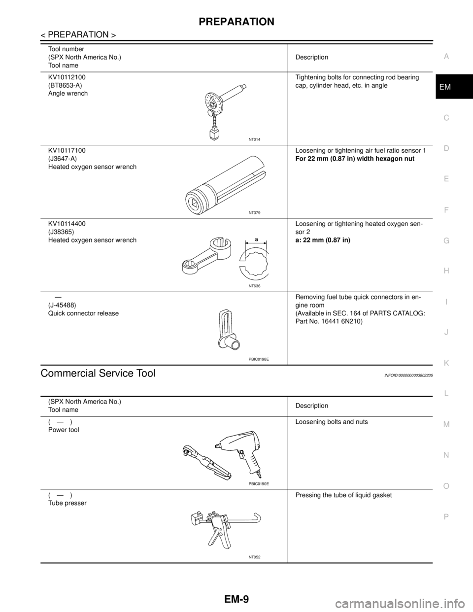
Commercial Service ToolINFOID:0000000003802235
KV10112100
(BT8653-A)
Angle wrenchTightening bolts for connecting rod bearing
cap, cylinder head, etc. in angle
KV10117100
(J3647-A)
Heated oxygen sensor wrenchLoosening or tightening air fuel ratio sensor 1
For 22 mm (0.87 in) width hexagon nut
KV10114400
(J38365)
Heated oxygen sensor wrenchLoosening or tightening heated oxygen sen-
sor 2
a: 22 mm (0.87 in)
—
(J-45488)
Quick connector releaseRemoving fuel tube quick connectors in en-
gine room
(Available in SEC. 164 of PARTS CATALOG:
Part No. 16441 6N210) Tool number
(SPX North America No.)
Tool nameDescription
NT014
NT379
NT636
PBIC0198E
(SPX North America No.)
Tool nameDescription
(—)
Power toolLoosening bolts and nuts
(—)
Tube presserPressing the tube of liquid gasket
PBIC0190E
NT052
Page 2001 of 5121
EM-126
< DISASSEMBLY AND ASSEMBLY >
CYLINDER BLOCK
If the calculated value exceeds the limit, select proper connecting rod bearing according to connecting rod
big end diameter and crankshaft pin journal diameter to obtain the specified bearing oil clearance. Refer to
EM-130, "
ConnectingRodBearing".
Method of Using Plastigage
Remove oil and dust on crankshaft pin journal and the surfaces of each bearing completely.
Cut a plastigage slightly shorter than the bearing width, and place it in crankshaft axial direction, avoiding oil
holes.
Install connecting rod bearings to connecting rod and connecting rod bearing cap, and tighten connecting
rod bolts to the specified torque. Refer to EM-110, "
Disassembly and Assembly" for the tightening proce-
dure.
CAUTION:
Never rotate crankshaft.
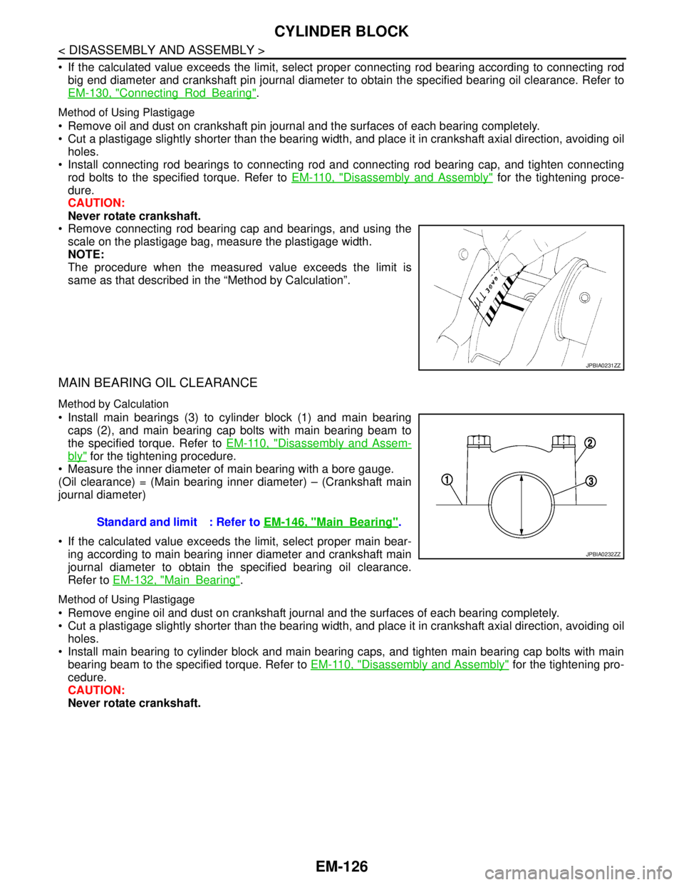
Remove connecting rod bearing cap and bearings, and using the
scale on the plastigage bag, measure the plastigage width.
NOTE:
The procedure when the measured value exceeds the limit is
same as that described in the “Method by Calculation”.
MAIN BEARING OIL CLEARANCE
Method by Calculation
Install main bearings (3) to cylinder block (1) and main bearing
caps (2), and main bearing cap bolts with main bearing beam to
the specified torque. Refer to EM-110, "
Disassembly and Assem-
bly" for the tightening procedure.
Measure the inner diameter of main bearing with a bore gauge.
(Oil clearance) = (Main bearing inner diameter) – (Crankshaft main
journal diameter)
If the calculated value exceeds the limit, select proper main bear-
ing according to main bearing inner diameter and crankshaft main
journal diameter to obtain the specified bearing oil clearance.
Refer to EM-132, "
MainBearing".
Method of Using Plastigage
Remove engine oil and dust on crankshaft journal and the surfaces of each bearing completely.
Cut a plastigage slightly shorter than the bearing width, and place it in crankshaft axial direction, avoiding oil
holes.
Install main bearing to cylinder block and main bearing caps, and tighten main bearing cap bolts with main
bearing beam to the specified torque. Refer to EM-110, "
Disassembly and Assembly" for the tightening pro-
cedure.
CAUTION:
Never rotate crankshaft.
JPBIA0231ZZ
Standard and limit : Refer to EM-146, "MainBearing".
JPBIA0232ZZ
Page 2002 of 5121
CYLINDER BLOCK
EM-127
< DISASSEMBLY AND ASSEMBLY >
C
D
E
F
G
H
I
J
K
L
MA
EM
N
P O
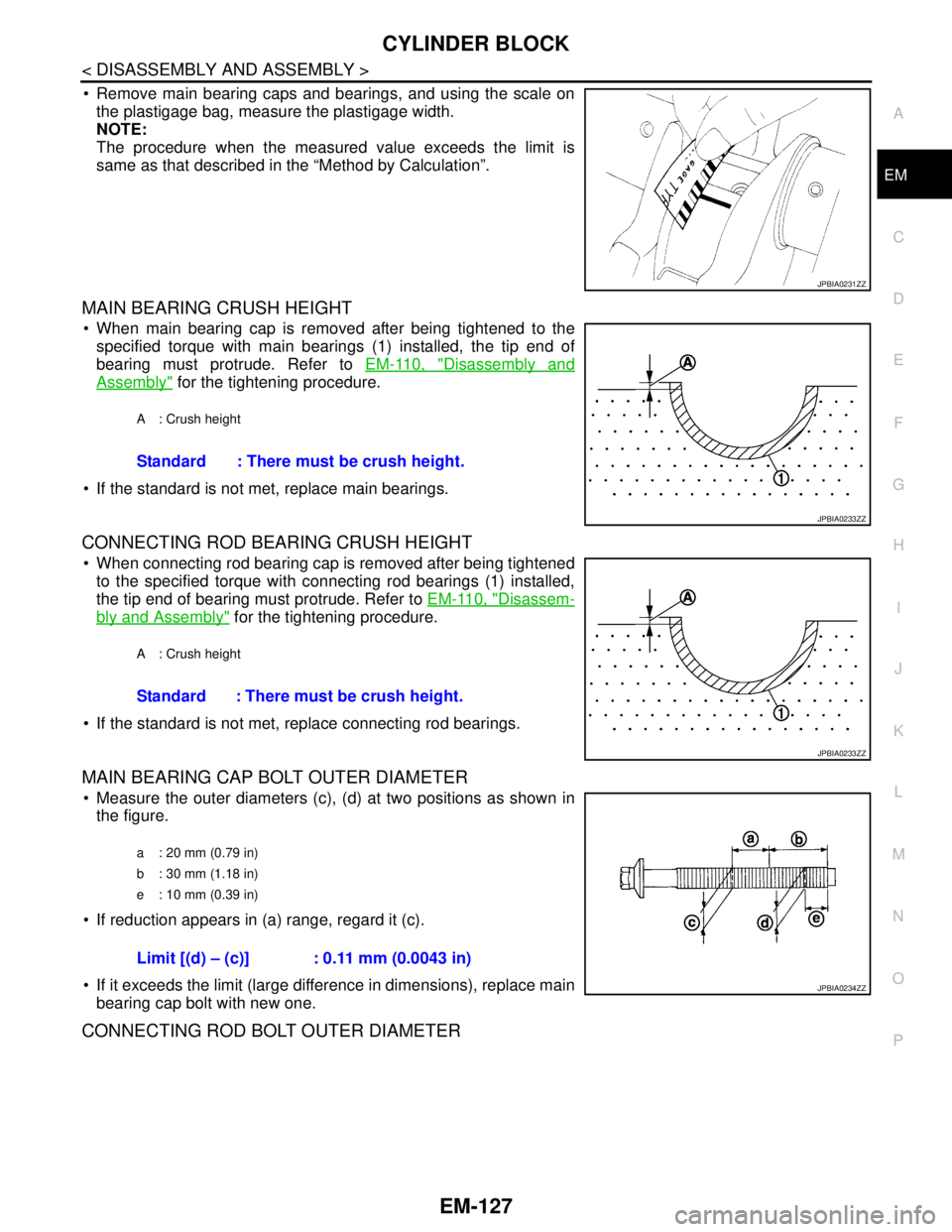
Remove main bearing caps and bearings, and using the scale on
the plastigage bag, measure the plastigage width.
NOTE:
The procedure when the measured value exceeds the limit is
same as that described in the “Method by Calculation”.
MAIN BEARING CRUSH HEIGHT
When main bearing cap is removed after being tightened to the
specified torque with main bearings (1) installed, the tip end of
bearing must protrude. Refer to EM-110, "
Disassembly and
Assembly" for the tightening procedure.
If the standard is not met, replace main bearings.
CONNECTING ROD BEARING CRUSH HEIGHT
When connecting rod bearing cap is removed after being tightened
to the specified torque with connecting rod bearings (1) installed,
the tip end of bearing must protrude. Refer to EM-110, "
Disassem-
bly and Assembly" for the tightening procedure.
If the standard is not met, replace connecting rod bearings.
MAIN BEARING CAP BOLT OUTER DIAMETER
Measure the outer diameters (c), (d) at two positions as shown in
the figure.
If reduction appears in (a) range, regard it (c).
If it exceeds the limit (large difference in dimensions), replace main
bearing cap bolt with new one.
CONNECTING ROD BOLT OUTER DIAMETER
JPBIA0231ZZ
A : Crush height
Standard : There must be crush height.
JPBIA0233ZZ
A : Crush height
Standard : There must be crush height.
JPBIA0233ZZ
a : 20 mm (0.79 in)
b : 30 mm (1.18 in)
e : 10 mm (0.39 in)
Limit [(d) – (c)] : 0.11 mm (0.0043 in)
JPBIA0234ZZ
Page 2016 of 5121
SERVICE DATA AND SPECIFICATIONS (SDS)
EM-141
< SERVICE DATA AND SPECIFICATIONS (SDS)
C
D
E
F
G
H
I
J
K
L
MA
EM
N
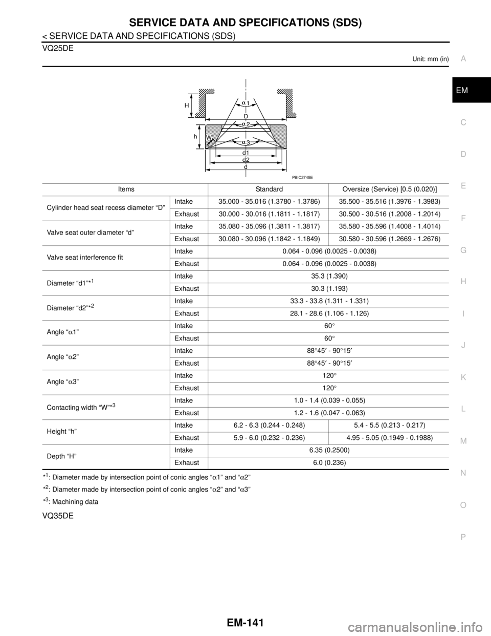
P O VQ25DE
Unit: mm (in)
*1: Diameter made by intersection point of conic angles “α1” and “α2”
*
2: Diameter made by intersection point of conic angles “α2” and “α3”
*
3: Machining data
VQ35DE
Items Standard Oversize (Service) [0.5 (0.020)]
Cylinder head seat recess diameter “D”Intake 35.000 - 35.016 (1.3780 - 1.3786) 35.500 - 35.516 (1.3976 - 1.3983)
Exhaust 30.000 - 30.016 (1.1811 - 1.1817) 30.500 - 30.516 (1.2008 - 1.2014)
Valve seat outer diameter “d”Intake 35.080 - 35.096 (1.3811 - 1.3817) 35.580 - 35.596 (1.4008 - 1.4014)
Exhaust 30.080 - 30.096 (1.1842 - 1.1849) 30.580 - 30.596 (1.2669 - 1.2676)
Valve seat interference fitIntake 0.064 - 0.096 (0.0025 - 0.0038)
Exhaust 0.064 - 0.096 (0.0025 - 0.0038)
Diameter “d1”*
1Intake 35.3 (1.390)
Exhaust 30.3 (1.193)
Diameter “d2”*
2Intake 33.3 - 33.8 (1.311 - 1.331)
Exhaust 28.1 - 28.6 (1.106 - 1.126)
Angle “α1”Intake 60°
Exhaust 60°
Angle “α2”Intake 88°45′ - 90°15′
Exhaust 88°45′ - 90°15′
Angle “α3”Intake 120°
Exhaust 120°
Contacting width “W”*
3Intake 1.0 - 1.4 (0.039 - 0.055)
Exhaust 1.2 - 1.6 (0.047 - 0.063)
Height “h”Intake 6.2 - 6.3 (0.244 - 0.248) 5.4 - 5.5 (0.213 - 0.217)
Exhaust 5.9 - 6.0 (0.232 - 0.236) 4.95 - 5.05 (0.1949 - 0.1988)
Depth “H”Intake 6.35 (0.2500)
Exhaust 6.0 (0.236)
PBIC2745E
Page 2017 of 5121
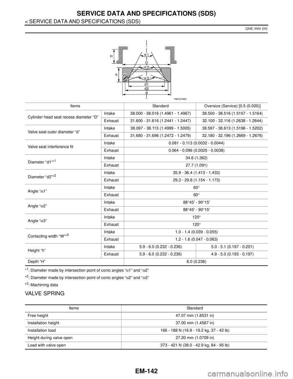
EM-142
< SERVICE DATA AND SPECIFICATIONS (SDS)
SERVICE DATA AND SPECIFICATIONS (SDS)
Unit: mm (in)
*1: Diameter made by intersection point of conic angles “α1” and “α2”
*
2: Diameter made by intersection point of conic angles “α2” and “α3”
*
3: Machining data
VALVE SPRING
Items Standard Oversize (Service) [0.5 (0.020)]
Cylinder head seat recess diameter “D”Intake 38.000 - 38.016 (1.4961 - 1.4967) 38.500 - 38.516 (1.5157 - 1.5164)
Exhaust 31.600 - 31.616 (1.2441 - 1.2447) 32.100 - 32.116 (1.2638 - 1.2644)
Valve seat outer diameter “d”Intake 38.097 - 38.113 (1.4999 - 1.5005) 38.597 - 38.613 (1.5196 - 1.5202)
Exhaust 31.680 - 31.696 (1.2472 - 1.2479) 32.180 - 32.196 (1.2669 - 1.2676)
Valve seat interference fitIntake 0.081 - 0.113 (0.0032 - 0.0044)
Exhaust 0.064 - 0.096 (0.0025 - 0.0038)
Diameter “d1”*
1Intake 34.6 (1.362)
Exhaust 27.7 (1.091)
Diameter “d2”*
2Intake 35.9 - 36.4 (1.413 - 1.433)
Exhaust 29.3 - 29.8 (1.154 - 1.173)
Angle “α1”Intake 60°
Exhaust 60°
Angle “α2”Intake 88°45′ - 90°15′
Exhaust 88°45′ - 90°15′
Angle “α3”Intake 120°
Exhaust 120°
Contacting width “W”*
3Intake 1.0 - 1.4 (0.039 - 0.055)
Exhaust 1.2 - 1.6 (0.047 - 0.063)
Height “h”Intake 5.9 - 6.0 (0.232 - 0.236) 5.0 - 5.1 (0.197 - 0.201)
Exhaust 5.9 - 6.0 (0.232 - 0.236) 4.9 - 5.0 (0.193 - 0.197)
Depth “H”6.0 (0.236)
PBIC2745E
Items Standard
Free height 47.07 mm (1.8531 in)
Installation height 37.00 mm (1.4567 in)
Installation load 166 - 188 N (16.9 - 19.2 kg, 37 - 42 lb)
Height during valve open 27.20 mm (1.0709 in)
Load with valve open 373 - 421 N (38.0 - 42.9 kg, 84 - 95 lb)