Page 4398 of 5121
ST-8
< ON-VEHICLE MAINTENANCE >
POWER STEERING FLUID
3. Repeat step 2 above several times at approximately 3 second intervals.
CAUTION:
Never hold the steering wheel in a locked position for more than 10 seconds. (There is the possi-
bility that oil pump may be damaged.)
4. Check fluid for bubbles and white contamination.
5. Stop the engine if bubbles and white contamination do not drain out. Perform step 2 and 3 above after
waiting until bubbles and white contamination drain out.
6. Stop the engine, and then check fluid level.
Page 4399 of 5121

STEERING WHEEL
ST-9
< ON-VEHICLE MAINTENANCE >
C
D
E
F
H
I
J
K
L
MA
B
ST
N
O
P
STEERING WHEEL
InspectionINFOID:0000000003806313
STEERING WHEEL AXIAL END PLAY
1. Check installation conditions of steering gear assembly, front suspension assembly, axle and steering col-
umn assembly.
2. Check if movement exists when steering wheel is moved up and down, to the left and right and to the axial
direction.
3. Check the following items when steering wheel axial end play is out of the standard.
Check the steering column assembly mounting condition. Refer to ST-13, "
Exploded View".
Check steering gear assembly mounting condition for looseness. Refer to ST-18, "
Exploded View".
STEERING WHEEL PLAY
1. Turn steering wheel so that front wheels come to the straight-ahead position.
2. Start the engine and lightly turn steering wheel to the left and right until front wheels start to move.
3. Measure steering wheel movement on the outer circumference.
4. Check the following items when steering wheel play is out of the standard.
Check backlash for each joint of steering column assembly.
Check installation condition of steering gear assembly.
NEUTRAL POSITION STEERING WHEEL
1. Check that steering gear assembly, steering column assembly and steering wheel are installed in the cor-
rect position.
2. Perform neutral position inspection after wheel alignment. Refer to FSU-7, "
Wheel Alignment Inspection".
3. Set the vehicle to the straight-ahead position and confirm steering wheel is in the neutral position.
4. Loosen outer socket lock nut and turn inner socket to left and right equally to make fine adjustments if
steering wheel is not in the neutral position.
STEERING WHEEL TURNING FORCE
1. Park the vehicle on a level and dry surface, set parking brake.
2. Tires need to be inflated normal pressure. Refer to WT-5, "
Tire Air Pressure".
3. Start the engine.
4. Bring power steering fluid up to adequate operating temperature.Standard
Steering wheel axial end
play: Refer to ST-37, "
Steering
Wheel Axial End Play and
Play".
Standard
Steering wheel play : Refer to ST-37, "
Steering
Wheel Axial End Play and
Play".
Fluid temperature : 50 – 80°C (122 – 176°F)
Page 4408 of 5121
ST-18
< ON-VEHICLE REPAIR >
STEERING GEAR AND LINKAGE
STEERING GEAR AND LINKAGE
Exploded ViewINFOID:0000000003806322
REMOVAL
DISASSEMBLY
1. Steering gear assembly 2. cotter pin
: Vehicle front
Refer to GI-4, "
Components" for symbols in the figure.
JSGIA0394GB
1. Low pressure piping 2. Rear cover cap 3. Gear-sub assembly
4. Power steering solenoid valve 5. O-ring 6. Adjusting screw
7. Spring 8. Retainer 9. Outer socket
JSGIA0396GB
Page 4409 of 5121

STEERING GEAR AND LINKAGE
ST-19
< ON-VEHICLE REPAIR >
C
D
E
F
H
I
J
K
L
MA
B
ST
N
O
P
Removal and InstallationINFOID:0000000003806323
REMOVAL
1. Set the vehicle to the straight-ahead position.
2. Remove front tires.
3. Remove splash guards (RH and LH). Refer to EXT-22, "
FENDER PROTECTOR : Exploded View".
4. Remove engine under cover. Refer to EXT-28, "
Exploded View".
5. Remove heat insulator from front floor.
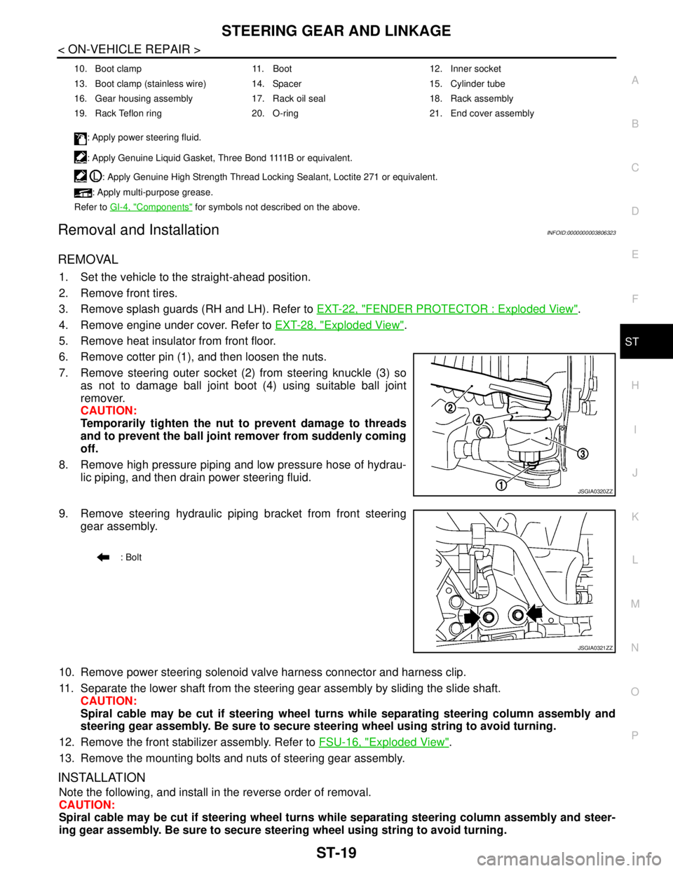
6. Remove cotter pin (1), and then loosen the nuts.
7. Remove steering outer socket (2) from steering knuckle (3) so
as not to damage ball joint boot (4) using suitable ball joint
remover.
CAUTION:
Temporarily tighten the nut to prevent damage to threads
and to prevent the ball joint remover from suddenly coming
off.
8. Remove high pressure piping and low pressure hose of hydrau-
lic piping, and then drain power steering fluid.
9. Remove steering hydraulic piping bracket from front steering
gear assembly.
10. Remove power steering solenoid valve harness connector and harness clip.
11. Separate the lower shaft from the steering gear assembly by sliding the slide shaft.
CAUTION:
Spiral cable may be cut if steering wheel turns while separating steering column assembly and
steering gear assembly. Be sure to secure steering wheel using string to avoid turning.
12. Remove the front stabilizer assembly. Refer to FSU-16, "
Exploded View".
13. Remove the mounting bolts and nuts of steering gear assembly.
INSTALLATION
Note the following, and install in the reverse order of removal.
CAUTION:
Spiral cable may be cut if steering wheel turns while separating steering column assembly and steer-
ing gear assembly. Be sure to secure steering wheel using string to avoid turning.
10. Boot clamp 11. Boot 12. Inner socket
13. Boot clamp (stainless wire) 14. Spacer 15. Cylinder tube
16. Gear housing assembly 17. Rack oil seal 18. Rack assembly
19. Rack Teflon ring 20. O-ring 21. End cover assembly
: Apply power steering fluid.
: A p p l y G e n u i n e L i q u i d G a s k e t , T h r e e B o n d 1111 B o r e q u i v a l e n t .
: Apply Genuine High Strength Thread Locking Sealant, Loctite 271 or equivalent.
: Apply multi-purpose grease.
Refer to GI-4, "
Components" for symbols not described on the above.
JSGIA0320ZZ
: Bolt
JSGIA0321ZZ
Page 4418 of 5121
ST-28
< ON-VEHICLE REPAIR >
POWER STEERING OIL PUMP
POWER STEERING OIL PUMP
Exploded ViewINFOID:0000000003806326
REMOVAL
DISASSEMBLY
1. Power steering oil pump
: Vehicle front
Refer to GI-4, "
Components" for symbols in the figure.
JSGIA0326GB
1. Pulley 2. Oil seal 3. Front bracket
4. Suction pipe 5. O-ring 6. Body assembly
7. Flow control valve spring 8. Flow control valve 9. Flow control valve sub assembly
JSGIA0408GB
Page 4419 of 5121

POWER STEERING OIL PUMP
ST-29
< ON-VEHICLE REPAIR >
C
D
E
F
H
I
J
K
L
MA
B
ST
N
O
P
Removal and InstallationINFOID:0000000003806327
REMOVAL
1. Drain power steering fluid from reservoir tank.
2. Remove front tires.
3. Remove splash guard. Refer to EXT-22, "
FENDER PROTECTOR : Exploded View".
4. Loosen drive belt. Refer to EM-12, "
Removal and Installation".
5. Remove drive belt from oil pump pulley.
6. Remove copper washers and eye bolt (drain fluid from their pipings).
7. Remove suction hose (drain fluid from their pipings).
8. Remove oil pump mounting bolts, and then remove oil pump.
CAUTION:
Never damage drive shaft boot.
INSTALLATION
Note the following, and install in the reverse order of removal.
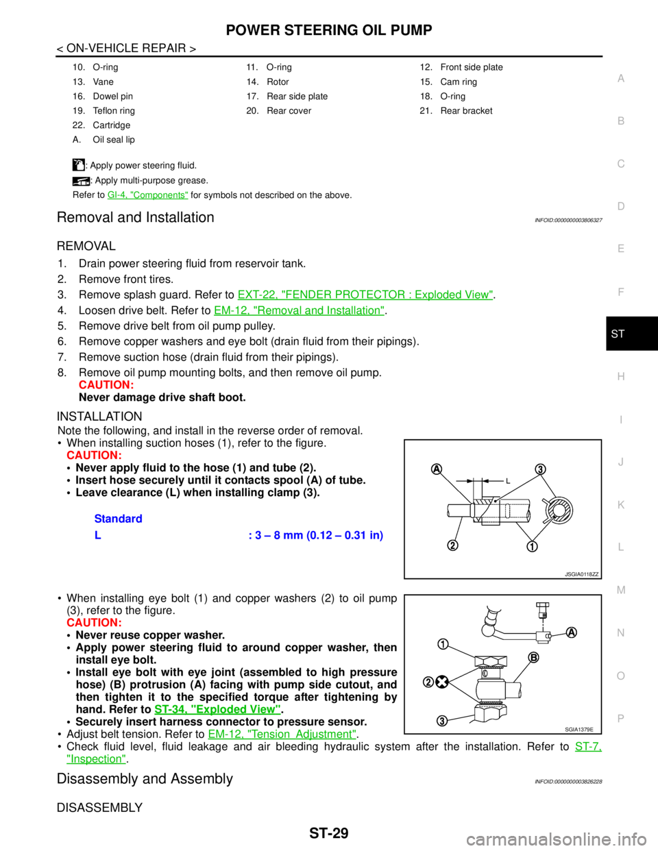
When installing suction hoses (1), refer to the figure.
CAUTION:
Never apply fluid to the hose (1) and tube (2).
Insert hose securely until it contacts spool (A) of tube.
Leave clearance (L) when installing clamp (3).
When installing eye bolt (1) and copper washers (2) to oil pump
(3), refer to the figure.
CAUTION:
Never reuse copper washer.
Apply power steering fluid to around copper washer, then
install eye bolt.
Install eye bolt with eye joint (assembled to high pressure
hose) (B) protrusion (A) facing with pump side cutout, and
then tighten it to the specified torque after tightening by
hand. Refer to ST-34, "
Exploded View".
Securely insert harness connector to pressure sensor.
Adjust belt tension. Refer to EM-12, "
TensionAdjustment".
Check fluid level, fluid leakage and air bleeding hydraulic system after the installation. Refer to ST-7,
"Inspection".
Disassembly and AssemblyINFOID:0000000003826228
DISASSEMBLY
10. O-ring 11. O-ring 12. Front side plate
13. Vane 14. Rotor 15. Cam ring
16. Dowel pin 17. Rear side plate 18. O-ring
19. Teflon ring 20. Rear cover 21. Rear bracket
22. Cartridge
A. Oil seal lip
: Apply power steering fluid.
: Apply multi-purpose grease.
Refer to GI-4, "
Components" for symbols not described on the above.
Standard
L : 3 – 8 mm (0.12 – 0.31 in)
JSGIA0118ZZ
SGIA1379E
Page 4420 of 5121

ST-30
< ON-VEHICLE REPAIR >
POWER STEERING OIL PUMP
1. Remove rear cover mounting bolts, and then remove rear cover from body assembly.
CAUTION:
Fix oil pump with a vise if necessary.
Use copper plates when fixing with a vise.
2. Remove O-ring from body assembly.
3. Remove rear side plate from cartridge, and then remove Teflon ring and O-ring from rear side plate.
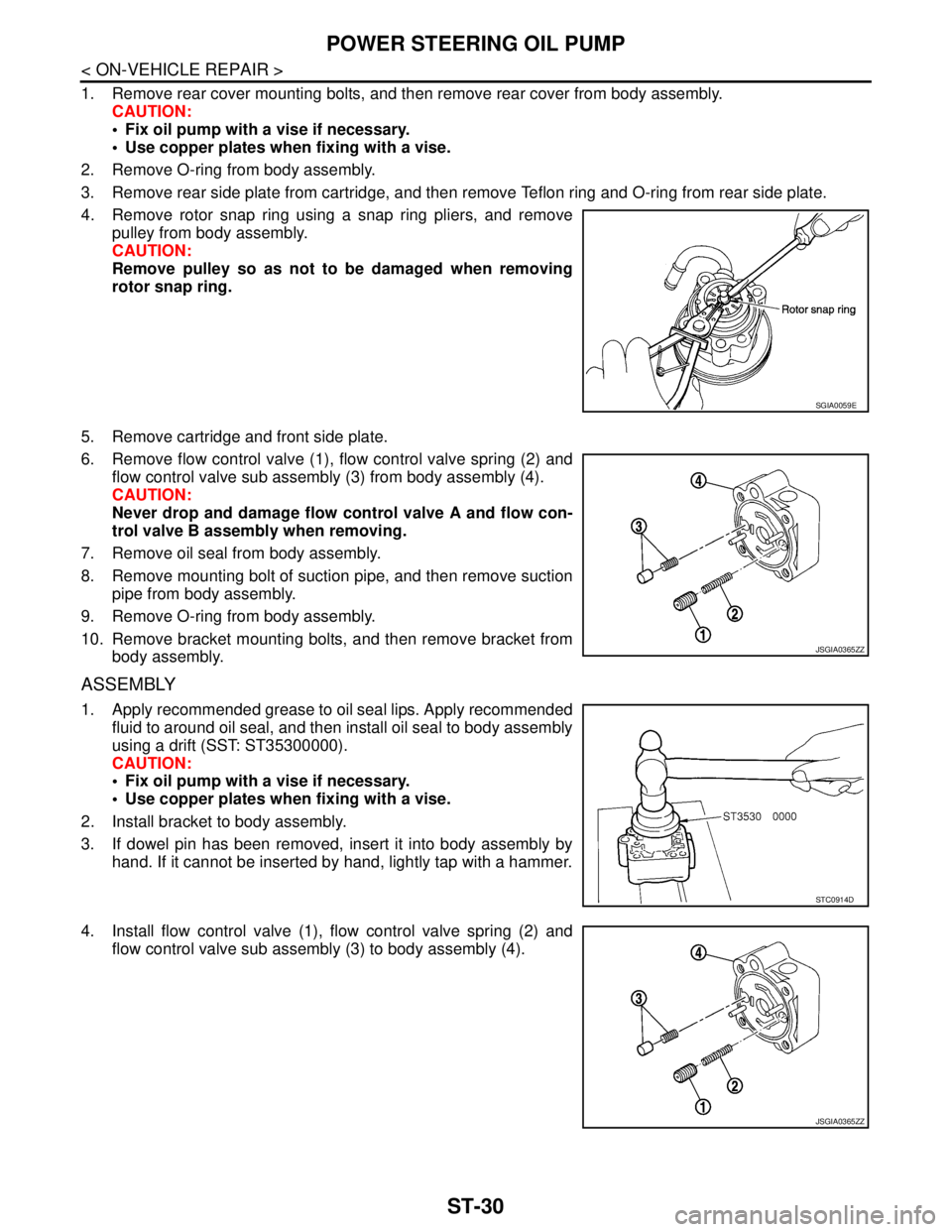
4. Remove rotor snap ring using a snap ring pliers, and remove
pulley from body assembly.
CAUTION:
Remove pulley so as not to be damaged when removing
rotor snap ring.
5. Remove cartridge and front side plate.
6. Remove flow control valve (1), flow control valve spring (2) and
flow control valve sub assembly (3) from body assembly (4).
CAUTION:
Never drop and damage flow control valve A and flow con-
trol valve B assembly when removing.
7. Remove oil seal from body assembly.
8. Remove mounting bolt of suction pipe, and then remove suction
pipe from body assembly.
9. Remove O-ring from body assembly.
10. Remove bracket mounting bolts, and then remove bracket from
body assembly.
ASSEMBLY
1. Apply recommended grease to oil seal lips. Apply recommended
fluid to around oil seal, and then install oil seal to body assembly
using a drift (SST: ST35300000).
CAUTION:
Fix oil pump with a vise if necessary.
Use copper plates when fixing with a vise.
2. Install bracket to body assembly.
3. If dowel pin has been removed, insert it into body assembly by
hand. If it cannot be inserted by hand, lightly tap with a hammer.
4. Install flow control valve (1), flow control valve spring (2) and
flow control valve sub assembly (3) to body assembly (4).
SGIA0059E
JSGIA0365ZZ
STC0914D
JSGIA0365ZZ
Page 4421 of 5121
POWER STEERING OIL PUMP
ST-31
< ON-VEHICLE REPAIR >
C
D
E
F
H
I
J
K
L
MA
B
ST
N
O
P
5. Install front side plate (3) with dowel pin (2) on flow control valve
(1) side as shown in the figure aligning with front side plate cut-
out (A) to body assembly (4).
6. Install cam ring as shown in the figure.
7. Install pulley to body assembly.
CAUTION:
Never damage oil seal when installing pulley.
8. Install rotor so that mark faces body assembly, and then install it
to pulley shaft.
9. Install vane to rotor so that arc of vane faces cam ring side.
10. Install rotor snap ring to slit of pulley shaft using a hammer and a
10 mm (0.39 in) box.
CAUTION:
Never damage rotor and pulley shaft.
Oil pump assembly must be replaced if rotor is damaged.
SGIA1189E
SGIA0612E
SGIA0989E
SGIA0613E
SGIA0063E