Page 4422 of 5121
ST-32
< ON-VEHICLE REPAIR >
POWER STEERING OIL PUMP
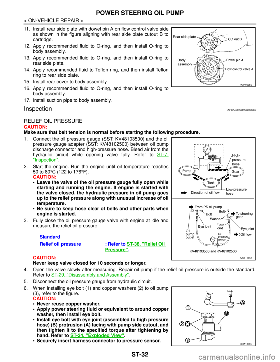
11. Install rear side plate with dowel pin A on flow control valve side
as shown in the figure aligning with rear side plate cutout B to
cartridge.
12. Apply recommended fluid to O-ring, and then install O-ring to
body assembly.
13. Apply recommended fluid to O-ring, and then install O-ring to
rear side plate.
14. Apply recommended fluid to Teflon ring, and then install Teflon
ring to rear side plate.
15. Install rear cover to body assembly.
16. Apply recommended fluid to O-ring, and then install O-ring to
body assembly.
17. Install suction pipe to body assembly.
InspectionINFOID:0000000003806329
RELIEF OIL PRESSURE
CAUTION:
Make sure that belt tension is normal before starting the following procedure.
1. Connect the oil pressure gauge (SST: KV48103500) and the oil
pressure gauge adapter (SST: KV48102500) between oil pump
discharge connector and high-pressure hose. Bleed air from the
hydraulic circuit while opening valve fully. Refer to ST-7,
"Inspection".
2. Start the engine. Run the engine until oil temperature reaches
50 to 80°C (122 to 176°F).
CAUTION:
Leave the valve of the oil pressure gauge fully open while
starting and running the engine. If engine is started with
the valve closed, the hydraulic pressure in oil pump goes
up to the relief pressure along with unusual increase of oil
temperature.
Be sure to keep hose clear of belts and other parts when
engine is started.
3. Fully close the oil pressure gauge valve with engine at idle and
measure the relief oil pressure.
CAUTION:
Never keep valve closed for 10 seconds or longer.
4. Open the valve slowly after measuring. Repair oil pump if the relief oil pressure is outside the standard.
Refer to ST-29, "
Disassembly and Assembly".
5. Disconnect the oil pressure gauge from hydraulic circuit.
6. When installing eye bolt (1) and copper washers (2) to oil pump
(3), refer to the figure.
CAUTION:
Never reuse copper washer.
Apply power steering fluid or equivalent to around copper
washer, then install eye bolt.
Install eye bolt with eye joint (assembled to high pressure
hose) (B) protrusion (A) facing with pump side cutout, and
then tighten it to the specified torque after tightening by
hand. Refer to ST-34, "
Exploded View".
Securely insert harness connector to pressure sensor.
PGIA0035E
Standard
Relief oil pressure : Refer to ST-38, "
Relief Oil
Pressure".
SGIA1225E
SGIA1379E
Page 4423 of 5121
POWER STEERING OIL PUMP
ST-33
< ON-VEHICLE REPAIR >
C
D
E
F
H
I
J
K
L
MA
B
ST
N
O
P
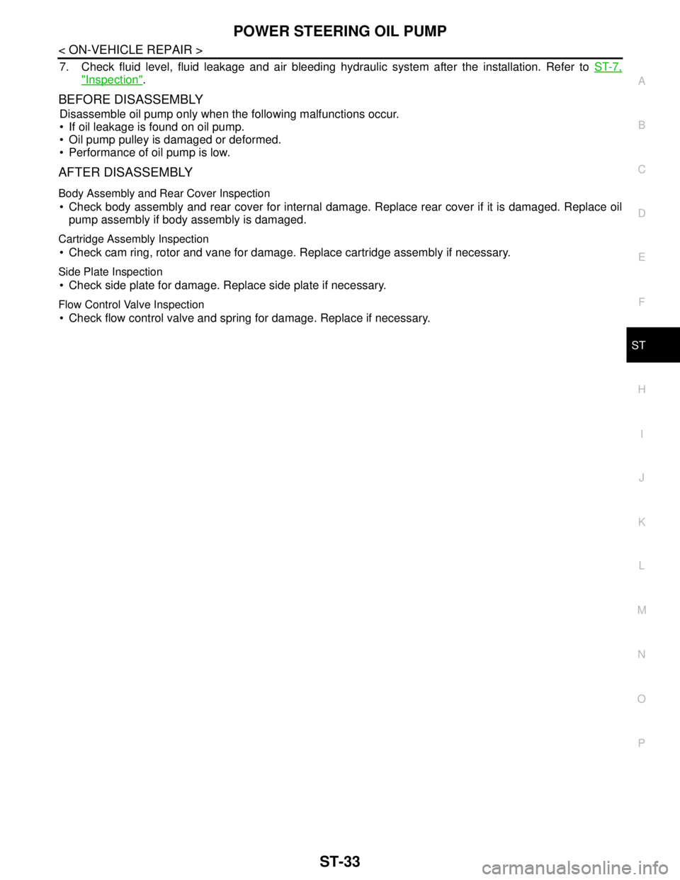
7. Check fluid level, fluid leakage and air bleeding hydraulic system after the installation. Refer to ST-7,
"Inspection".
BEFORE DISASSEMBLY
Disassemble oil pump only when the following malfunctions occur.
If oil leakage is found on oil pump.
Oil pump pulley is damaged or deformed.
Performance of oil pump is low.
AFTER DISASSEMBLY
Body Assembly and Rear Cover Inspection
Check body assembly and rear cover for internal damage. Replace rear cover if it is damaged. Replace oil
pump assembly if body assembly is damaged.
Cartridge Assembly Inspection
Check cam ring, rotor and vane for damage. Replace cartridge assembly if necessary.
Side Plate Inspection
Check side plate for damage. Replace side plate if necessary.
Flow Control Valve Inspection
Check flow control valve and spring for damage. Replace if necessary.
Page 4424 of 5121
ST-34
< ON-VEHICLE REPAIR >
HYDRAULIC LINE
HYDRAULIC LINE
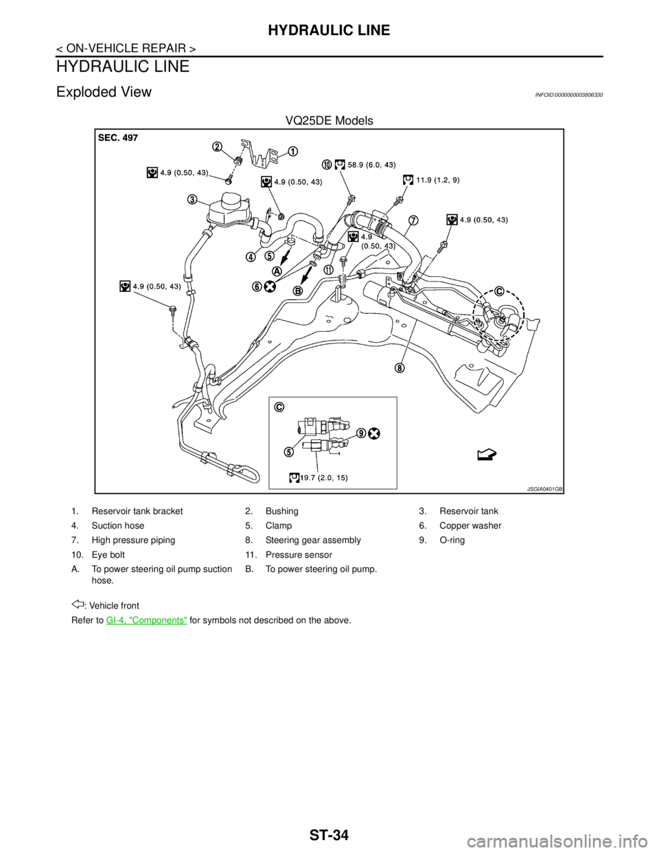
Exploded ViewINFOID:0000000003806330
VQ25DE Models
JSGIA0401GB
1. Reservoir tank bracket 2. Bushing 3. Reservoir tank
4. Suction hose 5. Clamp 6. Copper washer
7. High pressure piping 8. Steering gear assembly 9. O-ring
10. Eye bolt 11. Pressure sensor
A. To power steering oil pump suction
hose.B. To power steering oil pump.
: Vehicle front
Refer to GI-4, "
Components" for symbols not described on the above.
Page 4425 of 5121
HYDRAULIC LINE
ST-35
< ON-VEHICLE REPAIR >
C
D
E
F
H
I
J
K
L
MA
B
ST
N
O
P
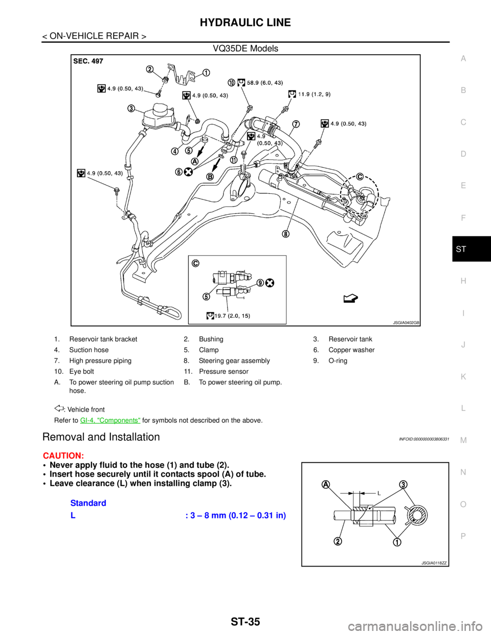
VQ35DE Models
Removal and InstallationINFOID:0000000003806331
CAUTION:
Never apply fluid to the hose (1) and tube (2).
Insert hose securely until it contacts spool (A) of tube.
Leave clearance (L) when installing clamp (3).
JSGIA0402GB
1. Reservoir tank bracket 2. Bushing 3. Reservoir tank
4. Suction hose 5. Clamp 6. Copper washer
7. High pressure piping 8. Steering gear assembly 9. O-ring
10. Eye bolt 11. Pressure sensor
A. To power steering oil pump suction
hose.B. To power steering oil pump.
: Vehicle front
Refer to GI-4, "
Components" for symbols not described on the above.
Standard
L : 3 – 8 mm (0.12 – 0.31 in)
JSGIA0118ZZ
Page 4429 of 5121
STC-1
STEERING
C
DE
F
H I
J
K L
M
SECTION STC
A
B
STC
N
O P
CONTENTS
STEERING CONTROL SYSTEM
BASIC INSPECTION ....... .............................2
DIAGNOSIS AND REPAIR WORK FLOW .... .....2
Work Flow ........................................................... ......2
FUNCTION DIAGNOSIS ...............................3
EPS SYSTEM ... .............................................. .....3
System Diagram .................................................. ......3
System Description ...................................................3
Component Parts Location ........................................5
Component Description .............................................5
COMPONENT DIAGNOSIS ..........................6
POWER SUPPLY AND GROUND CIRCUIT .. .....6
Description .......................................................... ......6
Diagnosis Procedure .................................................6
POWER STEERING SOLENOID VALVE ...........7
Description .......................................................... ......7
Diagnosis Procedure .................................................7
Component Inspection ..............................................8
ENGINE SPEED SIGNAL CIRCUIT ............... .....9
Description .......................................................... ......9
Diagnosis Procedure .................................................9
VEHICLE SPEED SIGNAL CIRCUIT .................11
Description .......................................................... ....11
Diagnosis Procedure ...............................................11
ECU DIAGNOSIS .........................................13
POWER STEERING CONTROL UNIT ..............13
Reference Value .................................................. ....13
Wiring Diagram - ELECTRONICALLY CON-
TROLLED POWER STEERING SYSTEM - ............
14
Fail-Safe .............................................................. ....15
SYMPTOM DIAGNOSIS ..............................17
UNBALANCE STEERING WHEEL TURNING
FORCE (TORQUE VARIATION) .......................
17
Description ........................................................... ....17
Diagnosis Procedure ...............................................17
PRECAUTION ..............................................18
PRECAUTIONS .................................................18
Precaution for Supplemental Restraint System
(SRS) "AIR BAG" and "SEAT BELT PRE-TEN-
SIONER" ............................................................. ....
18
Precaution Necessary for Steering Wheel Rota-
tion after Battery Disconnect ...................................
18
ON-VEHICLE REPAIR .................................19
POWER STEERING CONTROL UNIT ..............19
Exploded View ..................................................... ....19
Removal and Installation .........................................19
Page 4430 of 5121
STC-2
< BASIC INSPECTION >
DIAGNOSIS AND REPAIR WORK FLOW
BASIC INSPECTION
DIAGNOSIS AND REPAIR WORK FLOW
Work FlowINFOID:0000000003893521
DETAILED FLOW
1.COLLECT THE INFORMATION FROM THE CUSTOMER
It is also important to clarify customer complaints before inspection. First of all, reproduce symptoms and
understand them fully. Ask customer about his/her complaints carefully. In some cases, it is necessary to
check symptoms by driving vehicle with customer.
CAUTION:
Customers are not professional. It is dangerous to make an easy guess like “maybe the customer
means that...,” or “maybe the customer mentions this symptom”.
>> GO TO 2.
2.CHECK THE STATUS
1. Check the power steering fluid leakage and power steering fluid level. Refer to ST-7, "
Inspection".
2. Check the drive belt tension. Refer to EM-12, "
Checking".
3. Check the power steering gear for damages, cracks and fluid leakage. Refer to ST-26, "
Inspection".
4. Check the relief oil pressure. Refer to ST-32, "
Inspection".
>> GO TO 3.
3.DIAGNOSIS CHART BY SYMPTOM
Perform the diagnosis by symptom. Refer to STC-17, "
Diagnosis Procedure".
>> GO TO 4.
4.FINAL CHECK
Check the input/output standard values for the power steering control unit.
Are the power steering control unit input/output values within standard ranges respectively?
YES >> INSPECTION END
NO >> GO TO 2.
Page 4431 of 5121
EPS SYSTEM
STC-3
< FUNCTION DIAGNOSIS >
C
D
E
F
H
I
J
K
L
MA
B
STC
N
O
P
FUNCTION DIAGNOSIS
EPS SYSTEM
System DiagramINFOID:0000000003893522
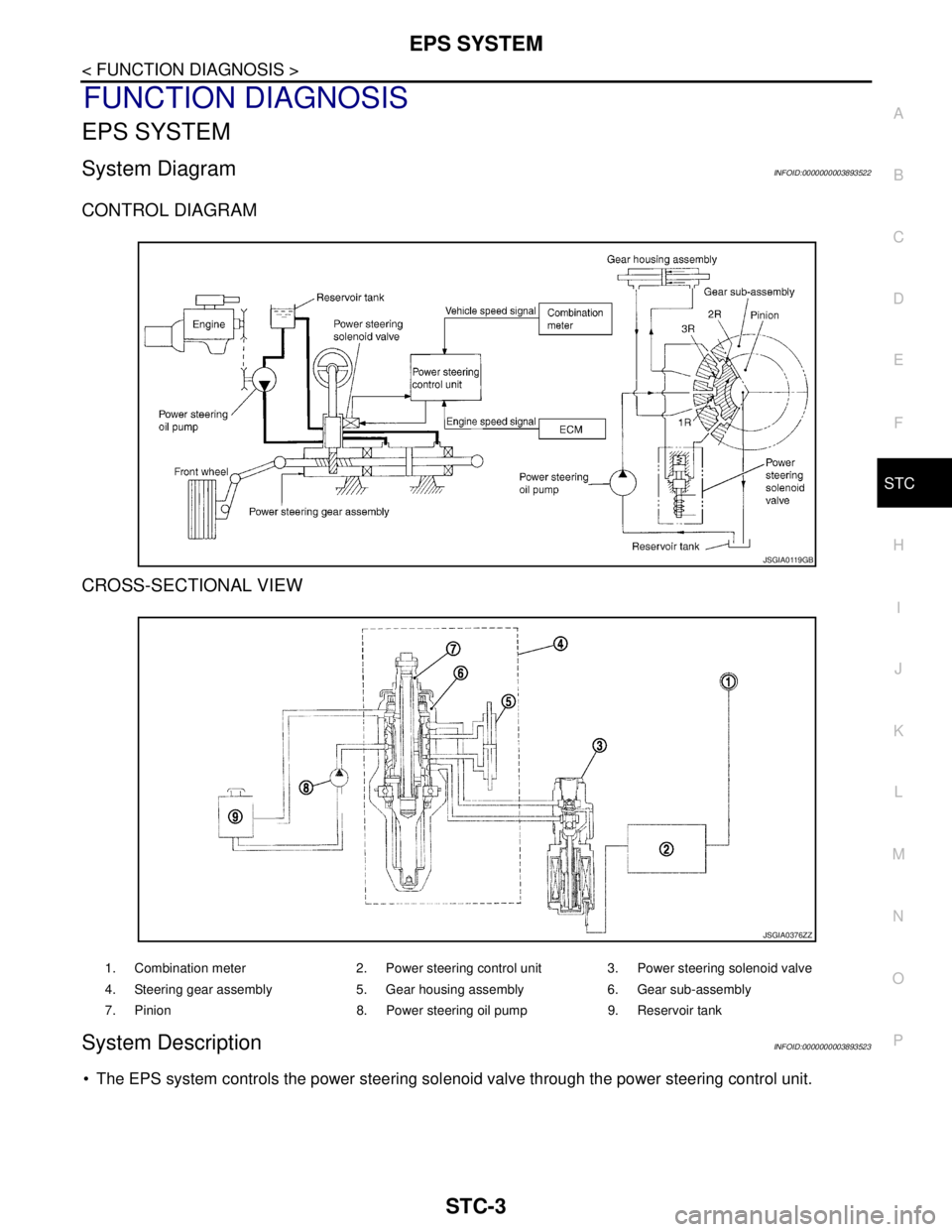
CONTROL DIAGRAM
CROSS-SECTIONAL VIEW
System DescriptionINFOID:0000000003893523
• The EPS system controls the power steering solenoid valve through the power steering control unit.
JSGIA0119GB
1. Combination meter 2. Power steering control unit 3. Power steering solenoid valve
4. Steering gear assembly 5. Gear housing assembly 6. Gear sub-assembly
7. Pinion 8. Power steering oil pump 9. Reservoir tank
JSGIA0376ZZ
Page 4432 of 5121
STC-4
< FUNCTION DIAGNOSIS >
EPS SYSTEM
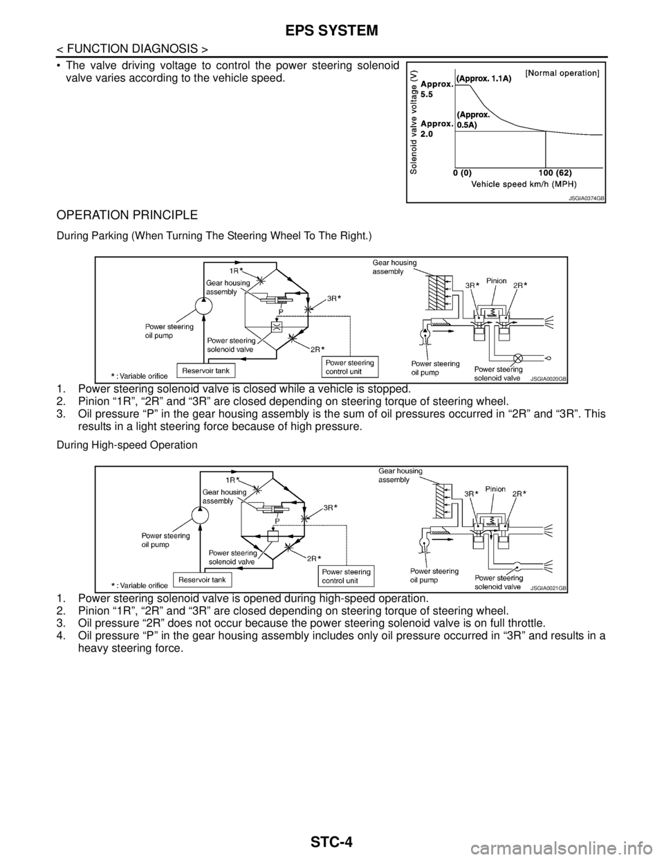
The valve driving voltage to control the power steering solenoid
valve varies according to the vehicle speed.
OPERATION PRINCIPLE
During Parking (When Turning The Steering Wheel To The Right.)
1. Power steering solenoid valve is closed while a vehicle is stopped.
2. Pinion “1R”, “2R” and “3R” are closed depending on steering torque of steering wheel.
3. Oil pressure “P” in the gear housing assembly is the sum of oil pressures occurred in “2R” and “3R”. This
results in a light steering force because of high pressure.
During High-speed Operation
1. Power steering solenoid valve is opened during high-speed operation.
2. Pinion “1R”, “2R” and “3R” are closed depending on steering torque of steering wheel.
3. Oil pressure “2R” does not occur because the power steering solenoid valve is on full throttle.
4. Oil pressure “P” in the gear housing assembly includes only oil pressure occurred in “3R” and results in a
heavy steering force.
JSGIA0374GB
JSGIA0020GB
JSGIA0021GB