2008 NISSAN TEANA engine oil
[x] Cancel search: engine oilPage 2490 of 5121
FSU-16
< REMOVAL AND INSTALLATION >
FRONT SUSPENSION MEMBER
REMOVAL AND INSTALLATION
FRONT SUSPENSION MEMBER
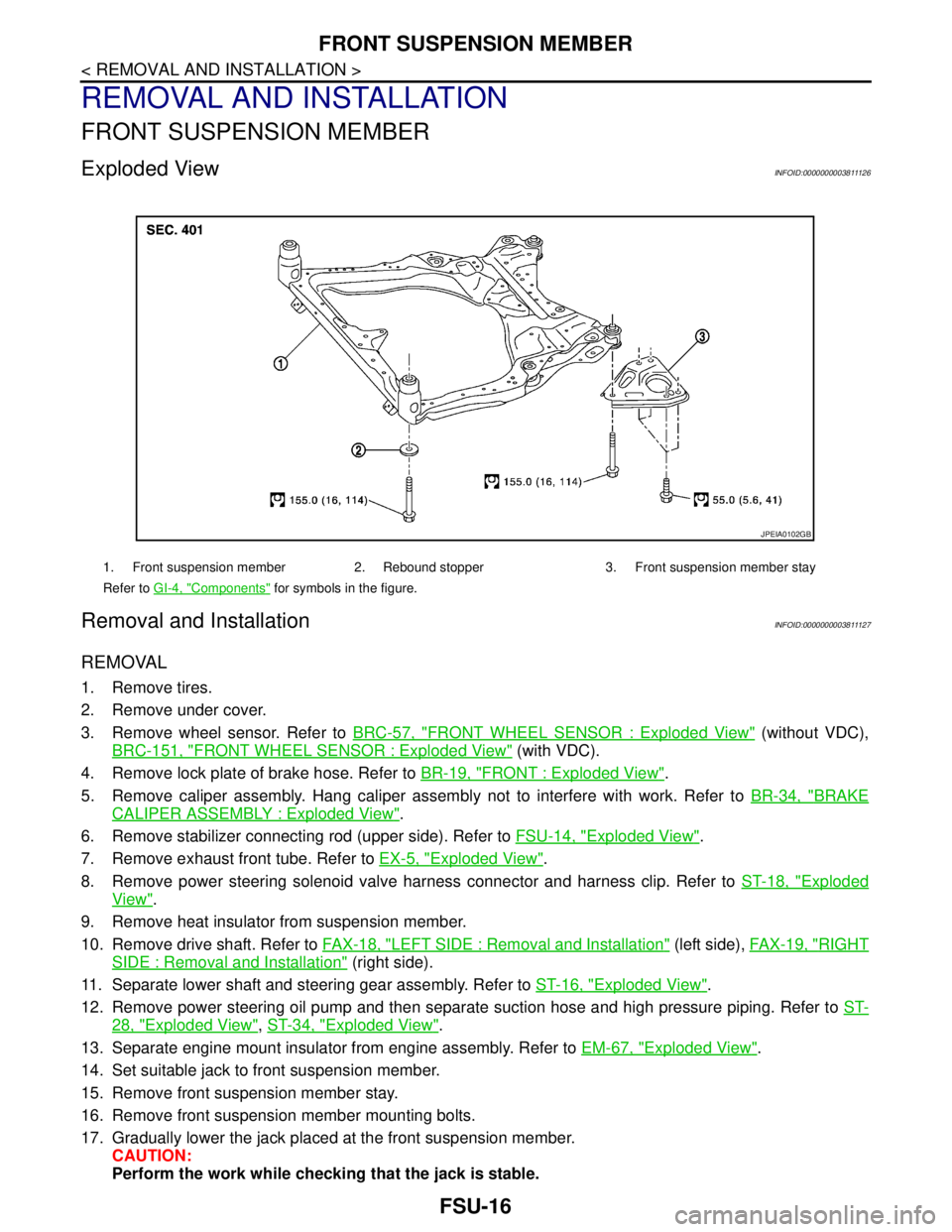
Exploded ViewINFOID:0000000003811126
Removal and InstallationINFOID:0000000003811127
REMOVAL
1. Remove tires.
2. Remove under cover.
3. Remove wheel sensor. Refer to BRC-57, "
FRONT WHEEL SENSOR : Exploded View" (without VDC),
BRC-151, "
FRONT WHEEL SENSOR : Exploded View" (with VDC).
4. Remove lock plate of brake hose. Refer to BR-19, "
FRONT : Exploded View".
5. Remove caliper assembly. Hang caliper assembly not to interfere with work. Refer to BR-34, "
BRAKE
CALIPER ASSEMBLY : Exploded View".
6. Remove stabilizer connecting rod (upper side). Refer to FSU-14, "
Exploded View".
7. Remove exhaust front tube. Refer to EX-5, "
Exploded View".
8. Remove power steering solenoid valve harness connector and harness clip. Refer to ST-18, "
Exploded
View".
9. Remove heat insulator from suspension member.
10. Remove drive shaft. Refer to FAX-18, "
LEFT SIDE : Removal and Installation" (left side), FAX-19, "RIGHT
SIDE : Removal and Installation" (right side).
11. Separate lower shaft and steering gear assembly. Refer to ST-16, "
Exploded View".
12. Remove power steering oil pump and then separate suction hose and high pressure piping. Refer to ST-
28, "Exploded View", ST-34, "Exploded View".
13. Separate engine mount insulator from engine assembly. Refer to EM-67, "
Exploded View".
14. Set suitable jack to front suspension member.
15. Remove front suspension member stay.
16. Remove front suspension member mounting bolts.
17. Gradually lower the jack placed at the front suspension member.
CAUTION:
Perform the work while checking that the jack is stable.
1. Front suspension member 2. Rebound stopper 3. Front suspension member stay
Refer to GI-4, "
Components" for symbols in the figure.
JPEIA0102GB
Page 2494 of 5121

GI-1
GENERAL INFORMATION
C
D
E
F
G
H
I
J
K
L
MB
GI
SECTION GI
N
O
P
CONTENTS
GENERAL INFORMATION
HOW TO USE THIS MANUAL ......................3
HOW TO USE THIS MANUAL ............................3
Description ................................................................3
Terms ........................................................................3
Units ..........................................................................3
Contents ....................................................................3
Relation between Illustrations and Descriptions .......4
Components ..............................................................4
HOW TO FOLLOW TROUBLE DIAGNOSES .....6
Description ................................................................6
How to Follow Test Groups in Trouble Diagnosis ......6
Key to Symbols Signifying Measurements or Pro-
cedures .....................................................................
7
HOW TO READ WIRING DIAGRAMS ................9
Connector Symbols ...................................................9
Sample/Wiring Diagram -Example- .........................10
Description ..............................................................11
ABBREVIATIONS ..............................................13
Abbreviation List ......................................................13
TIGHTENING TORQUE OF STANDARD
BOLTS ................................................................
14
Description ..............................................................14
Tightening Torque Table (New Standard Includ-
ed) ...........................................................................
14
TERMINOLOGY .................................................17
SAE J1930 Terminology List ...................................17
FEATURES OF NEW MODEL .....................21
IDENTIFICATION INFORMATION .....................21
Model Variation .......................................................21
Information About Identification or Model Code ......21
Dimensions .............................................................23
Wheels & Tires ........................................................23
PRECAUTION ..............................................24
PRECAUTIONS .................................................24
Description ...............................................................24
Precaution for Supplemental Restraint System
(SRS) "AIR BAG" and "SEAT BELT PRE-TEN-
SIONER" .................................................................
24
Precautions For Xenon Headlamp Service .............24
Precaution Necessary for Steering Wheel Rota-
tion after Battery Disconnect ...................................
24
Precaution for Procedure without Cowl Top Cover ....25
General Precautions ................................................25
Three Way Catalyst .................................................27
Multiport Fuel Injection System or Engine Control
System .....................................................................
27
Hoses ......................................................................27
Engine Oils ..............................................................28
Air Conditioning .......................................................28
Fuel ..........................................................................29
LIFTING POINT .................................................30
Commercial Service Tools .......................................30
Garage Jack and Safety Stand and 2-Pole Lift .......30
Board-On Lift ...........................................................31
TOW TRUCK TOWING .....................................32
Tow Truck Towing ...................................................32
Vehicle Recovery (Freeing a Stuck Vehicle) ...........32
BASIC INSPECTION ...................................34
SERVICE INFORMATION FOR ELECTRICAL
INCIDENT ..........................................................
34
Work Flow ................................................................34
Control Units and Electrical Parts ............................34
Intermittent Incident .................................................35
Circuit Inspection .....................................................37
CONSULT-III/GST CHECKING SYSTEM .........43
Description ...............................................................43
CONSULT-III Function and System Application*1 ....43
CONSULT-III/GST Data Link Connector (DLC)
Circuit ......................................................................
43
Page 2519 of 5121
GI-26
< PRECAUTION >
PRECAUTIONS
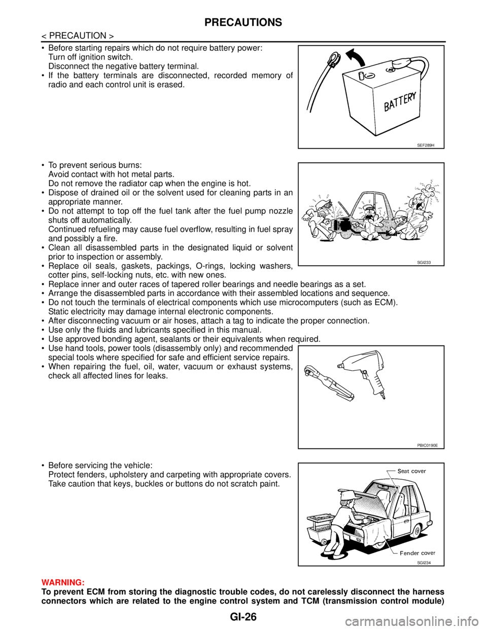
Before starting repairs which do not require battery power:
Turn off ignition switch.
Disconnect the negative battery terminal.
If the battery terminals are disconnected, recorded memory of
radio and each control unit is erased.
To prevent serious burns:
Avoid contact with hot metal parts.
Do not remove the radiator cap when the engine is hot.
Dispose of drained oil or the solvent used for cleaning parts in an
appropriate manner.
Do not attempt to top off the fuel tank after the fuel pump nozzle
shuts off automatically.
Continued refueling may cause fuel overflow, resulting in fuel spray
and possibly a fire.
Clean all disassembled parts in the designated liquid or solvent
prior to inspection or assembly.
Replace oil seals, gaskets, packings, O-rings, locking washers,
cotter pins, self-locking nuts, etc. with new ones.
Replace inner and outer races of tapered roller bearings and needle bearings as a set.
Arrange the disassembled parts in accordance with their assembled locations and sequence.
Do not touch the terminals of electrical components which use microcomputers (such as ECM).
Static electricity may damage internal electronic components.
After disconnecting vacuum or air hoses, attach a tag to indicate the proper connection.
Use only the fluids and lubricants specified in this manual.
Use approved bonding agent, sealants or their equivalents when required.
Use hand tools, power tools (disassembly only) and recommended
special tools where specified for safe and efficient service repairs.
When repairing the fuel, oil, water, vacuum or exhaust systems,
check all affected lines for leaks.
Before servicing the vehicle:
Protect fenders, upholstery and carpeting with appropriate covers.
Take caution that keys, buckles or buttons do not scratch paint.
WARNING:
To prevent ECM from storing the diagnostic trouble codes, do not carelessly disconnect the harness
connectors which are related to the engine control system and TCM (transmission control module)
SEF289H
SGI233
PBIC0190E
SGI234
Page 2521 of 5121
GI-28
< PRECAUTION >
PRECAUTIONS
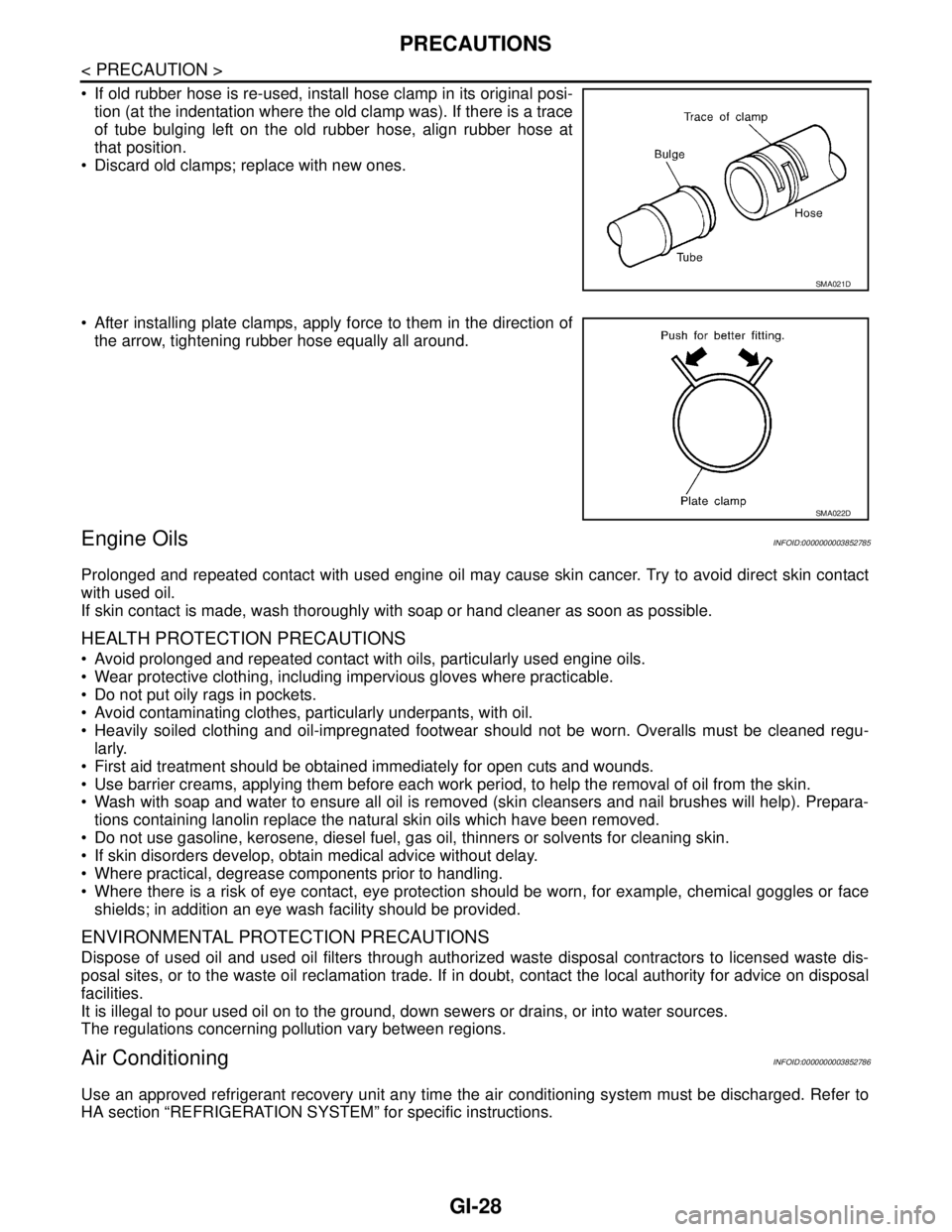
If old rubber hose is re-used, install hose clamp in its original posi-
tion (at the indentation where the old clamp was). If there is a trace
of tube bulging left on the old rubber hose, align rubber hose at
that position.
Discard old clamps; replace with new ones.
After installing plate clamps, apply force to them in the direction of
the arrow, tightening rubber hose equally all around.
Engine OilsINFOID:0000000003852785
Prolonged and repeated contact with used engine oil may cause skin cancer. Try to avoid direct skin contact
with used oil.
If skin contact is made, wash thoroughly with soap or hand cleaner as soon as possible.
HEALTH PROTECTION PRECAUTIONS
Avoid prolonged and repeated contact with oils, particularly used engine oils.
Wear protective clothing, including impervious gloves where practicable.
Do not put oily rags in pockets.
Avoid contaminating clothes, particularly underpants, with oil.
Heavily soiled clothing and oil-impregnated footwear should not be worn. Overalls must be cleaned regu-
larly.
First aid treatment should be obtained immediately for open cuts and wounds.
Use barrier creams, applying them before each work period, to help the removal of oil from the skin.
Wash with soap and water to ensure all oil is removed (skin cleansers and nail brushes will help). Prepara-
tions containing lanolin replace the natural skin oils which have been removed.
Do not use gasoline, kerosene, diesel fuel, gas oil, thinners or solvents for cleaning skin.
If skin disorders develop, obtain medical advice without delay.
Where practical, degrease components prior to handling.
Where there is a risk of eye contact, eye protection should be worn, for example, chemical goggles or face
shields; in addition an eye wash facility should be provided.
ENVIRONMENTAL PROTECTION PRECAUTIONS
Dispose of used oil and used oil filters through authorized waste disposal contractors to licensed waste dis-
posal sites, or to the waste oil reclamation trade. If in doubt, contact the local authority for advice on disposal
facilities.
It is illegal to pour used oil on to the ground, down sewers or drains, or into water sources.
The regulations concerning pollution vary between regions.
Air ConditioningINFOID:0000000003852786
Use an approved refrigerant recovery unit any time the air conditioning system must be discharged. Refer to
HA section “REFRIGERATION SYSTEM” for specific instructions.
SMA021D
SMA022D
Page 2523 of 5121
GI-30
< PRECAUTION >
LIFTING POINT
LIFTING POINT
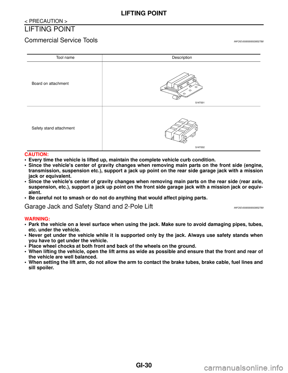
Commercial Service ToolsINFOID:0000000003852788
CAUTION:
Every time the vehicle is lifted up, maintain the complete vehicle curb condition.
Since the vehicle's center of gravity changes when removing main parts on the front side (engine,
transmission, suspension etc.), support a jack up point on the rear side garage jack with a mission
jack or equivalent.
Since the vehicle's center of gravity changes when removing main parts on the rear side (rear axle,
suspension, etc.), support a jack up point on the front side garage jack with a mission jack or equiv-
alent.
Be careful not to smash or do not do anything that would affect piping parts.
Garage Jack and Safety Stand and 2-Pole LiftINFOID:0000000003852789
WARNING:
Park the vehicle on a level surface when using the jack. Make sure to avoid damaging pipes, tubes,
etc. under the vehicle.
Never get under the vehicle while it is supported only by the jack. Always use safety stands when
you have to get under the vehicle.
Place wheel chocks at both front and back of the wheels on the ground.
When lifting the vehicle, open the lift arms as wide as possible and ensure that the front and rear of
the vehicle are well balanced.
When setting the lift arm, do not allow the arm to contact the brake tubes, brake cable, fuel lines and
sill spoiler.
Tool name Description
Board on attachment
Safety stand attachment
S-NT001
S-NT002
Page 2528 of 5121
SERVICE INFORMATION FOR ELECTRICAL INCIDENT
GI-35
< BASIC INSPECTION >
C
D
E
F
G
H
I
J
K
L
MB
GI
N
O
P
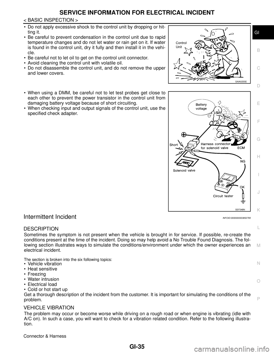
Do not apply excessive shock to the control unit by dropping or hit-
ting it.
Be careful to prevent condensation in the control unit due to rapid
temperature changes and do not let water or rain get on it. If water
is found in the control unit, dry it fully and then install it in the vehi-
cle.
Be careful not to let oil to get on the control unit connector.
Avoid cleaning the control unit with volatile oil.
Do not disassemble the control unit, and do not remove the upper
and lower covers.
When using a DMM, be careful not to let test probes get close to
each other to prevent the power transistor in the control unit from
damaging battery voltage because of short circuiting.
When checking input and output signals of the control unit, use the
specified check adapter.
Intermittent IncidentINFOID:0000000003852795
DESCRIPTION
Sometimes the symptom is not present when the vehicle is brought in for service. If possible, re-create the
conditions present at the time of the incident. Doing so may help avoid a No Trouble Found Diagnosis. The fol-
lowing section illustrates ways to simulate the conditions/environment under which the owner experiences an
electrical incident.
The section is broken into the six following topics: Vehicle vibration
Heat sensitive
Freezing
Water intrusion
Electrical load
Cold or hot start up
Get a thorough description of the incident from the customer. It is important for simulating the conditions of the
problem.
VEHICLE VIBRATION
The problem may occur or become worse while driving on a rough road or when engine is vibrating (idle with
A/C on). In such a case, you will want to check for a vibration related condition. Refer to the following illustra-
tion.
Connector & Harness
SAIA0255E
SEF348N
Page 2543 of 5121
GI-50
< BASIC INSPECTION >
INSPECTION AND ADJUSTMENT
*: Not equippedPower window
controlPower window control systemPWC-5, "
ADDITIONAL SERVICE WHEN
REMOVING BATTERY NEGATIVE TERMI-
NAL : Description"
Sunroof system Sunroof system* —
Sunshade system Sunshade system* —
Rear view monitorRear view monitor
possible route line
center position ad-
justmentDISPLAY AND AUDIO SYSTEMAV- 4 7 , "
ADDITIONAL SERVICE WHEN
REMOVING BATTERY NEGATIVE TERMI-
NAL : Description"
BOSE AUDIO WITHOUT NAVIGATIONAV- 1 8 7 , "
ADDITIONAL SERVICE WHEN
REMOVING BATTERY NEGATIVE TERMI-
NAL : Description"
BOSE AUDIO WITH NAVIGATIONAV- 4 0 0 , "
ADDITIONAL SERVICE WHEN
REMOVING BATTERY NEGATIVE TERMI-
NAL : Description"
Around view moni-
torPredicted conurse line center position adjustment* —
Automatic back
door systemAutomatic back door system* —
Engine oil level
readEngine oil level read* — SYSTEM ITEM REFERENCE
Page 2594 of 5121
REFRIGERANT
HA-25
< ON-VEHICLE MAINTENANCE >
C
D
E
F
G
H
J
K
L
MA
B
HA
N
O
P
WARNING:
Never breath A/C refrigerant and lubricant vapor or mist. Exposure may irritate eyes, nose and throat.
Use only approved recovery/recycling recharging equipment to discharge HFC-134a (R-134a) refriger-
ant. Ventilate work area before resuming service if accidental system discharge occurs. Additional
health and safety information may be obtained from refrigerant and lubricant manufacturers.
1.CHECK A/C SYSTEM
1. Check that A/C system operates normally. Refer to the following.
-HAC-8, "
Description & Inspection" (WITHOUT 7 INCH DISPLAY)
-HAC-108, "
WITHOUT INTELLIGENT AIR CONDITIONER SYSTEM : Description & Inspection" [WITH 7
INCH DISPLAY (WITHOUT INTELLIGENT AIR CONDITIONER SYSTEM)]
-HAC-112, "
WITH INTELLIGENT AIR CONDITIONER SYSTEM : Description & Inspection" [WITH 7 INCH
DISPLAY (WITH INTELLIGENT AIR CONDITIONER SYSTEM)]
2. Check if there is a large amount of leakage of refrigerant or oil.
CAUTION:
Never perform the lubricant return operation if a large amount of leakage of lubricant is detected.
Is the inspection result normal?
YES >> GO TO 2.
NO >> Check for refrigerant leakage. Refer to HA-32, "
Inspection".
2.LUBRICANT RETURN OPERATION
1. Start the engine and run it as follows.
- Engine speed: Idle - 1,200 rpm
- A/C switch: ON
- Blower speed: Max. position
- Air inlet: Recirculation (REC)
- Set temperature: FULL HOT
2. Perform lubricant return operation for approximately 10 minutes.
3. Stop the engine.
>> GO TO 3.
3.CHECK RECOVERY/RECYCLING RECHARGING EQUIPMENT
1. Operate recovery/recycling recharging equipment.
CAUTION:
Follow the instructions of the manufacturer for the handling or maintenance of the equipment.
Never fill the equipment with undesignated refrigerant.
2. Check the gauge pressure of recovery/recycling recharging equipment.
Is there pressure?
YES >> GO TO 4.
NO >> GO TO 5.
4.DISCHARGE REFRIGERANT INSIDE PIPES
Discharge the refrigerant from the high-pressure hose and low-pressure hose of recovery/recycling recharging
equipment.
>> GO TO 5.
5.CONNECT RECOVERY/RECYCLING RECHARGING EQUIPMENT
1. Remove the service valve caps from the vehicle.
2. Connect recovery/recycling recharging equipment to the service valves.
>> GO TO 6.
6.DISCHARGE REFRIGERANT FROM THE VEHICLE
Operate recovery/recycling recharging equipment to discharge the refrigerant from the vehicle.